I-880 / USER GUIDE 5
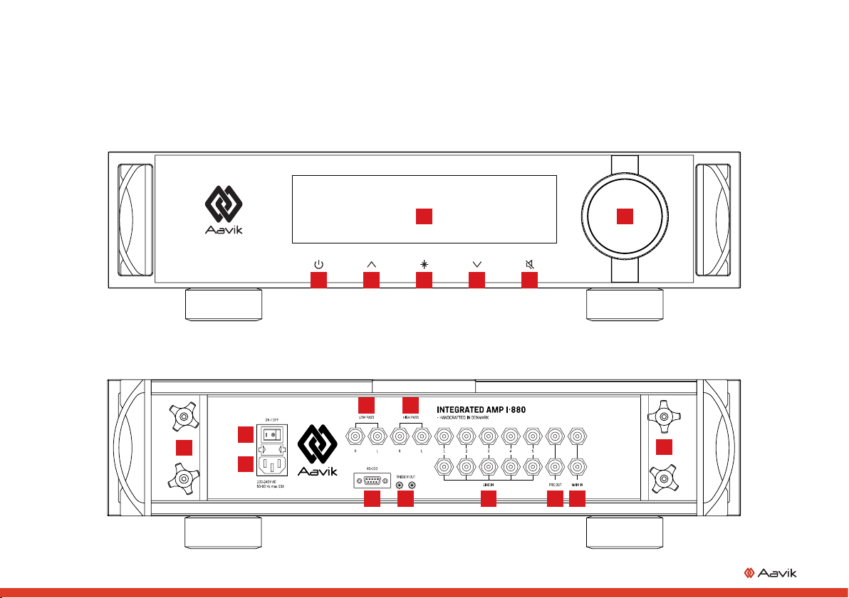
FRONT PANEL FUNCTIONS
1DISPLAY
During normal operation the left side of the display
shows the selected source, and the right side shows
the volume setting.
It is possible to change the source with the up/down but-
tons. When changing settings (see “MENU FUNCTIONS”
page 8), the display will show the setting being changed.
In the event of an error, a line at the bottom of the
display will show error messages. The possible errors
are DC, over current and high temperature. The errors
are explained in the following section.
OVER CURRENT
If the amp displays “Error: Short Right” or “Error: Short
Left”, too much current is running through the output
stage. This usually occurs because of a short circuit
in the speaker wiring. When the error is detected, the
speaker output(s) will be switched off, and you have
to switch the amplifier off and back on, to re-enable
normal operation. Before you switch the amp back
on, make sure that there are no wiring errors. The
error could be strands of wire from the speaker cable
touching each other or the metalwork of the amplifier.
If the error is displayed again after power cycling the
amplifier, and even with speakers disconnected, the
amplifier has been damaged, and will need servicing.
DC
If the amp displays “Error: DC Right” or “Error: DC Left”,
DC is present on the output(s) of the amplifier. When
this occurs, the speaker output(s) are disabled to
protect the speakers. If music is playing, the sound
will be distorted and low in level. The DC could come
from the preamp or a signal source. Try switching
the amplifier off and back on. If the DC error is still
present, try switching the amplifier off, disconnect
the input cable(s), and switch the amp back on. If the
DC error persists, with input cables disconnected, the
error is in the power amplifier. Otherwise the error is in
the preamplifier or the signal source.
HIGH TEMPERATURE
If the amp displays “Error: Temp High”, the tempera-
ture inside the amplifier is reaching critical levels. This
can occur if the ambient temperature is too high and/
or the amplifier has been delivering large amounts of
power into low impedance speakers. When the error
is first shown, it is only a warning. If the temperature
drops again, the message will clear. If the temperature
continues to rise however, the amplifier will switch
off. In that case, you have to let the amplifier cool off
for some time, and then switch it off and on using the
main power switch on the back panel.
2STANDBY
Press the standby button to place the amplifier in
standby mode, or to switch on the amplifier from
standby mode. When the amplifier is in standby mode,
the only light showing on the amplifier will be a dim
LED illuminating the standby button. When you switch
on the amplifier, the outputs will be muted, and a line
will illuminate at the bottom of the displays, starting
in the lower left corner.
During the start-up cycle, the circuits of the amp will
stabilize, and any power amp(s) connected to the pre
outs will have some time to stabilize. When using trig-
ger cables between the amplifier and power amp(s),
the power amp(s) will be switched on and off together
with the amplifier.
3UP BUTTON
The up button is used for switching inputs, and for
changing menu options, when in the menu. See ”MENU
FUNCTIONS” page 8.
4MENU BUTTON
The menu button is used for accessing the menu. See
”MENU FUNCTIONS” page 8.
5DOWN BUTTON
The down button is used for switching inputs, and for
changing menu options, when in the menu. See ”MENU
FUNCTIONS” page 8.
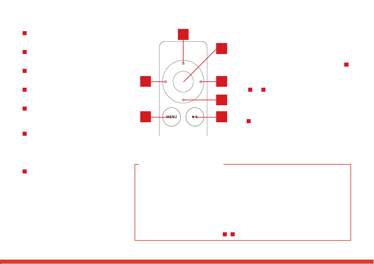
6MUTE / REMOTE CONTROL
PAIRING BUTTON
The mute button has multiple functions. When you
press this button briefly, it will mute the speaker
outputs of the amplifier, and also the pre outs with the
standard configuration (see “MENU FUNCTIONS” page
8). The display will show ”Mute” instead of the volume
setting.
For remote pairing instructions, see page 7.
7VOLUME CONTROL
(ROTATING KNOB)
Use the rotating knob to change the volume or menu
settings.