ACRS ELECTRONIC 3 Technical specifications

INSTRUCTION
MANUAL
FOR
DISHWASHING
MACHINES
MOD.
ACRS
ELECTRONIC 3

instruction for the user
2

instruction for the user
3
INDEX
Introduction...........................................................................................................................................4
INSTRUCTIONS FOR USE.................................................................................................................6
Notes before washing..........................................................................................................................8
Operation and use............................................................................................................................. 8
Datashowing 10
Washing.............................................................................................................................................11
Instruction during the washing...........................................................................................................11
Instruction after the washing..............................................................................................................12
Useful advice......................................................................................................................................13
Maintenance.......................................................................................................................................13
Hygienic care......................................................................................................................................13
Removal of encrustations..................................................................................................................13
Optimum results ................................................................................................................................13
Prolonged standstill of the machine...................................................................................................14
Self cleaning (optional).......................................................................................................................14
Safety device.................................................................................................................................... 15
Micro limit switch SS1........................................................................................................................15
Doors micro switches SS2-SS2A...SS20A.......................................................................................15
Emergency stop push-button S3-S3A...............................................................................................15
Slip clutch...........................................................................................................................................15
Motor protection..................................................................................................................................16
Resistances protection......................................................................................................................16
Other risks..........................................................................................................................................16
Risk of squeezing the upper limbs.....................................................................................................16
Risks of burning the upper limbs .......................................................................................................16
INSTRUCTION FOR INSTALLATION AND MAINTENANCE.............................................................17
location...............................................................................................................................................18
installation and connections...............................................................................................................18
Electrical connection..........................................................................................................................19
Hot water connection (B)...................................................................................................................19
Cold water connection (D) (only for machines with prewash, steam condenser and/or heat recovery
unit).....................................................................................................................................................20
Steam connection (E) (only for steam heated machines).................................................................20
Water drain (A)...................................................................................................................................20
Steam discharge (F) (only for steam heated machines)...................................................................20
Steam elimination...............................................................................................................................20
Before starting the machine...............................................................................................................21
Data setting 22
Torque limiter.....................................................................................................................................23
Loading and unloading of the machine..............................................................................................23
Machine dismantling...........................................................................................................................23
A few inconveniences which might occur during the use of the dishwasher, their reasons and
remedies ............................................................................................................................................24
TECHNICAL MENU

instruction for the user
4
INTRODUCTION
1) Please read carefully the remarks contained in this booklet, as they supply important indications as to the
security of installation, use and maintenance. Keep it for further consultation by the staff.
2) After having removed the packing, control the integrity of the machine. In case of any doubt, don't use it
and revert to the qualified staff. The packing elements (plastic bags, expanded polystyrene, nails etc.) must
not be left within reach of children, as they might represent potential danger sources.
3) Before connecting the machine, control if the data on the plate correspond to those of the electric and
hydraulic distribution net.
4) The installation has to be effected by qualified staff according to the indications of the manufacturer.
5) This machine must only be used for the purpose designed: washing of dishes such as plates, glasses,
cups, cutlery, trays etc. Any other use such as washing of machine parts or objects with higher dimensions
than the working passage of which the machine allows is improper and therefore dangerous.
6) The machine must be used only by trained staff.
7) The staff handling the objects after the washing cycles has to respect strictly the hygienic rules in force.
8) Do not keep the machine in places with temperatures under 0°C.
9) The protection degree of the machine is IPX4 and it must therefore not be washed with direct water jets
at high pressure.
10) After having taken off the tension, only qualified staff is allowed to accede to the control panel.
11) The machine is built according to I.E.C.-standard 89/336 relating to the elimination of radio
interferences and to the electromagnetic compatibility.
12) In conformity with I.E.C.-standard our dishwashers are manufactured according to the standard of
excellent technical level valid in Italy and abroad.
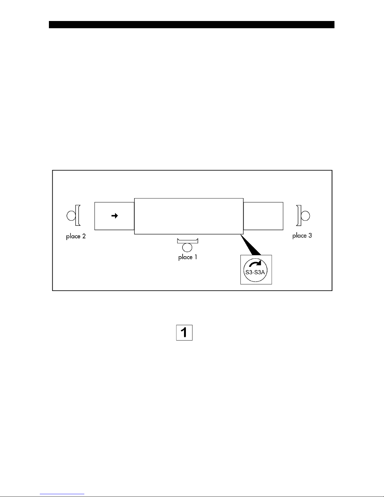
13) Noise of empty machine operation, measured at the working places (fig. 1) at 1.6 m height, is as
follows:
place 1 place 2 place 3
LeqA
level equivalent to
the acoustic pressure
dB(A)
The peak of the acoustic pressure level is not indicated, as far below 130dB(C):
instruction for the user
5

instruction for the user
6
INSTRUCTIONS FOR USE
instruction for the user
7

instruction for the user
8
NOTES BEFORE WASHING
1) Make sure that:
??wall switch is connected
??water and steam taps* are open
??there is no lack of water and steam* in the net
??tank and pump suction filters are in their seat
??overflow pipes are closed
??curtains are correctly placed
??inspection doors are closed
??detergent and rinse aid dispensers are full
??dimensions of the dishware do not exceed those prescribed
(*) this applies only to machines with steam heating
OPERATION AND USE
SWITCHING ON
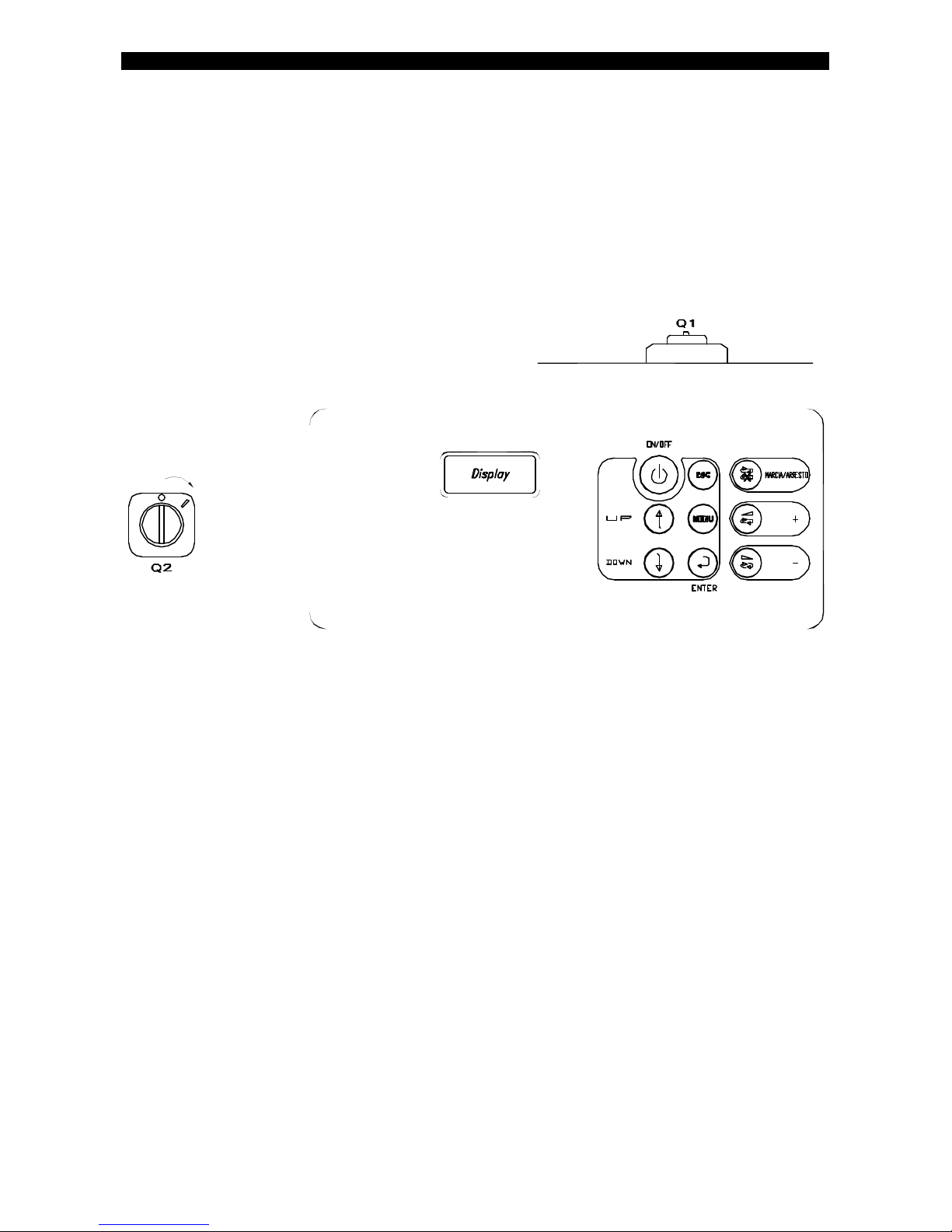
1. Rotate the main switch "Q1" and the switch "Q2" to the position "I";
the display shows:
“POWER ON ".
“PUSH ON/OFF BUTTON TO SWITCH THE MACHINE ON”.
2. Push ON/OFF button;
the display shows:
“MACHINE ON”
“PRE-FILL RINSE TANK”
“TANK EMPTY”
Each time machine is turned on an automatic rinse cycle takes place with a duration of 2
minutes, making sure that the rinse water booster does not run empty.
3. After 2 min. ;
the display shows:
“MACHINE ON”
“TANK FILL”
“TANK EMPTY”
4. Following ;
the display shows:
“MACHINE ON”
“HEATING”.

instruction for the user
9
WASHING
1. The display shows:
“MACHINE READY”.
“PUSH START TO START THE WASHING”.
“DRIVE SYSTEM NOT STARTED, X SPEED” .
2. Push START/STOP to start the washing;
the display shows:
“WASHING”.
“STOP THE WASHING BY PUSHING STOP”
“DRIVE SYSTEM RUNNING, X SPEED.
STOP THE WASHING
1. Stop the washing by pushing START/STOP ;
the display shows:
“MACHINE READY”.
“PUSH START TO START THE WASHING”.
“DRIVE SYSTEM NOT STARTED, X SPEED”
SPEED CHANGE
1. Push "-" button to select 1° speed
2. Push "+" button to select 2° speed.
The display shows:
“WASHING”.
“STOP THE WASHING BY PUSHING STOP”
“DRIVE SYSTEM RUNNING, X SPEED.

instruction for the user
10
ALARMS
The display indicates various malfunctions:
"AUTOTIMER ON" after the set Autotimer period the pumps stop but the conveyor continues
to run to permit the loading of other dishes.
"LIMIT SWITCH ON", the conveyor stops when the limit switch on the outlet is activated. The
conveyor starts automatically when dishes are removed from the outlet.
"DOORS OPEN". The machine stops automatically when the doors are opened.
"EMERGENCY PUSH BUTTON ACTIVATED".
“BOOSTER SAFETY THERMOSTAT ACTIVATED”
“TANK EMPTY”
“DRIVE MOTOR HAS JAMMED”
“TERMAL-SWITCH ON”
“LOW WATER INLET TEMPERATURE”
“LOW RINSE WATER TEMPERATURE”
“DRYER SAFETY THERMOSTAT ACTIVATED”
“WATER INLET QUANTITY NOT SUFFICIENT”
DATASHOWING
The display shows:
“MACHINE READY”.
“PUSH START TO START THE WASHING”.
“DRIVE SYSTEM NOT STARTED, X SPEED”
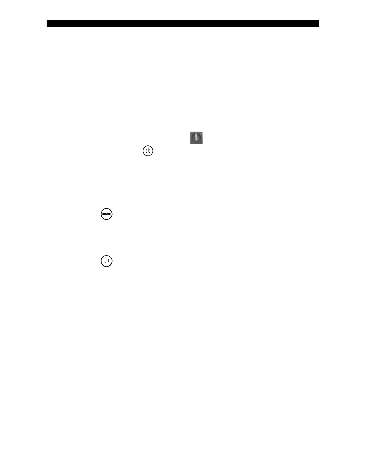
1. Push twice MENU button.
2. push ENTER button.
3. Push UP/DOWN buttons (Every pressing calls the following texts one after the
other on the display ):
“AUTOTIMER xxxsec."
“RINSE PROLONGATION xxxsec.”
“HYDRAULIC SUPPLY T=xx°C,
“SECTOR 1,............SECTOR 8, T=x°C, T SETPOINT T=x°C”
“STEAM COMSUMPTION”
"ENERGY CONSUMPTION"
"TOTALS WASHING TIME H xxxxx"
"MAINTENANCE AFTER H xxxxx"
4. Push ESC button.
5. Push ENTER button.

instruction for the user
11
WASHING
1. Before starting the wash operations remove from the dishes possible leftovers and grease.
2. Effect a preliminary softening of cutlery and also of dishes if they are washed after some
time from their use.
3. Put the dishware in the baskets.
4. Make sure that the plates are turned towards the exit of the machine.
5. If the person attending to this work is unable to remove the rack from the exit table, a limit
switch ensures the stop of the transport and rinsing operation. Work is resumed by simply
removing the rack from the limit switch.
INSTRUCTION DURING THE WASHING
1) Do not put your bare hands in the hot and detergent water of the tanks, as this might cause
burns and skin irritations. Should this happen rinse your hands immediately under fresh
water.
2) When the machine is functioning do not open inspection doors quickly.
3) Use only specific antifoam detergents for industrial dishwashers, supplied by well-known
and reputable companies.
4) Disconnect the machine in case of breakdown or defective functioning. For possible repair
work rely exclusively on a Technical Assistance, approved by the manufacturer and request
that original spare parts be used.
5) At periodic intervals stop the machine, remove tank filters and remove the residues which
have accumulated. Do not extract the suction pump filters when the tank is full.
6) If the transport system is stopped by means of the safety device (slip clutch), stop the
machine by pressing the mushroom-shaped emergency push-button S3-S3A before
removing the obstacle which caused the trouble.
7) Keep under control detergent and rinse aid level in the respective dispensers.
8) Make sure that water temperatures maintain their established values: prewash 35/45°C,
main wash 50/60°C, rinse 75/85°C.
The non-observance of the above mentioned points may compromise the safety of the machine
and the staff.
instruction for the user
12
INSTRUCTION AFTER THE WASHING
When the wash operations are completed:
1. Press ON/OFF button and turn switch “Q2” into position “O” to switch off the
machine.
2. Disconnect the machine by means of the main switch “Q1” and close the tap for
water and steam supply (this applies only to steam heating machines).
3. Lift the inspection doors and make sure that they are perfectly hooked to the support.
4. Lift and turn the overflow pipes in order to empty the tanks.
5. Take off the curtains and the filters for cleaning.
6. Control and, if necessary, clean the wash and rinse nozzles by removing them from their
respective columns. Wash the tanks accurately with jets of water.
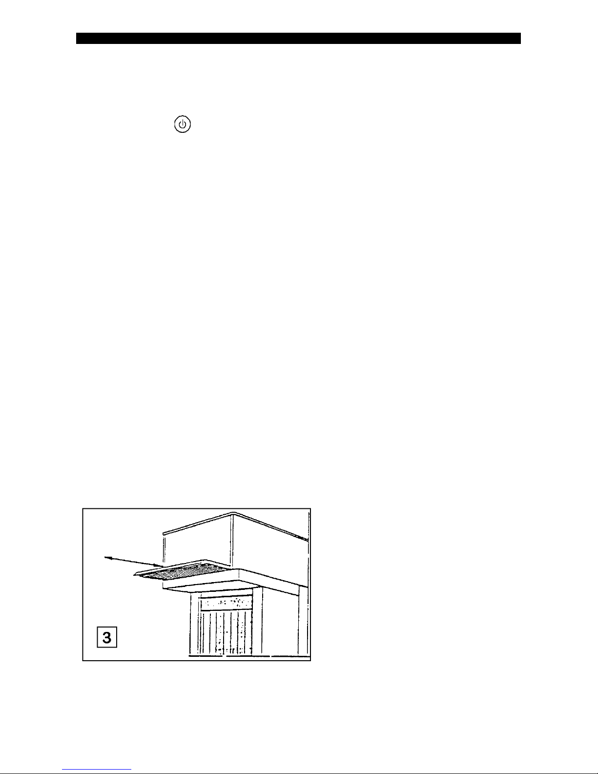
7. For machines with steam condenser remove steam suction filter for cleaning (fig. 3):
8. Clean the external surface of the machine with a damp cloth; don't use jets of water, as,
apart from being dangerous, they might damage the electric parts; don't use abrasive
detergents or those containing chlorine.
9. Reassemble all devices into their locations, taking care that:
??the curtains are turned with their short side towards the entry of the dishware
??the nozzles are turned towards the dishware
10.Keep doors open in order to avoid unpleasant odours.

instruction for the user
13
USEFUL ADVICE
Maintenance
IMPORTANT: Before effecting cleaning and maintenance work, disconnect the machine from
the electric supply net by switching off the wall switch or the disconnecting main switch "Q1".
ATTENTION: do not unplug the disconnecting main switch “Q1” when machine is
switched on.
A regular control and cleaning of the nozzles is advisable. The frequency depends on the
quantity of leftovers and encrustations or unsatisfactory wash results. Don't use corrosive
products such as hypochloride sodium (bleaching products), acids in general, steel wool and
steel brushes for cleaning the machine inside and outside.
In order not to jeopardize the good functioning of the machine and maintain it in perfect
hygienic condition, it is advisable to carry out the following periodic operations.
The procedures and frequency are recommended by the detergent supplier which also should
provide the correct products and equipment.
In order to avoid damages to the machine don't exceed with the dosing and at the end of the
procedures, rinse thoroughly.
Hygienic care
An accurate cleaning of the machine is essential. For this operation a special
detergent/disinfectant is advisable. The use of such a product offers the following advantages:
-guarantee for perfect hygienic conditions, as it is composed of active detergents and
disinfectants.
-maintenance of perfect hygienic conditions, also if the machine is not used.
After completion of above procedures the machine has to be rinsed by making it function
without load for a few seconds.
Removal of encrustations
In case of hard water a periodic descaling should be carried out to ensure hygiene and proper
operation.
Optimum results
Traces of dirt or marks are the result of a possible deficiency in the wash operation. In this
case make sure that the wash nozzles are clean and that enough pressure is in the water supply.
In case of dirt make sure that:
??wash nozzles are not obstructed
??water supply temperature is 50/55°C (excluding machines with heat recovery unit or
machines functioning with cold water feed)
??prewash temperature is max. 40°C
??main wash temperature is 55/60°C
??rinse temperature is 80/85°C
??detergent is used in the correct concentration
??filters are clean
??water is not too dirty
instruction for the user
14
??dishes are not arranged one upon or inside the other, as the water needs to circulate freely
and directly contact with all surfaces.
Prolonged standstill of the machine
In case of a prolonged standstill lasting several weeks it is advisable, in order to avoid
unpleasant odours and the accumulation of dirt in the pump, to effect an empty machine run
with clean water.
If necessary, repeat this procedure several times until the water is clean.
If the standstill lasts for a very long time, it is recommendable to lubricate the stainless steel
surfaces with Vaseline oil.
Self cleaning (optional)
For starting the self-wash cycle main switch "Q2" has to be put into position "I", switch
off the machine (push ON/OFF button), empty the tanks by lifting and turning the
overflow pipes, remove the curtains, close the inspection doors.
The display shows:
“POWER ON".
“PUSH ON/OFF BUTTON TO SWITCH THE MACHINE ON”.
1. Push MENU button:
the display shows:
“POWER ON ".
“START SANITISING CYCLE?”.
2. Push ENTER button to start the SANITISING CYCLE:.
the display shows:
“POWER ON ".
“SANITISING CYCLE RUNNING”
"T=XXXsec"
3. The cycle is finished:
the display shows:
“POWER ON ".
“END OF SANITISING CYCLE”.

instruction for the user
15
SAFETY DEVICE
This machine is provided with numerous devices for ensuring the safety of the staff and the
machine.
Micro limit switch SS1
When the rack reach the end of the exit table, the limit switch intervenes and stops the
transport and consequently the breaking of the dishware. By removing above, the transport is
resumed automatically.
Doors micro switches SS2-SS2A...SS20A.
Each door is provided with two safety micro switches which form two chains (safety class 2).
If one of the doors is opened, the functioning of the pump, of the motor reduction gear of the
transport unit and the rinse electrovalve is interrupted. The operation is resumed only after the
doors are closed again by pressing the "START/STOP " button. In case of dishwashers
with a complex lay-out, several push-buttons near the working places might be necessary.
Emergency stop push-button S3-S3A
The discharge side of the machine is provided with a red mushroom-shaped push-button on
yellow background which, if pressed, stops all motors of the machine. After elimination of the
problem, the machine can only be started after turning and releasing the push-button and
pressing again "START/STOP " button. In case of complex lay-out more push-buttons
might be necessary near the working places.
Slip clutch
The rack transport system is provided with a clutch-type mechanical and electronic torque
control placed in the transport system.
If something gets erroneously between machine and rack or the rack is overloaded, the
transport system quickly slows down to nearly zero.
In this case it is necessary to switch off the machine by means of stop or emergency push-
button, remove the obstacle and press again start push-button. For the regulation of this safety
device refer to paragraph MAINTENANCE.

instruction for the user
16
Motor protection
Each motor is protected against short-circuits by the fuses FM1, FM2... and against overload
by overload relays QF1, QF2.... placed in the control box (see electric diagram).
The display indicates "THERMAL-SWITCH ON" if one of the overload relays is released. In
this case the machine must be switched off and qualified staff is necessary for the repair work.
(see paragraph MAINTENANCE).
Resistances protection
Each resistance is protected against short-circuits by the fuses FE2, FE3 or by thermo-
magnetic switch QFE10, QFE11.
The tank resistances are protected against dry operation by pressure switches and those of the
boiler and drying by thermostats to be manually recharged.
In case of irregular functioning ask for the intervention of qualified and authorised staff. (see
paragraph MAINTENANCE).
Other risks
Although the machine is provided with the above mentioned safety devices, there are still the
risks listed below.
Risk of squeezing the upper limbs
As already pointed out above, the transport system is provided with a clutch-type mechanical
torque control whose regulation must be related to the mechanical strength needed for the
transport of the dishes.
The mechanical risks of squeezing the upper limbs have been eliminated by protecting and
isolating the dangerous moving parts. When machine is functioning don't introduce your arms
into the wash tunnel.
Risks of burning the upper limbs
As already explained under paragraph INSTRUCTION DURING THE WASHING do not put
your hands into the hot and detergent water of the tanks. This might cause burns and skin
irritations. In case this should happen immediately rinse under fresh water. Anyway, consult
the description of the product used.

instruction for the service people
17
INSTRUCTION FOR INSTALLATION AND
MAINTENANCE
The following instructions are for qualified staff, the only authorised to carry out inspections
and repair work, if necessary.
The manufacturer declines all liability for damages due to improper installation or the use of
not original spare parts.

instruction for the service people
18
LOCATION
The machine has to be installed in a "normal" room or environment, i.e. it has to be covered,
without dust, without risks of explosions and properly lit and ventilated.
INSTALLATION AND CONNECTIONS
See installation plan included with the machine and data plates on the connections.
The installation of the dishwasher requests the previous preparation of the electric and
hydraulic connections. Refer to the plan relating to the model of your choice for dimensions
of piping, cables and wall switch.
In order to prevent damages due to the emission of steam from the machine, make sure that the
materials are not affected by this emission.
Remove the panels and position the machine over the connections. Place the standard supplied
rubber absorbers under the regulation feet of the machine and adjust them to level it, if
necessary.
Connect the load and unload tables. At the exit side the table is equipped by an end run limit
switch. For the electrical connection, see fig.4.
The supplier of detergents has to provide the respective dispensers.
Attention: The use of detergents and hygienic products requests the use of automatic
dispensers, as it is not possible to obtain constant quantities when pouring the detergent
directly into the tank and there is furthermore the risk that brown spots appear on the surfaces
due to the reaction of chloride.
The introduction of the product must take place near the suction tube of the pump and its
minimum distance from the bottom must be 15 cm in order to avoid corrosion.

instruction for the service people
19
ELECTRICAL CONNECTION
Make sure that the machine voltage corresponds to the supply voltage.
Electric supply has to be effected by interposing a magnetothermic differential three-pole
circuit breaker with opening distance of the contacts 3 mm or more. For the dimensions of
above refer to the "Technical data sheet" on page 1 of this instruction manual.
The section of the supply cables must not be inferior to that indicated in the "Technical data
sheet". If the cable is not protected use a flexible cable with protective covering in
polychloropene with characteristics matching at least type H07RN-F.
The cable must be connected to the disconnecting main switch "Q1" and to the terminal "PE" of
the grounding bar and then be blocked by means of the special cable tightener.
The electric safety of this machine is guaranteed only on condition that it is connected as
follows:
It is necessary to connect the machine to an efficient grounding system as foreseen by the
present standard in force for electric safety. Check this basic requirement and in case of any
doubt request that a careful control of the system be carried out by qualified staff.
The machine must be included in an equipotential system, whose efficiency has to be checked
according to the valid standard. The connection is effected by means of a screw with the
identification fitted to the back of the machine.
The manufacturer declines all liability for damages due to the lack of an efficient grounding
installation.
For the electric connection of the dispensers the machine is provided with two connectors
under tension in the electric board marked "DD" when the wash pump is running. The use of
these connectors is essential to avoid damages to the electric components of the machine, as
there are consequently no flying connections in other areas.
For the connection of the rinse aid dispenser, the machine is provided with two connectors
under tension in the electric board marked "BB" when the rinse is running. Maximum
allowable absorption 1A.
HOT WATER CONNECTION (B)
A water tap has to be foreseen in an easily accessible place, to which the inlet filter has to be
connected. For dimensions of same please refer to installation drawing.
Strictly observe the national and regional regulations in force.
The dynamic pressure must not be less than 2 bar and not more than 4 bar (200/400 kPa). A
good result can be obtained if the incoming water has a hardness not exceeding 5/10°F and a
temperature of 55°C-0+10°C.
For a perfect rinsing result check that during operation the pressure on the manometer of the
pressure reducer corresponds to that indicated near the reducer itself.

instruction for the service people
20
COLD WATER CONNECTION (D) (only for machines with prewash, steam condenser and/or
heat recovery unit)
A water tap has to be foreseen in an easily accessible place, to which the inlet filter has to be
connected. For dimensions of same please refer to installation drawing. Strictly observe the
national and regional regulations in force. The working pressure must not be inferior to 2 bar
and not superior to 4 bar (200/400 kPa). For obtaining a good result the incoming water
should have a hardness not exceeding 5/10°F.
STEAM CONNECTION (E) (only for steam heated machines)
For the supplies with steam it is necessary to effect the connections with the machine
connections according to the installation drawing. In order to separate the machine from the
general network it is useful to foresee an interception valve of 1" gas.
The minimum pressure for this type of supply is 0,5 bar (50kPa-110,8°C) and the maximum is
1,5 bar (150 kPa-127°C). If especially requested in the order the maximum pressure can reach
also 3bar (300 kPa -143°C). The steam must be absolutely saturated and dry.
WATER DRAIN (A)
A floor drain with siphon has to be foreseen and a flexible tube has to be connected to the
discharge device, making sure that there are no throats. Check that the discharge tube resists a
temperature of 70°C. Strictly observe the national or regional regulations relating to water
discharges.
STEAM DISCHARGE (F) (only for steam heated machines)
The discharge of the steam condense must have a suitable inclination towards the recovery
system or recirculation pump which guarantees the automatic removing of the condense.
STEAM ELIMINATION
For machines with splash-guard protection with collar or machines with heat recovery unit,
connections are to be effected according to fig.5.
Table of contents


