ACS ALCOLOCK Focus Manual

Installation and services manual
ALCOLOCK Focus
TM

Alcohol Countermeasure Systems Corp
60 International Boulevard
Toronto, Ontario M9W 6J2 CANADA
T +1 416 619 3500
F +1 416 619 3501
acs-corp.com
ACS, ALCOHOL COUNTERMEASURE SYSTEMS, ALCOLOCK and the “Molly” are trademarks of Alcohol
Countermeasure Systems (International) Inc. and are used under license. Alcohol Countermeasure Systems is
the trading style of Alcohol Countermeasure Systems Corp.
© 2014 Alcohol Countermeasure Systems Corp.
The information disclosed in this document is the valuable property of Alcohol Countermeasure Systems and
all copyright and other proprietary rights to this document are reserved. No reproduction of this document is
permitted without the prior written consent of Alcohol Countermeasure Systems.

TABLE OF CONTENTS
Safety and precautions.................................................................................................1
Introduction....................................................................................................................2
Required tools ..........................................................................................................2
ACS parts.................................................................................................................2
Camera installation .......................................................................................................3
Wiring .......................................................................................................................3
Mounting camera......................................................................................................3
Handset install procedure with camera ....................................................................3
Setting the optimum camera angle...........................................................................4
Monitoring......................................................................................................................5
Camera removal.............................................................................................................6
Camera exchange..........................................................................................................6
Troubleshooting ............................................................................................................7

ALCOLOCK FOCUS1
SAFETY AND PRECAUTIONS
The ALCOLOCK Focus camera is designed for easy and safe operation. The following
precautions should be followed:
ATTENTION!
•This guide is intended for authorized service technicians only
•Ensure vehicle gear is in park (or neutral with parking brake engaged) and there is
sufcient ventilation for vehicle exhaust before beginning this procedure
•Ensure the vehicle engine is off before and during installation of the ALCOLOCK
Focus camera
•DO NOT connect the ALCOLOCK Focus camera before the vehicle electrical
system has been inspected
•ALCOLOCK LR device, ALCOLOCK Focus camera and all cabling must be
positioned so as not to obstruct vehicle operation
•Keep ALCOLOCK LR device, ALCOLOCK Focus camera and all cabling away from
components that may move or become hot
•Use existing hardware and holes where available to minimize vehicle modication
•All wire connections must be soldered, taped and sealed only after ALCOLOCK LR
device and ALCOLOCK Focus camera have been installed and function veried
•DO NOT use butt or clip connectors to seal wiring, as this may lead to corrosion,
intermittent power, intermittent functionality and other avoidable issues

INSTALLATION MANUAL 2
INTRODUCTION
The ALCOLOCK Focus camera is used as part of the ALCOLOCK LR alcohol interlock
system in compliance monitoring programs. It is necessary in jurisdictions which
require photographic evidence that the correct person is providing a breath alcohol
test. It is mounted on an interior surface (dashboard or similar) and aligned to point at
the face of the driver.
This manual provides instruction for the connection, positioning, removal and
troubleshooting of the ALCOLOCK Focus camera (79-007553). The process outlined
in this manual should be performed in conjunction with the corresponding processes
outlined in the ALCOLOCK LR Installation and services manual (60-000249). These
processes are referenced throughout this manual.
REQUIRED TOOLS
•Right-angle Phillips screwdriver
ACS PARTS
•Camera full assembly (79-007553)
•Power harness cable (13-001143)
•USB cable (13-001144)
•Double sided tape (27-000188)
•Tamper proof plug (58-000664)
•Heat-shrink (94-000251)
•ALCOLOCK LR Installation and services manual (60-000249)

ALCOLOCK FOCUS3
CAMERA INSTALLATION
WIRING
1. Strip 1-2 cm (1/3” – 5/8”) off the wire ends of the ALCOLOCK Focus camera’s
Power Harness Cable (13-001143).
2. Connect the BLACK wire to a ground source (GND).
3. Connect the RED wire to a source of 12V DC.
4. Connect the YELLOW (CANH) wire from the ALCOLOCK FOCUS camera Power
Harness Cable to the YELLOW-RED wire from the ECU Harness Cable
(13-001102).
5. Connect the BLUE (CANL) wire from the ALCOLOCK Focus camera Power
Harness Cable to the BLUE-WHITE from the ECU harness cable.
6. Solder and seal heat-shrink (94-000251) over each soldered connection once the
camera has been tested and conrmed to be functioning.
7. Insert the USB end of the ALCOLOCK Focus camera Power Harness Cable wire
to the back of the camera. Tighten the tamper-proof screw and place seal over top.
MOUNTING CAMERA
1. Locate a at area suitable for camera mounting where the camera will not obstruct
the view of the driver.
2. Use alcohol wipes to clean the mounting area thoroughly.
3. Peel the backing off one side of the double-sided adhesive and stick it to the base
of the camera.
4. Peel the backing off the other side of the double-sided adhesive and secure the
camera to the prepared mounting location.
HANDSET INSTALL PROCEDURE WITH CAMERA
NOTE: The process detailed below should be completed concurrently with the “HS Install
Procedure and ITE Install Transaction” process described in section 16.0 of the LR
installation and services manual (60-000249).
1. In the SERVICE menu, scroll to the Install option by pressing Prev or Next, then
press Select.
2. The screen will display Do you want to install camera? Press Yes.
3. Continue with the steps of a standard install procedure. At the end of the
procedure, the LR screen should display a live feed from the ALCOLOCK Focus
camera.

INSTALLATION MANUAL 4
4. Conrm and acknowledge camera function by pressing Continue. If the camera is
not functioning properly, you will have to replace the camera and begin again.
5. Once the in-car service is complete, the handset will display “Install Complete
Connect to PC”. Disconnect the handset and proceed to the PC/ITE service
outlined in section 16.4 of the LR installation and services manual (60-000249).
SETTING THE OPTIMUM CAMERA ANGLE
1. After the PC/ITE installation procedure is complete and the handset reconnected,
remove the vehicle from the garage.
2. Position the client in the driver’s seat.
3. Pivot the camera left and right at the base to centre the driver’s head horizontally
as in Fig.1. Conrm the correct position via the live feed on the handset screen.
4. Tighten the two (2) screws in the base to lock-in the angle.
5. Pivot the camera face up and down to position it so the driver’s crown (top of the
head) is just below the top of the picture (as in Fig. 1). Conrm the correct position
via the live feed on the handset screen.
6. Tighten the two (2) screws at either side of the camera head to lock-in the angle.
7. Approve the image by pressing the Left button.
8. Insert tamper-proof plugs to cover the angle adjusting screws on the base and on
the sides.
9. Complete the handset activation procedure.
Fig. 1: Subject positioning
Midline guidelines
Client
image
Handset
screen

ALCOLOCK FOCUS5
MONITORING
NOTE: The process detailed below should be completed concurrently with the “HS Monitor
Procedure, ITE Calibration and Monitor Transactions” process described in section 21.0 of
the LR installation and services manual (60-000249).
1. In the Service menu, scroll to Monitor and press Select. The handset screen will
display “Insert USB drive”.
2. Insert the USB drive into the USB cable (13-001144). Once the USB drive is
connected and detected by the camera, the image transfer from the camera
memory begins automatically.
NOTE: If the USB key still has les on it from previous use, the handset screen will
display “USB drive contains data”. Choose the “Delete” option to clear the USB.
Image transfer will then begin.
3. Once the image transfer has begun and is in progress, continue the standard in-
car monitoring procedure. Once the image transfer and standard in-car procedure
have been completed, the handset screen will display “Monitor Complete
Connect to PC”.
NOTE: If the standard monitoring procedure is completed before the image transfer
has completed, a message will appear on the handset indicating that more time is
needed.
4. Remove the USB drive and disconnect the handset.
5. Proceed with PC/ITE calibration and monitor transactions as outlined in section
21.4 of the LR installation and services manual (60-000249).
6. After the PC/ITE Monitoring transaction is complete, reconnect the handset to the
vehicle. The display will read “Drive out of garage”.
7. Remove the vehicle from the garage and instruct the client to sit in the driver’s
seat.
8. Verify that the camera is correctly angled to point at the client’s face while seated
in a normal driving position (as in Fig.1, see page 4) using the live feed on the
handset, and that the position of the ALCOLOCK Focus camera has not been
moved since the initial installation.
9. Approve the image by pressing the left button.
10.Complete the monitoring process.

INSTALLATION MANUAL 6
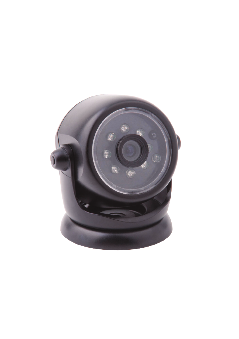
CAMERA REMOVAL
NOTE: This process detailed below should be completed concurrently with the “Device
Removal” process described in section 22.0 of the LR installation and services manual
(60-000249).
1. In the Service menu, scroll to the Removal option and press Select. The handset
screen will display “Insert USB drive”.
2. Insert the USB drive into the USB cable (13-001144). Once the USB drive is
connected and detected by the camera, the image transfer from the camera
memory begins automatically.
NOTE: If the USB key still has les from previous use, the handset screen will display
“USB drive contains data”. Choose the “Delete” option to clear the USB. Image
transfer will then begin.
3. Once the image transfer has begun and is in progress, continue the standard
removal procedure. Once completed, the handset will display “Removal
Complete Connect to PC”.
NOTE: If the standard removal procedure is completed before the image transfer has
completed, a message will appear on the handset indicating that more time is needed.
4. Remove the USB drive and disconnect the handset. Proceed with ITE Removal
Transaction outlined in section 22.5 of the LR installation and services manual
(60-000249).
5. Remove heat shrink and unsolder all wire and ground connection of the camera
Power Harness Cable.
6. Remove camera from mounting surface and use alcohol wipe to eliminate any
residue.
NOTE: If all images are not downloaded from the camera memory during the removal
process, the camera must be sent back to ACS for picture retrieval. The camera will not
allow re-installation to another vehicle prior to being sent back to ACS.
CAMERA EXCHANGE
If the camera is diagnosed as not able to take a picture or communicate during the
install or monitor procedure, an error message will be displayed on the handset screen
followed by a prompt to connect a new camera. Only use new cameras from ACS or
cameras which have been fully cleared of all previous images prior to start installing.
Cameras with les still on them should be sent back to ACS as soon as possible for
retrieval.
In the case of physical damage to a camera, there is an opportunity to exchange the
camera with a new one before the “Connect to PC” message appears during the
Install or Monitor procedures.

ALCOLOCK FOCUS7
TROUBLESHOOTING
The ALCOLOCK V3 device may not accept a breath test and could display error
messages instead. To minimize errors, make sure that the handset is connected
properly, the vehicle battery is in good condition and that mobile phones are not in use
during breath tests. The following is a list of messages (including error messages) that
the handset may display:
ISSUE POSSIBLE CAUSE SOLUTION
ECU is unable to detect
camera
• Camera is defective
• Camera is not connected
• Check connections between
ECU and camera. If problem
persists, use new camera and/
or ECU
No image is displayed on
the handset
• Camera optical system
obstructed
• Camera defective
• Unobstruct view of camera
• Replace camera with new one
Camera is not accepted
at camera exchange
• Camera memory is not
empty
• Camera defective
• Send camera back to ACS and
replace with new one
Camera is not accepted
at install
• Camera memory is not
empty
• Camera defective
• Send camera back to ACS and
replace with new one
USB cable is missing • Camera has been
damaged
• Return to ACS and replace
camera with new one


INM-ENG-60-000619-C
© 2014
Table of contents