Ahlborn ALMEMO 8006-RTA3 User manual

____________________________
Operating instructions
Relay trigger adapter, analog
ALMEMO® 8006-RTA3
V2.4
18.03.2014
www.ahlborn.com

1. Operating controls
1 Operating controls
(1)Sockets P0/1 to P8/9
for ALM MO® clamp connectors
P0/1 2 semiconductor relays R0, R1
P2/3 2 semiconductor relays R2, R3
P4/5 2 analog outputs (option)
P6/7 2 analog outputs (option)
P8/9 2 trigger inputs TR8, TR9
(2) DC socket
Mains adapter
(ZA1312-NA1, 12V, 0.2A)
(3)LCD, graphics display
7 rows for functions
1 line for softkeys F1,◄,▲,►, F2
Shown in brackets : <MENU>
(4) Operating keys
<TR8 / 9> Trigger keys (softkeys)
▲, ▼ P: Port selection
<MENU> Main menu
<☼ON> Switch display illumination ON
▲, ▼, ► F: Function selection
<SET> Direct data selection
PROG Program
▲, ▼, ► P: Data entry
(5) ALMEMO® connecting cable
to measurin instrument, socket A1, A2..
2 Connection diagram
2 ALM MO 8006-RTA3

Contents
3 Contents
1 OPERATING CONTROLS 2
2 CONNECTION DIAGRAM 2
3 FUNCTION OF RELAY TRIGGER ADAPTER, ANALOG 4
4 POWER SUPPLY 4
5 INTERFACE ELEMENTS 4
5 1 Relays 4
5 2 Trigger inputs 5
5 3 Analog outputs 5
5 4 Connecting peripheral equipment 5
6 COMMISSIONING 6
7 DISPLAY AND OPERATING CONTROLS 7
7 1 Main menu 7
7 2 Showing all elements : 7
7 3 Showing single elements : 7
7 4 Device configuration 8
7 5 Messages 9
8 PROGRAMMING VIA THE DEVICE INTERFACE 10
9 ELECTROMAGNETIC COMPATIBILITY 11
10 APPENDIX 11
10 1 Technical data 11
10 2 Product overview Order no 12
10 3 Index 13
10 4 your contact 16
ALM MO® 8006-RTA3 3

4. Function of relay trigger adapter, analog
4 Function of relay trigger adapter, analog
The relay trigger adapter, analog, ZA 8006-RTA3, provides ALM MO® V6 de-
vices (as of 2008 and except 2390) with a universal trigger output interface
with up to 10 interface elements (i.e. maximum 10 semiconductor relays, or 2
trigger inputs, or up to 4 electrically isolated analog outputs).
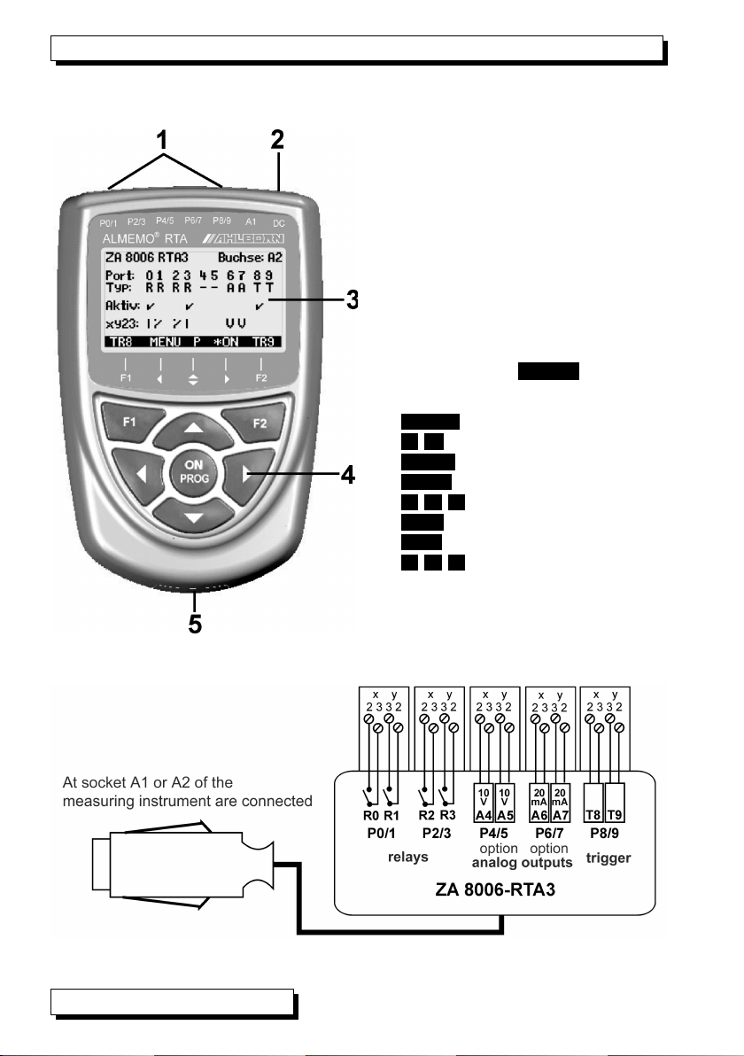
The adapter is connected via the ALM MO® cable to output socket A1 to A5 (if
available) on the ALM MO® devices. All 10 interface elements of each module
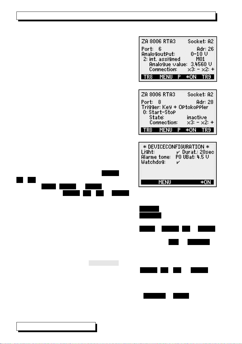
can be individually selected and configured as ports P0 to P9. Programming is
via the ALM MO® device (for a description please refer to the operating in-
structions for the device) or via its interface (for a description please refer to
the Manual, 6.10.9.2). Addressing of the modules and ports is determined on
the basis of the socket into which the module is plugged (see Man. 6.10.9.2) :
Modules in socket A1 : Address 10 to 19
Modules in socket A2 : Address 20 to 29, etc.
5 Power supply
The adapter is supplied with a voltage of 9 to 12 VDC via the measuring instru-
ment. In the standard version the maximum requirement is 35 mA - even with il-
lumination. It is only with optional analog outputs. in particular with electric cur-
rent outputs, that the maximum supply current on the measuring instrument must
take the sensors into consideration. If the maximum supply current is exceeded,
a mains adapter (e.g. ZA1312-NA1) should be connected at the DC socket.
6 Interface elements
Sockets P0/1 and P2/3 are fitted as standard with four semiconductor relays,
normally open type (or changeover type as option); socket P8/9 is fitted as
standard with two trigger inputs.
Sockets P4/5 and P6/7 can (as options) be fitted with analog outputs.
6 1 Relays
The output relays are driven by the measuring instruments automatically in
the event of alarm or by means of interface commands (see Manual 6.10.10). The
function of each relay can be freely set by configuration (see Manual 6.10.9.2).
The assignment of limit value to relay can be programmed in the sensor by the
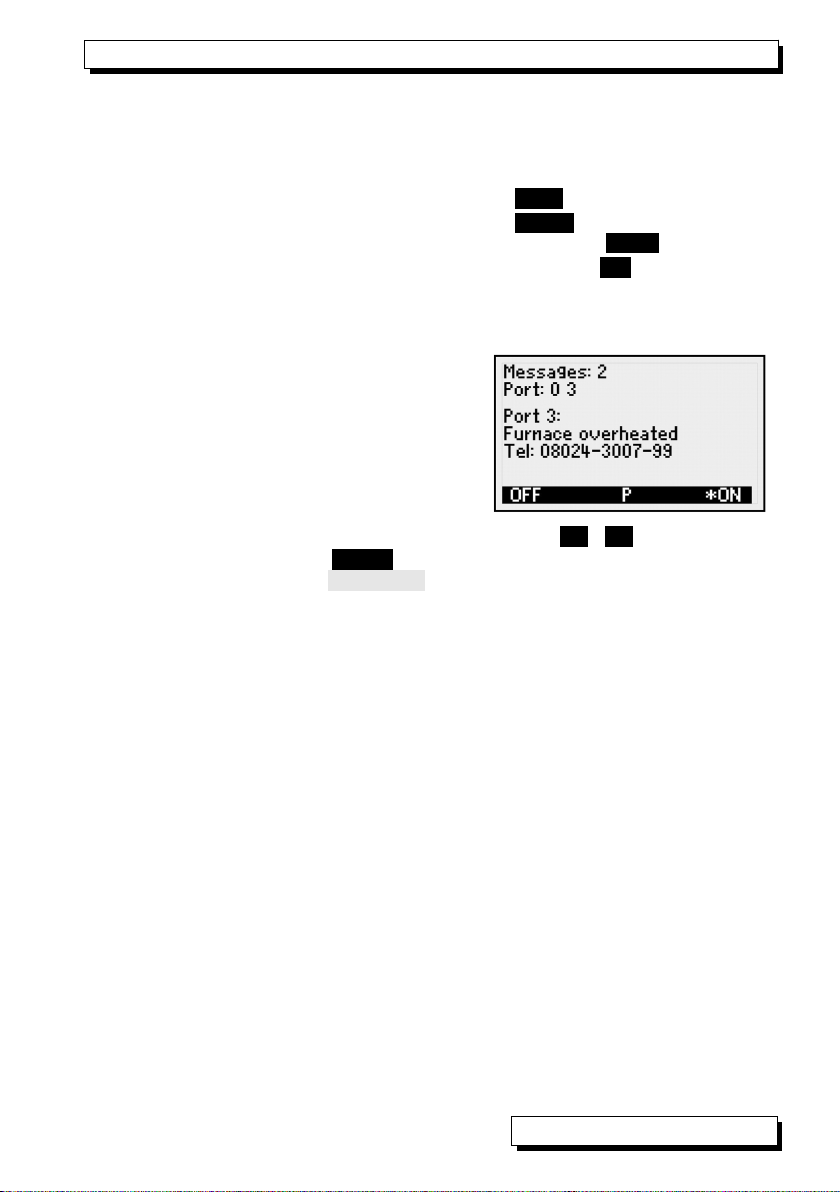
device (see Manual 6.10.8). Whenever a relay is activated a programmable mes-
sage appears and whenever there is a change in status a short acoustic alarm
is sounded. The way in which these relays are driven can be configured by
means of inversion so that they pick up in normal conditions and drop out in
the event of alarm or power failure (see below).
In the following cases it is advisable to connect a mains voltage changeover re-
lay downstream (e.g. Phoenix PLC-RSC-24DC/21, 250V 6A) :
► Current or voltage capacity greater than 50 V, 0.5 A
► For separating the mains voltage side
► For implementing an alarm in the event of failure on the control side
4 ALM MO 8006-RTA3

Relays
6 2 Trigger inputs
The trigger inputs TR8 and TR9 can be driven either via optocouplers by volt-
age levels (4 to 30 V) or via the two keys F1 and F2 (configuration, see 6.3.).
When using floating switch contacts the optocouplers must be appropriately
wired with supply U+ and U-
(see diagram).
The trigger function (as standard to start
or stop a measuring operation) can also
be freely configured (see Manual 6.10.9).
6 3 Analog outputs
The relay adapter can also - in various options - be fitted with electrically iso-
lated analog outputs offering the following signals.
Option Output signal Gain
OA 8000-R2 0.000 to +10.000 V 0.5 mV / digit
or 0.000 to +20.000 mA 1 µA / digit
The output value normally corresponds to the measured value for the selected
measuring point. Or alternatively the analog value can be specified as control
variable via the interface (see Manual 6.10.7). The output signal can be pro-
grammed as standard output 0 to 10 V, 0 to 20 mA, 4 to 20 mA for any partial
measuring ranges (see Manual 6.10.7).
6 4 Connecting peripheral equipment
Peripherals can be connected via the supplied ALM MO screw connector ac-
cording to the following schematic diagram :
ALM MO® 8006-RTA3 5

6. Interface elements
Termi
nals
P0/1
Relay
P2/3
Relay
P4/5
Analog
(option)
P6/7
Analog
(option)
P8/9
Trigger
y1 R1 normally closed (NC)
(option)
R3 normally closed
(option)
(option) (option) U+
y2 R1 common R3 common AO5 + AO7 + TR9+
y3 R1 normally open (NO) R3 normally open AO5 - AO7 - TR9 -
x3 R0 normally open R2 normally open AO4 - AO6 - TR8 -
x2 R0 common R2 common AO4 + AO6 + TR8+
x1 R0 normally closed (option) R2 normally closed (option) U-
7 Commissioning
1. Connect the relay adapter to socket A2 on the ALM MO® device; the integrated
interface elements are then available as port P20 to P29.
2. Switch the ALM MO® device ON; see 5.
3. Connect the peripheral equipment to the clamp connectors and on the relay
adapter to the appropriate port sockets; see 6.4.
4. All the following programming functions can be performed via the device
keypad in the "output modules" menu (if available) or using the AMR-Control
software or by means of a terminal command.
Application Summated alarm :
1. For critical measuring points program limit values on the ALM MO® device.
2. With ALM MO® device program the first relay port to variant 0 ´Summated
alarm´ using command ´i20 f9 k0´ (see Manual 6.10.9.2).
3. In the event of any limit value being overshot the associated relay is acti-
vated.
4. If it is intended that the relay should drop out in the event of an alarm it can be
programmed to operate inversely.
Application Monitoring a measuring point :
1. Program the limit value for the critical measuring point xx on the ALM MO® de-
vice.
2. Program relay yy as limit value action (special function) :
Limit value maximum, command : ´Exx ipp f2 Ryy´,
Limit value minimum, command : ´Exx ipp f3 Ryy´,
The relay is configured automatically to the ´assigned´ variant.
3. If it is intended that the relay should drop out in the event of an alarm it can be
programmed to operate inversely.
Application Driving via the interface :
1. With ALM MO® device in the output modules menu program the relay port
pp to variant 8 ´driven´ using command ´ipp f9 k8´.
2. If it is intended that the relay should drop out in the event of activation it can
be programmed to operate inversely - using the command ´ipp f9 k-8´.
6 ALM MO 8006-RTA3

Commissioning
3. Activate the relay using the command ´ipp f1 Rpp´,
Deactivate the relay using the command ´ipp f1 R-pp´.
Application Driving the analog output :
1. Configure analog output port 6 or 7; see Manual 6.10.7:
e.g. selected analog type x (command ´ipp f9 Ax´)
assigning to the selected measuring point (command ´ipp f9 E-00´)
or assigning to any reference channel xx (command ´ipp f9 Exx´)
or output the value yyyyy via the interface (command ´ipp f9 ayyyyy´)
2. Define the desired measuring range for the measuring point, to be output
over the whole analog output range (0 to 10 V or 0 to 20 mA), using the pa -
rameters analog start and analog end in sensor programming, special func-
tions, see Manual 6.10.7.
3. If for a current output the output range 4 to 20 mA is to be used (instead of 0
to 20 mA), the element flag for 4 to 20 mA must be activated for the appro-
priate measuring point; see Manual 6.10.3.
8 Display and operating controls
The adapter incorporates a graphics display that can show exactly all states
affecting the interface elements. This is configured largely by the device itself.
8 1 Main menu
The main menu is called up by pressing
<MENU>). Here, by pressing ▲ / ▼ , you can
access menu items Allports or Singleports
or Deviceconfigurationand then, by press-
ing ► or )PROG), activate these.
By means of <☼ON>) you can switch on dis-
play illumination.
8 2 Showing all elements :
Below the port number the type of elements
available is shown with its abbreviation. Below
this the activation status of the relays and trig-
ger inputs is shown and in line xy23 the actual
switching status of the relays and the type of
analog outputs.
8 3 Showing single elements :
You can by pressing ▲ and ▼ scroll
through and select any port individually and
display details of address, element type, vari-
ant, and status.
With relays one can also see the actual
switching status of the individual contacts.
ALM MO® 8006-RTA3 7

8. Display and operating controls
Analog outputs
For analog outputs, the analog output type,
the assigned measurement loop (reference
channel) and the effective output signal are
displayed at the corresponding terminals.
Trigger inputs
With trigger inputs the configurable trigger
source can be seen on the device itself; the
fields that follow show the trigger function, the
activation status, and the contact assignment
in the plug connector; this information if help-
ful when connecting.
8 4 Device configuration
In this menu the display illumination and the
internal alarm signaling device can be config-
ured and, if necessary, the watchdog function
can be activated. The desired function can be
selected by means of keys )PROG) and
▲ / ▼ . Programming is by means of the
softkeys <ON> , <OFF> )or <SET> and input is
by means of keys )PROG), ▲ / ▼ ..., )PROG).
Illumination
To switch display illumination ON press : <☼ON>) Illumination
To switch display illumination OFF press <☼OFF>) Illumination-
To save battery consumption the duration Duration:20seconds
of display illumination can be set by means of : <SET> or )PROG), ▲ ..., )PROG)
To switch illumination ON permanently, Symbol: - -
To switch back ON again without this function press ON) or )<MENU>)
Alarm tone
Normal short alarm tone on each change : Symbol: ON)
Having selected the function Alarmtone
the beeper can be reprogrammed by means of : )PROG), ▲ / ▼ ..., )PROG)
e.g switched off by means of : Symbol: OFF)
Assign relay ports configured in any way : Symbol: Px)
In permanent alarm status : Symbol: `Px´) flashes.
To switch this signal OFF press ( )<MENU>) ), <OFF> )
8 ALM MO 8006-RTA3

Device configuration
Watchdog
The watchdog function ensures that all relays drop out if the control of the
measuring instrument or of controlled relays via the interface fails for a duration
of 60 seconds, normally displayed as a watchdog alarm.
To switch the watchdog function ON press : <ON>
To switch the watchdog function OFF press : <OFF>)
Watchdog alarm display: Watchdog:ERROR
Changing the Watchdog Duration: s.o. Duration:060s
Switch off watchdog alarm with watchdog function and switch on again after
restoring the control.
8 5 Messages
ach relay can be assigned a particular
message - either via the AMR-Control soft-
ware or a terminal; as soon as such a relay
is activated the associated message will ap-
pear in the display in its own window. If sev-
eral relays are active, you can leaf up and
down through the associated messages by pressing ▲ / ▼ . These windows
can be closed by pressing <OFF>) but can be reopened at any time via main
menu (see 6.1), menu item essages.
ALM MO® 8006-RTA3 9

9. Programming via the device interface
9 Programming via the device interface
The programming of the output ports with all variants is described in chapters
6.7, 6.9 and 6.10 of the manual. Here only an addition:
The port address pp is determined on the basis of the socket into which the
module is plugged :
Modules in socket A1 : Port address pp = 10 to 19
Modules in socket A2 : Port address pp = 20 to 29
etc.
Function Interface command
Port pp, relay variant, driven normally ipp f9 k8
Port pp, relay variant, driven inversely : ipp f9 k-8
To activate relay port pp f1 Rpp
To deactivate relay port pp f1 R-pp
To set analog value of analog output port pp ipp f9 ayyyyy
Program message for port pp (e.g.): ipp $message-port pp
Start new line with special character ´|´: |Tel: 123 <CRLF>
To output message :
Response
ipp P 8
Message port pp
Tel: 123 <CRLF>
To output programming and status f3 P19
Response
Output module A2.ZA8006RTA3
Pxx Interface element Variant Status Contact
00 Normally open 0.5 A Driven Inactive Open 00:NO0 8 0 O
01 Normally open 0.5 A Driven inversely Inactive Closed 01:NO0-8 0 C
02 Normally closed 0.5 A Driven Inactive Closed 02:NC0 8 0 C
03 Chan eover 0.5 A Driven inversely Active Open 02:CO0-8 1 O
06 Analo output 10 V Driven by value 06:AO5 COM +08.3 5 V
07 Analo output 20 mA Driven by value 07:AO6 COM +12.3 5mA
08 Tri er key Start / stop 08:TR1 0
09 Tri er Optocoupler Manual 09:TR2 1
NO=Normally open
NC=Normally closed
CO=Chan eover
10 ALM MO 8006-RTA3

lectromagnetic compatibility
10 Electromagnetic compatibility
We, Ahlborn Mess- und Regelungstechnik GmbH, hereby declare that the
ALM MO® 8006-RTA3 device bears the C mark and complies with the provi-
sions of the Low Voltage Directive and the essential protection requirements of
the 89/336/ C lectromagnetic Compatibility Directive. The following stan-
dards were used to assess the product:
Security: N 61010-1: 2001
MC N 61326: 2006
If the product is changed without our consent, this declaration will lose its validity.
11 Appendix
11 1 Technical data
Relay : Semiconductor relay, 1 ohm Load capacity : 50 V,
0.5 A
Trigger inputs : Optocoupler 4 to 30 V Input current 2 mA
Analog outputs : lectrically isolated, switchable
OA 8006-R02 -4.00 to +10.0 V 0.5 mV / digit Load > 100 kW
0.0 to +20.0 mA 1 µA / digit Load < 500 W
Accuracy: ± 0.1% of measured value ± 0.1% of final value
Temperature drift : 10 ppm / K
Time constant : 100 us
Power supply : 9 to 12 VDC from the measuring instrument
Current consumption : Standard approx. 10 mA, with illumination approx. 25 mA
Per 2 analog outputs approx. 40 mA + 1.75 x IOUT
Standard equipment : Graphics display 126 x 64 (55 x 30 mm)
7 silicone keys
Housing: (LxWxH) 127 x 83 x 42 mm ABS (acrylonitrile buta-
diene styrene), weight : approx. 260 g
Suitable conditions :
Operating temperature : -10 to +50 °C (storage temperature : -20 to +60 °C)
Ambient relative humidity : 10 to 90 % RH (non-condensing)
ALM MO® 8006-RTA3 11

11. Appendix
11 2 Product overview Order no.
ALMEMO® relay trigger adapter
with 2 trigger inputs, 4 normally open relays, graphics display
and keypad, including 1.5-meter ALM MO® connecting cable
and 3 ALM MO® clamp connectors ZA 8006-RTA3
Mains adapter with ALM MO connector, 12 V, 1 A ZA 1312-NA8
Options :
2 additional relays (maximum 10),
including 1 ALM MO® clamp connector OA 8006-SH2
2 additional normally closed relays per relay pair OA 8006-OH2
2 analog outputs electrically isolated 0..10V or 0..20mA selectable,
incl. 1 ALM MO® clamp connector OA 8006-R02
Fixture for top-hat rail mounting ZB 2490-HS
12 ALM MO 8006-RTA3

Index
11 3 Index
Accuracy 11.1 11
activation status 8.2 7
Active 9 10
Addressing 4 4
Alarm tone 8.4 8
All ports 8.1 7
Ambient relative humidity 11.1 11
analog outputs 6.3 5
Analog outputs 8.3 8
Analog outputs 11.1 11
Appendix 11 11
Changeover 9 10
Changeover 9 10
clamp connectors 7 6
Closed 9 10
command 9 10
Commissioning 7 6
Connecting peripheral equipment 6.4 5
Connection diagram 2 2
contact assignment 8.3 8
Current consumption 11.1 11
Device configuration 8.4 8
Display and operating controls 8 7
display illumination 8.4 8
driven inversely 9 10
Driving the analog output 7 7
Driving via the interface 7 6
duration 8.4 8
lectromagnetic compatibility 10 11
Function of relay trigger adapter, analog 4 4
Housing 11.1 11
Illumination 8.4 8
Inactive 9 10
Interface 9 10
Interface elements 6 4
inversion 6.1 4
key 9 10
Load capacity 11.1 11
Main menu 8.1 7
mains adapter 5 4
Mains adapter with 11.2 12
Messages 8.5 9
ALM MO® 8006-RTA3 13

11. Appendix
Messages 8.5 9
Monitoring a measuring point 7 6
Normally closed 9 10
normally closed relays 11.2 12
Normally open 9 10
normally open 11.2 12
Open 9 10
Operating controls 1 2
Operating temperature 11.1 11
Options 11.2 12
Optocoupler 9 10
Optocoupler 11.1 11
ormally closed (NC) 6.4 6
ormally open (NO) 6.4 6
output relays 6.1 4
port 7 4, 6
port address 9 10
Power supply 5 4
Power supply 11.1 11
Product overview 11.2 12
Programming via the device interface 9 10
Relay 11.1 11
relays 8.3 7
screw connector 6.4 5
Showing all elements 8.2 7
Showing single elements 8.3 7
Single ports 8.1 7
Standard equipment 11.1 11
status 8.3 7
Suitable conditions 11.1 11
Summated alarm 7 6
switching status 8.3 7
Technical data 11.1 11
Temperature drift 11.1 11
terminal command 7 6
Time constant 11.1 11
To output message 9 10
top-hat rail mounting 11.2 12
Trigger 9 10
Trigger inputs 8.3 5, 8
trigger inputs 6.2 5
Trigger inputs 11.1 11
14 ALM MO 8006-RTA3

Index
trigger source 8.3 8
variant 8.3 7
voltage capacity 6.1 4
Watchdog 8.4 9
8.4 8
ALM MO® 8006-RTA3 15

11. Appendix
11 4 your contact
16 ALM MO 8006-RTA3
Table of contents