CHAPTER ⅢOPERATION
CAUTION: Be familiar with the machine before starting. Read this manual
carefully to learn how to operate the machine safely and how
to set it to provide maximum field efficiency.
3.1 Checking Before Operating
ATTENTION: Only use universal joint conforming to CE standard and
protect them properly.
Before operating the machine, the following areas should be checked off:
1. Pay attention to the warning stickers on each greasing point. Before starting the
machine, please make sure lubricate each grease point with grease or oil
according to requirement on the warning stickers.
2. Use only an agricultural tractor of horsepower within limits of the machine specified.
3. Check that the machine is properly attached to the tractor. Be sure retainers are used
on the mounting pins.
4. Be sure extra weights are mounted on the front of the tractor.
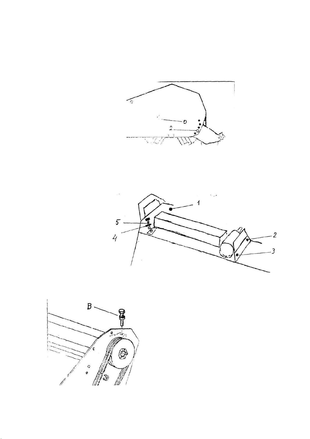
5. Check the oil level in the gearbox. Add as required.
6. Check that the tractor PTO shaft turns freely and that the machine driving shaft can
telescope easily.
7. Check the blades. Be sure they are not damaged or broken and swing freely in their
mount. Repair or replace as required.
8. Check and tighten the blade bolts.
9. Check for entangled material in all rotating parts. Remove this material.
10. Install and secure all guards, doors and covers before starting.
11. Before installing the universal joint, the tractor and the machine motor shall be
stopped and the key be taken away. The universal joints shall be installed in good
state, with proper protective parts.
12. The chain on the protective parts of the universal joint shall be guaranteed in good
condition, in case, automatic rotation occurs.
13. All other persons shall leave the ground before connecting the driving power from the
tractor. Keep the output of the tractor at 540 RPM.
14. Before cleaning, repairing and lubricating the machine, stop the motor and take away
the key with you.
15. When the universal joint is not connected with the tractor, they must be connected
again through the frame to protect the joint from damaging.
16. Don’t approach the machine when the machine runs.
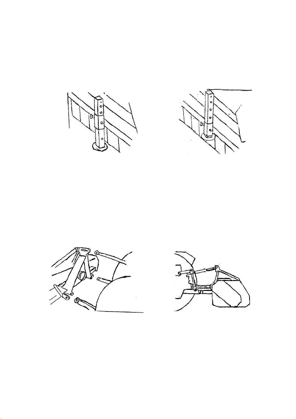
3.2 Adjusting the Height
In order to conduct a precise work, the machine shall be operated according to the
recommended cutting height.
For saving fuel and power, and reducing the wear of the machine, the cutting height must