Aire-Flo 92AF1UH User manual

Page 1
08/12
*2P0812*
507078−01
*P507078-01*
P.O. Box 799900, Dallas, TX 75379−9900
INSTALLATION INSTRUCTIONS
92AF1UH and 95AF1UH
Warm Air Gas Furnaces
Upflow/Horizontal Left and Right Air Discharge
This is a safety alert symbol and should never be ignored. When you see this symbol on labels or in
manuals, be alert to the potential for personal injury or death.
This manual must be left with the homeowner for future reference.
CAUTION
As with any mechanical equipment, personal injury
can result from contact with sharp sheet metal
edges. Be careful when you handle this equipment.
WARNING
Improper installation, adjustment, alteration, service
or maintenance can cause property damage, person-
al injury or loss of life. Installation and service must
be performed by a licensed professional installer (or
equivalent), service agency or the gas supplier.
Unit Dimensions 2. . . . . . . . . . . . . . . . . . . . . . . . . . . . . . . . .
92AF1UH/95AF1UH Gas Furnace 3. . . . . . . . . . . . . . . . . .
Shipping and Packing List 3. . . . . . . . . . . . . . . . . . . . . . . . .
Safety Information 3. . . . . . . . . . . . . . . . . . . . . . . . . . . . . . . .
Use of Furnace as a Construction Heater 4. . . . . . . . . . . .
General 5. . . . . . . . . . . . . . . . . . . . . . . . . . . . . . . . . . . . . . . . .
Combustion, Dilution, Ventilation Air 5. . . . . . . . . . . . . . . .
Setting Equipment 8. . . . . . . . . . . . . . . . . . . . . . . . . . . . . . . .
Filters 12. . . . . . . . . . . . . . . . . . . . . . . . . . . . . . . . . . . . . . . . . .
Duct System 12. . . . . . . . . . . . . . . . . . . . . . . . . . . . . . . . . . . .
Pipe and Fittings Specifications 12. . . . . . . . . . . . . . . . . . .
Joint Cementing Procedure 14. . . . . . . . . . . . . . . . . . . . . . .
Venting Practices 15. . . . . . . . . . . . . . . . . . . . . . . . . . . . . . . .
Vent Piping Guidelines 16. . . . . . . . . . . . . . . . . . . . . . . . . . .
Gas Piping 33. . . . . . . . . . . . . . . . . . . . . . . . . . . . . . . . . . . . .
Electrical 35. . . . . . . . . . . . . . . . . . . . . . . . . . . . . . . . . . . . . . .
Unit Start Up 38. . . . . . . . . . . . . . . . . . . . . . . . . . . . . . . . . . . .
Gas Pressure Measurement 40. . . . . . . . . . . . . . . . . . . . . .
Proper Combustion 40. . . . . . . . . . . . . . . . . . . . . . . . . . . . . .
High Altitude 40. . . . . . . . . . . . . . . . . . . . . . . . . . . . . . . . . . . .
Other Unit Adjustments 42. . . . . . . . . . . . . . . . . . . . . . . . . .
Service 43. . . . . . . . . . . . . . . . . . . . . . . . . . . . . . . . . . . . . . . .
Integrated Control Fault Codes 44. . . . . . . . . . . . . . . . . . . .
Repair Parts List 44. . . . . . . . . . . . . . . . . . . . . . . . . . . . . . . .
Start Up Checklist 45. . . . . . . . . . . . . . . . . . . . . . . . . . . . . . .
TABLE OF CONTENTS
Supersedes 506720−01

Page 2
92AF1UH and 95AF1UH Unit Dimensions − inches (mm)
2
Optional External Side Return Air Filter Kit is not for use
with the optional Return Air Base.
1. Single side return air with transition, to accommodate
20 x 25 x 1 in. (508 x 635 x 25 mm) cleanable air
filter. Required to maintain proper air velocity.
2. Single side return air with optional Return Air Base
3. Bottom return air.
4. Return air from both sides.
5. Bottom and one side return air.
See Blower Performancetables for additional information.
1
NOTE −20C and 20D size units that require air
volumes 1800 cfm or over (850 L/s) must have
one of the following
A B C D
in. mm in. mm in. mm in. mm
17−1/2 446 16−3/8 416 16 406 7−5/8 194
21 533 19−7/8 505 19−1/2 495 9−3/8 238
24−1/2 622 23−3/8 594 23 584 11−1/8 283
Model No.
92AF1UH135P20D
95AF1UH045P08B
92AF1UH045P12B
92AF1UH070P08B
92/95UH1070P12B
95AF1UH09012B
92AF1UH090P12C
92/95AF1UH090P16C
92AF1UH110P16C
92/95AF1UH110P20C
6−9/16 (167)
Left
9 (229)
Right
23
(584)
(19)
3/4
(
19)
1Bottom Return
Air Opening
GAS PIPING INLET
(Either Side)
Side Return
Air Opening
(Either Side)
1Bottom Return
Air Opening
EXHAUST AIR
OUTLET
ELECTRICAL
INLET
(Either Side)
SUPPLY AIR
OPENING
FRONT VIEW SIDE VIEW
TOP VIEW
A
B9/16 (14)
C
3
/4
27−3/4
(705)
19−7/16
(494)
23−1/2
(597)
1−1/2
(38)
6−1/2 (165)
(Either Side)
33
(838)
3−3/8
(86)
1−15/16 (49)
14
(356)
9/16
(14)
12−5/8 (321)
(Either Side)
2OPTIONAL
SIDE RETURN
AIR FILTER KIT
(Either Side)
16
(406)
14−3/4
(375)
2OPTIONAL
SIDE RETURN
AIR FILTER KIT
(Either Side)
5/8
(16)
1
3−1/4
(83)
23−3/4
(603)
25
(635)
D
Front Panel
COMBUSTION
AIR INTAKE
2 (51)
(Either Side)
2 (51)
CONDENSATE
TRAP CONNECTION
(Either Side)
2−7/8
(73)
AIR FLOW
3/4 (19)

Page 3
92AF1UH and 951UH Gas Furnace
The 92AF1UH and 95AF1UH Category IV gas furnaces
are shipped ready for installation in the upflow or horizon-
tal position. Each furnace is shipped with the bottom panel
in place. The bottom panel must be removed if the unit is to
be installed in horizontal or upflow applications with bot-
tom return air.
The 92AF1UH and 95AF1UH can be installed as either a
Direct Vent or a Non−Direct Vent gas central furnace.
Each furnace is equipped for installation in natural gas ap-
plications. A conversion kit (ordered separately) is re-
quired for use in propane/LP gas applications.
NOTE − In Direct Vent installations, combustion air is taken
from outdoors and flue gases are discharged outdoors. In
Non−Direct Vent installations, combustion air is taken from
indoors and flue gases are discharged outdoors. See figure
1 for applications involving roof termination.
Shipping and Packing List
Package 1 of 1 contains
1 − Assembled Gas Furnace
1 − Bag assembly containing the following:
3 − Wire nuts
1 − Snap bushing
1 − Snap plug
1 − Wire tie
1 − Condensate trap
1 − Condensate trap cap
1 − Condensate trap clamp
1 − 2" diameter debris screen
1 − 3/4" Threaded street elbow
Check equipment for shipping damage. If you find any
damage, immediately contact the last carrier.
The following items may also be ordered separately:
1 − Thermostat
1 − Propane/LP changeover kit
1 − Return air base kit
1 − Horizontal suspension kit
FIGURE 1
DIRECT VENT INSTALLATION NON−DIRECT VENT
INSTALLATION
EXHAUST
OUTLET
COMBUSTION
AIR INTAKE INSIDE
OF HOUSE
EXHAUST
OUTLET
COMBUSTION
AIR INTAKE
OUTSIDE OF
HOUSE
Safety Information
WARNING
Improper installation, adjustment, alteration, service
or maintenance can cause property damage,
personal injury or loss of life. Installation and service
must be performed by a licensed professional in-
staller (or equivalent), service agency or the gas sup-
plier.
CAUTION
As with any mechanical equipment, personal injury
can result from contact with sharp sheet metal
edges. Be careful when you handle this equipment.
DANGER
Danger of explosion.
There are circumstances in which odorant used with
LP/propane gas can lose its scent. In case of a leak,
LP/propane gas will settle close to the floor and may
be difficult to smell. An LP/propane leak detector
should be installed in all LP applications.
Use only the type of gas approved for use with this furnace.
Refer to unit nameplate.
92AF1UH and 95AF1UH units are CSA International certi-
fied to ANSI Z21.47 and CSA 2.3 standards.
Building Codes
In the USA, installation of gas furnaces must conform with lo-
cal building codes. In the absence of local codes, units must
be installed according to the current National Fuel Gas Code
(ANSI-Z223.1/NFPA 54). The National Fuel Gas Code is
available from the following address:
American National Standards Institute, Inc.
11 West 42nd Street
New York, NY 10036
In Canada, installation must conform with current National
Standard of Canada CSA-B149 Natural Gas and Propane
Installation Codes, local plumbing or waste water codes
and other applicable local codes.
In order to ensure proper unit operation in non−direct vent
applications, combustion and ventilation air supply must be
provided according to the current National Fuel Gas Code
or CSA-B149 standard.

Page 4
Installation Locations
This furnace is CSA International certified for installation
clearances to combustible material as listed on the unit
nameplate and in the table in figure 9. Accessibility and ser-
vice clearances must take precedence over fire protection
clearances.
NOTE − For installation on combustible floors, the furnace
shall not be installed directly on carpeting, tile, or other
combustible material other than wood flooring.
For installation in a residential garage, the furnace must
be installed so that the burner(s) and the ignition source
are located no less than 18 inches (457 mm) above the
floor. The furnace must be located or protected to avoid
physical damage by vehicles. When a furnace is installed
in a public garage, hangar, or other building that has a haz-
ardous atmosphere, the furnace must be installed accord-
ing to recommended good practice requirements and cur-
rent National Fuel Gas Code or CSA B149 standards.
NOTE − Furnace must be adjusted to obtain a temperature
rise within the range specified on the unit nameplate. Failure
to do so may cause erratic limit operation and premature heat
exchanger failure.
This furnace must be installed so that its electrical compo-
nents are protected from water.
Installed in Combination with a Cooling Coil
When this furnace is used with cooling coils (figure 2), it shall
be installed in parallel with, or on the upstream side of, cool-
ing coils to avoid condensation in the heating compartment.
With a parallel flow arrangement, a damper (or other means
to control the flow of air) must adequately prevent chilled air
from entering the furnace. If the damper is manually oper-
ated, it must be equipped to prevent operation of either the
heating or the cooling unit, unless it is in the full HEAT or
COOL setting.
When installed, this furnace must be electrically grounded
according to local codes. In addition, in the United States,
installation must conform with the current National Electric
Code, ANSI/NFPA No. 70. The National Electric Code
(ANSI/NFPA No. 70) is available from the following ad-
dress:
National Fire Protection Association
1 Battery March Park
Quincy, MA 02269
In Canada, all electrical wiring and grounding for the unit
must be installed according to the current regulations of the
Canadian Electrical Code Part I (CSA Standard C22.1)
and/or local codes.
FIGURE 2
Gas Unit
Heating Unit Installed Upstream of Cooling Coil
Gas Unit
Dampers
(open during heating operation only)
Dampers
(open during cooling operation only)
Heating Unit Installed Parallell to Air Handler Unit
Air Handler Unit
Cooling Coil
AIR FLOWAIR FLOW
AIR FLOW AIR FLOW
NOTE − This furnace is designed for a minimum continu-
ous return air temperature of 60°F (16°C) or an intermit-
tent operation down to 55°F (13°C) dry bulb for cases
where a night setback thermostat is used. Return air tem-
perature must not exceed 85°F (29°C) dry bulb.
The furnace may be installed in alcoves, closets, attics,
basements, garages, crawl spaces and utility rooms in the
upflow or horizontal position.
This furnace design has not been CSA certified for installa-
tion in mobile homes, recreational vehicles, or outdoors.
Use of Furnace as Construction Heater
These units are not recommended for the use of a
construction heater during any phase of construction. Very
low return air temperatures, harmful vapors and operation
of the unit with clogged or misplaced filters will damage the
unit.
These units may be used for heating of buildings or struc-
tures under construction, if the following conditions are
met:
DThe vent system must be permanently installed per
these installation instructions.
DA room thermostat must control the furnace. The use of
fixed jumpers that will provide continuous heating is not
allowed.
DThe return air duct must be provided and sealed to the
furnace.
DReturn air temperature range between 60°F (16°C) and
80°F (27°C) must be maintained.

Page 5
DAir filters must be installed in the system and must be
maintained during construction.
DAir filters must be replaced upon construction comple-
tion.
DThe input rate and temperature rise must be set per the
furnace rating plate.
DOne hundred percent (100%) outdoor air must be pro-
vided for combustion air requirements during construc-
tion. Temporary ducting may supply outdoor air to the
furnace. Do not connect duct directly to the furnace.
Size the temporary duct following these instructions in
section for Combustion, Dilution and Ventilation Air in a
confined space with air from outside.
DThe furnace heat exchanger, components, duct system,
air filters and evaporator coils must be thoroughly
cleaned following final construction clean−up.
DAll furnace operating conditions (including ignition, in-
put rate, temperature rise and venting) must be verified
according to these installation instructions.
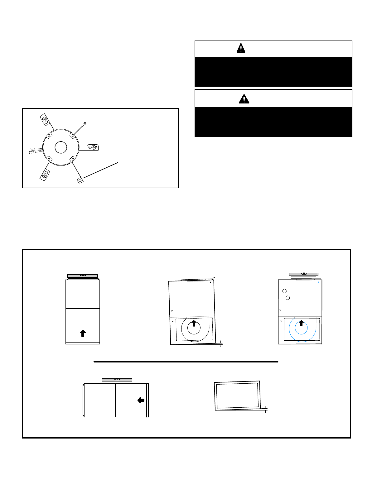
General
These instructions are intended as a general guide and do
not supersede local codes in any way. Consult authorities
having jurisdiction before installation.
In addition to the requirements outlined previously, the fol-
lowing general recommendations must be considered
when installing this furnace:
•Place the furnace as close to the center of the air dis-
tribution system as possible. The furnace should also be
located close to the vent termination point.
•When the furnace is installed in non−direct vent applica-
tions, do not install the furnace where drafts might blow
directly into it. This could cause improper combustion
and unsafe operation.
•When the furnace is installed in non−direct vent applica-
tions, do not block the furnace combustion air opening
with clothing, boxes, doors, etc. Air is needed for proper
combustion and safe unit operation.
•When the furnace is installed in an attic or other insu-
lated space, keep insulation away from the furnace.
•When the furnace is installed in an unconditioned
space, consider provisions required to prevent freezing
of condensate drain system.
CAUTION
This furnace should not be installed in areas nor-
mally subject to freezing temperatures.
WARNING
The State of California has determined that this prod-
uct may contain or produce a chemical or chemicals,
in very low doses, which may cause serious illness
or death. It may also cause cancer, birth defects or re-
productive harm.
WARNING
Insufficient combustion air can cause headaches,
nausea, dizziness or asphyxiation. It will also cause
excess water in the heat exchanger resulting in rust-
ing and premature heat exchanger failure. Excessive
exposure to contaminated combustion air will result
in safety and performance related problems. Avoid
exposure to the following substances in the com-
bustion air supply:
Permanent wave solutions
Chlorinated waxes and cleaners
Chlorine base swimming pool chemicals
Water softening chemicals
De−icing salts or chemicals
Carbon tetrachloride
Halogen type refrigerants
Cleaning solvents (such as perchloroethylene)
Printing inks, paint removers, varnishes, etc.
Hydrochloric acid
Cements and glues
Antistatic fabric softeners for clothes dryers
Masonry acid washing materials
Combustion, Dillution & Ventilation Air
If the furnace is installed as a Non−Direct Vent Fur-
nace, follow the guidelines in this section.
NOTE − In Non−Direct Vent installations, combustion air
is taken from indoors and flue gases are discharged out−
doors.
In the past, there was no problem in bringing in sufficient
outdoor air for combustion. Infiltration provided all the air
that was needed. In today’s homes, tight construction
practices make it necessary to bring in air from outside
for combustion. Take into account that exhaust fans, ap-
pliance vents, chimneys, and fireplaces force additional
air that could be used for combustion out of the house.
Unless outside air is brought into the house for combus-
tion, negative pressure (outside pressure is greater than
inside pressure) will build to the point that a downdraft
can occur in the furnace vent pipe or chimney. As a result,
combustion gases enter the living space creating a po-
tentially dangerous situation.

Page 6
In the absence of local codes concerning air for combus−
tion and ventilation, use the guidelines and procedures in
this section to install 92AF1UH/95AF1UH furnaces to
ensure efficient and safe operation. You must consider
combustion air needs and requirements for exhaust
vents and gas piping. A portion of this information has
been reprinted with permission from the National Fuel
Gas Code (ANSI− Z223.1/NFPA 54). This reprinted ma-
terial is not the complete and official position of the ANSI
on the referenced subject, which is represented only by
the standard in its entirety.
In Canada, refer to the CSA B149 installation codes.
CAUTION
Do not install the furnace in a corrosive or contami-
nated atmosphere. Meet all combustion and ventila-
tion air requirements, as well as all local codes.
All gas-fired appliances require air for the combustion pro-
cess. If sufficient combustion air is not available, the fur-
nace or other appliance will operate inefficiently and un-
safely. Enough air must be provided to meet the needs of all
fuel−burning appliances and appliances such as exhaust
fans which force air out of the house. When fireplaces, ex-
haust fans, or clothes dryers are used at the same time as
the furnace, much more air is required to ensure proper
combustion and to prevent a downdraft. Insufficient air
causes incomplete combustion which can result in carbon
monoxide.
In addition to providing combustion air, fresh outdoor air di-
lutes contaminants in the indoor air. These contaminants
may include bleaches, adhesives, detergents, solvents
and other contaminants which can corrode furnace compo-
nents.
The requirements for providing air for combustion and ven-
tilation depend largely on whether the furnace is installed in
an unconfined or a confined space.
Unconfined Space
An unconfined space is an area such as a basement or
large equipment room with a volume greater than 50 cubic
feet (1.42 m3) per 1,000 Btu (.29 kW) per hour of the com-
bined input rating of all appliances installed in that space.
This space also includes adjacent rooms which are not
separated by a door. Though an area may appear to be un-
confined, it might be necessary to bring in outdoor air for
combustion if the structure does not provide enough air by
infiltration. If the furnace is located in a building of tight
construction with weather stripping and caulking around
the windows and doors, follow the procedures in the Air
from Outside section.
Confined Space
A confined space is an area with a volume less than 50 cubic
feet (1.42 m3) per 1,000 Btu (.29 kW) per hour of the com−
bined input rating of all appliances installed in that space. This
definition includes furnace closets or small equipment rooms.
When the furnace is installed so that supply ducts carry air
circulated by the furnace to areas outside the space con-
taining the furnace, the return air must be handled by ducts
which are sealed to the furnace casing and which terminate
outside the space containing the furnace. This is especially
important when the furnace is mounted on a platform in a
confined space such as a closet or small equipment room.
Even a small leak around the base of the unit at the platform
or at the return air duct connection can cause a potentially
dangerous negative pressure condition. Air for combustion
and ventilation can be brought into the confined space ei-
ther from inside the building or from outside.
Air from Inside
If the confined space that houses the furnace adjoins a
space categorized as unconfined, air can be brought in by
providing two permanent openings between the two
spaces. Each opening must have a minimum free area of 1
square inch (645 mm2) per 1,000 Btu (.29 kW) per hour of
total input rating of all gas−fired equipment in the confined
space. Each opening must be at least 100 square inches
(64516 mm2). One opening shall be within 12 inches (305
mm) of the top of the enclosure and one opening within 12
inches (305 mm) of the bottom. See figure 3.
FIGURE 3
EQUIPMENT IN CONFINED SPACE − ALL AIR FROM INSIDE
OPENINGS
(To Adjacent
Unconfined
Space)
NOTE − Each opening shall have a free area of at least one square inch
per 1,000 Btu (645mm2per .29kW) per hour of the total input rating of
all equipment in the enclosure, but not less than 100 square inches
(64516mm.2).
ROOF TERMINATED
EXHAUST PIPE
SIDE WALL
TERMINATED
EXHAUST PIPE
(ALTERNATE
LOCATION)
Air from Outside
If air from outside is brought in for combustion and ventila-
tion, the confined space shall be provided with two perma-
nent openings. One opening shall be within 12" (305mm)
of the top of the enclosure and one within 12" (305mm) of
the bottom. These openings must communicate directly

Page 7
or by ducts with the outdoors or spaces (crawl or attic) that
freely communicate with the outdoors or indirectly
through vertical ducts. Each opening shall have a mini-
mum free area of 1 square inch per 4,000 Btu (645mm2
per 1.17kW) per hour of total input rating of all equipment
in the enclosure. When communicating with the outdoors
through horizontal ducts, each opening shall have a mini-
mum free area of 1 square inch per 2,000 Btu (645mm2
per .59kW) per total input rating of all equipment in the en-
closure (See figure 4).
FIGURE 4
EQUIPMENT IN CONFINED SPACE − ALL AIR FROM OUTSIDE
(Inlet Air from Crawl Space and Outlet Air to Ventilated Attic)
NOTE−The inlet and outlet air openings shall each have a free area
of at least one square inch per 4,000 Btu (645mm2per 1.17kW) per
hour of the total input rating of all equipment in the enclosure.
OUTLET
AIR
INLET
AIR
VENTILATION
LOUVERS
(For unheated
crawl space)
FURNACE
ROOF TERMINATED
EXHAUST PIPE
VENTILATION LOUVERS
(Each end of attic)
SIDE WALL
TERMINATED
EXHAUST PIPE
(ALTERNATE
LOCATION)
If air from outside is brought in for combustion and ventila-
tion, the confined space must have two permanent open-
ings. One opening shall be within 12 inches (305 mm) of
the top of the enclosure and one opening within 12 inches
(305 mm) of the bottom. These openings must communi-
cate directly or by ducts with the outdoors or spaces (crawl
or attic) that freely communicate with the outdoors or indi-
rectly through vertical ducts. Each opening shall have a
minimum free area of 1 square inch (645 mm2) per 4,000
Btu (1.17 kW) per hour of total input rating of all equipment
in the enclosure. See figures 4 and 5. When communicat-
ing with the outdoors through horizontal ducts, each open-
ing shall have a minimum free area of 1 square inch (645
mm2) per 2,000 Btu (.56 kW) per total input rating of all
equipment in the enclosure. See figure 6.
When ducts are used, they shall be of the same cross−sec-
tional area as the free area of the openings to which they
connect. The minimum dimension of rectangular air ducts
shall be no less than 3 inches (75 mm). In calculating free
area, the blocking effect of louvers, grilles, or screens
must be considered. If the design and free area of protec-
tive covering is not known for calculating the size opening
required, it may be assumed that wood louvers will have
20 to 25 percent free area and metal louvers and grilles
will have 60 to 75 percent free area. Louvers and grilles
must be fixed in the open position or interlocked with the
equipment so that they are opened automatically during
equipment operation.
FIGURE 5
EQUIPMENT IN CONFINED SPACE − ALL AIR FROM OUTSIDE
(All Air Through Ventilated Attic)
NOTE−The inlet and outlet air openings shall each have a free area of
at least one square inch per 4,000 Btu (645mm2per 1.17kW) per hour
of the total input rating of all equipment in the enclosure.
OUTLET
AIR
VENTILATION LOUVERS
(Each end of attic)
INLET AIR
(Ends 12" above
bottom)
ROOF TERMINATED
EXHAUST PIPE
SIDE WALL
TERMINATED
EXHAUST PIPE
(ALTERNATE
LOCATION)
FURNACE
FIGURE 6
EQUIPMENT IN CONFINED SPACE −
ALL AIR FROM OUTSIDE
OUTLET AIR
INLET AIR
NOTE−Each air duct opening shall have a free area of at least one
square inch per 2,000 Btu (645mm2per .59kW) per hour of the total
input rating of all equipment in the enclosure. If the equipment room
is located against an outside wall and the air openings communi-
cate directly with the outdoors, each opening shall have a free area
of at least 1 square inch per 4,000 Btu (645mm2per 1.17kW) per
hour of the total input rating of all other equipment in the enclosure.
ROOF TERMINATED
EXHAUST PIPE
SIDE WALL
TERMINATED
EXHAUST PIPE
(ALTERNATE
LOCATION)
FURNACE

Page 8
Shipping Bolt Removal
Units with 1/2 hp blower motor are equipped with three flex-
ible legs and one rigid leg. The rigid leg is equipped with a
shipping bolt and a flat white plastic washer (rather than the
rubber mounting grommet used with a flexible mounting
leg). See figure 7. The bolt and washer must be removed
before the furnace is placed into operation. After the
bolt and washer have been removed, the rigid leg will not
touch the blower housing.
FIGURE 7
RIGID LEG
(Remove shipping bolt
and washer)
Units with 1/2 HP Blower Motor
92/95AF1UH090P16C &
92AF1UH11016C
Installation − Setting Equipment
WARNING
Do not connect the return air duct to the back of the
furnace. Doing so will adversely affect the operation
of the safety control devices, which could result in
personal injury or death.
WARNING
Blower access panel must be securely in place when
blower and burners are operating. Gas fumes, which
could contain carbon monoxide, can be drawn into
living space resulting in personal injury or death.
Upflow Applications
The gas furnace can be installed as shipped in the up-
flow position. Refer to figure 9 for clearances. Select a
location that allows for the required clearances that are
listed on the unit nameplate. Also consider gas supply
connections, electrical supply, vent connection, con-
densate trap and drain connections, and installation
and service clearances [24 inches (610 mm) at unit
front]. The unit must be level from side to side. Unit may
be positioned from level to 1/2" toward the front to aid in
draining. See figure 8.
Allow for clearances to combustible materials as indicated
on the unit nameplate.
FIGURE 8
SETTING EQUIPMENT
UPFLOW APPLICATION
HORIZONTAL APPLICATION
FRONT VIEW SIDE VIEW
FRONT VIEW END VIEW
UNIT
FRONT
AIR FLOW
UNIT
FRONT
1/2"
max.
1/2"
max.
AIR FLOW
AIR FLOW
SIDE VIEW
UNIT
FRONT
Unit must be level side−to−side. Unit may be positioned from level to 1/2" toward the front to aid in draining.

Page 9
WARNING
Improper installation of the furnace can result in per-
sonal injury or death. Combustion and flue products
must never be allowed to enter the return air system
or air in the living space. Use sheet metal screws and
joint tape to seal return air system to furnace.
In platform installations with furnace return, the fur-
nace should be sealed airtight to the return air ple-
num. A door must never be used as a portion of the
return air duct system. The base must provide a
stable support and an airtight seal to the furnace. Al-
low absolutely no sagging, cracks, gaps, etc.
For no reason should return and supply air duct sys-
tems ever be connected to or from other heating de-
vices such as a fireplace or stove, etc. Fire, explo-
sion, carbon monoxide poisoning, personal injury
and/or property damage could result.
Installation Clearances
Top
Bottom (Floor)
Left Side Right Side
Top/Plenum 1 in. (25 mm)
*Front 0
Back 0
Sides 0†
Vent 0
Floor 0‡
*Front clearance in alcove installation must be 24 in. (610 mm).
Maintain a minimum of 24 in. (610 mm) for front service access.
†Allow proper clearances to accommodate condensate trap.
‡For installations on a combustible floor, do not install the furnace
directly on carpeting, tile or other combustible materials other
than wood flooring.
FIGURE 9
Return Air Guidelines
Return air can be brought in through the bottom or either
side of the furnace installed in an upflow application. If the
furnace is installed on a platform with bottom return, make
an airtight seal between the bottom of the furnace and the
platform to ensure that the furnace operates properly and
safely. The furnace is equipped with a removable bottom
panel to facilitate installation.
Markings are provided on both sides of the furnace cabinet
for installations that require side return air. Cut the furnace
cabinet at the maximum dimensions shown on page 2.
Refer to Engineering Handbook for additional information.
92AF1UH/95AF1UH applications which include side
return air and a condensate trap installed on the same
side of the cabinet (trap can be installed remotely with-
in 5 ft.) require either a return air base or field−fabri-
cated transition to accommodate an optional IAQ ac-
cessory taller than 14.5". See figure 10.
Side Return Air
(with transition and filter)
FIGURE 10
Return
Air
Plenum
Transition
20" X 25" X 1"
(508mm X635mm X 25mm)
Air Filter
1−1/2 in.

Page 10
FIGURE 11
Optional Return Air Base
(Upflow Applications Only)
NOTE− Optional side return air filter kits are not for use with return air base.
1Both the unit return air opening and the base return air opening must be covered by a single plenum or IAQ cabinet.
Minimum unit side return air opening dimensions for units requiring 1800 cfm of air and over (W x H): 23 x 11 in. (584 x 279 mm).
The opening can be cut as needed to accommodate plenum or IAQ cabinet while maintaining dimensions shown.
Side return air openings must be cut in the field. There are cutting guides stenciled on the cabinet for the side return air
opening. The size of the opening must not extend beyond the markings on the furnace cabinet.
2To minimize pressure drop, the largest opening height possible (up to 14 inches) is preferred.
FRONT VIEW
1Unit side return air
Opening
SIDE VIEW
3−1/4
(83)
1
23 (584)
Overall
(Maximum)
(584)
23
3/4
(19)
122−7/16
(570)
Overall
(Maximum)
SIDE RETURN
AIR OPENINGS
(Either Side)
5−5/8
(143)
1Minimum
11 (279)
2Maximum
14 (356)
(683)
26−7/8
7−1/4
(184)
FURNACE
FRONT
AIR FLOW
IF BASE
IS USED
WITHOUT
IAQ CABINET,
A SINGLE
RETURN AIR
PLENUM
MUST
COVER BOTH
UNIT AND
RETURN
AIR BASE
OPENINGS
INDOOR AIR
QUALITY
CABINET
(PCO, Filter
Cabinet, etc.)
AIR BASE
OPTIONAL
RETURN
17−1/2 (446) B Width (50W98)
21 (533) C Width (50W99)
24−1/2 (622) D Width (51W00)
Removing the Bottom Panel
FIGURE 12
Screw
Bottom Panel
Bottom Cap
Removing the Bottom Panel
Remove the two screws that secure the bottom cap to the
furnace. Pivot the bottom cap down to release the bottom
panel. Once the bottom panel has been removed, reinstall
the bottom cap. See figure 12.
Horizontal Applications
FIGURE 13
Front Back
WARNING
Do not install the furnace on its front or back.
See figure 13.
The 92AF1UH/95AF1UH furnace can be installed in hori-
zontal applications with either right− or left−hand air dis-
charge.
Refer to figure 14 for clearances in horizontal applications.

Page 11
Left End Right End
Right−Hand Discharge
Left−Hand Discharge
Top
Bottom (Floor)**
Bottom (Floor)**
Left End Right End
Air
Flow
Air
Flow
Air
Flow
Air
Flow
Horizontal Applications
Installation Clearances
Top 0
Front* 0
Back 0
Ends 0
Vent 0
Floor 0‡
*Front clearance in alcove installation must be 24 in. (610 mm).
Maintain a minimum of 24 in. (610 mm) for front service access.
**An 8" service clearance must be maintained below the unit to
provide for servicing of the condensate trap.
‡For installations on a combustible floor, do not install the furnace
directly on carpeting, tile or other combustible materials other
than wood flooring.
FIGURE 14
Suspended Installation of Horizontal Unit
This furnace may be installed in either an attic or a crawl-
space. Either suspend the furnace from roof rafters or
floor joists, as shown in figure 15, or install the furnace on a
platform, as shown in figure 16. A horizontal suspension
kit (51W10) may be ordered or use equivalent.
NOTE − Heavy−gauge sheet metal straps may be used to
suspend the unit from roof rafters or ceiling joists. When
straps are used to suspend the unit in this way, support
must be provided for both the ends. The straps must not
interfere with the plenum or exhaust piping installation.
Cooling coils and supply and return air plenums must
be supported separately.
FIGURE 15
TYPICAL HORIZONTAL APPLICATION
Bracket
(typical)
Metal Strap
(typical)
Air
Flow
Internal Brace
(provided with kit)
NOTE − When the furnace is installed on a platform or with
the horizontal suspension kit in a crawlspace, it must be
elevated enough to avoid water damage, accommodate
drain trap and to allow the evaporator coil to drain.
Platform Installation of Horizontal Unit
1 − Select location for unit keeping in mind service and
other necessary clearances. See figure 14.
2 − Construct a raised wooden frame and cover frame
with a plywood sheet. If unit is installed above finished
space, fabricate an auxiliary drain pan to be installed
under unit. Set unit in drain pan as shown in figure 16.
Leave 8 inches for service clearance below unit for
condensate trap.
3 − Provide a service platform in front of unit. When instal-
ling the unit in a crawl space, a proper support platform
may be created using cement blocks.
4 − Route auxiliary drain line so that water draining from
this outlet will be easily noticed by the homeowner.
5 − If necessary, run the condensate line into a conden-
sate pump to meet drain line slope requirements. The
pump must be rated for use with condensing furnaces.
Protect the condensate discharge line from the pump
to the outside to avoid freezing.
6 − Continue with exhaust, condensate and intake piping
installation according to instructions.

Page 12
INTAKE PIPE
*GAS
CONNECTOR
SERVICE PLATFORM
*Gas connector may be
used for Canadian
installation if accept-
able by local authority
having jurisdiction.
EXHAUST PIPE
FIGURE 16
RAISED
PLATFORM
Return Air −− Horizontal Applications
Return air may be brought in only through the end of a fur-
nace installed in the horizontal position. The furnace is
equipped with a removable bottom panel to facilitate
installation. See figure 12.
Filters
This unit is not equipped with a filter or rack. A field−pro-
vided high velocity rated filter is required for the unit to oper-
ate properly. Table 1 lists recommended filter sizes.
A filter must be in place whenever the unit is operating.
TABLE 1
Furnace
Cabinet Width
Filter Size
Side Return Bottom Return
17−1/2" 16 X 25 X 1 (1) 16 X 25 X 1 (1)
21" 16 X 25 X 1 (1) 20 X 25 X 1 (1)
24−1/2" 16 X 25 X 1 (2) 24 X 25 X 1 (1)
Duct System
Use industry-approved standards to size and install the
supply and return air duct system. Refer to ACCA Manual
D. This will result in a quiet and low-static system that has
uniform air distribution.
NOTE − This furnace is not certified for operation in heating
mode (indoor blower operating at selected heating speed)
with an external static pressure which exceeds 0.5 inches
w.c. Operation at these conditions may result in improper
limit operation.
Supply Air Plenum
If the furnace is installed without a cooling coil, a removable
access panel should be installed in the supply air duct. The
access panel should be large enough to permit inspection
of the heat exchanger. The furnace access panel must al-
ways be in place when the furnace is operating and it must
not allow leaks.
Return Air Plenum
NOTE − Return air must not be drawn from a room
where this furnace, or any other gas−fueled appliance
(i.e., water heater), or carbon monoxide−producing de-
vice (i.e., wood fireplace) is installed.
When return air is drawn from a room, a negative pres-
sure is created in the room. If a gas appliance is operating
in a room with negative pressure, the flue products can
be pulled back down the vent pipe and into the room. This
reverse flow of the flue gas may result in incomplete com-
bustion and the formation of carbon monoxide gas. This
raw gas or toxic fumes might then be distributed through-
out the house by the furnace duct system.
Return air can be brought in through the bottom or either
side of the furnace. If a furnace with bottom return air is
installed on a platform, make an airtight seal between the
bottom of the furnace and the platform to ensure that the
unit operates properly and safely. Use fiberglass sealing
strips, caulking, or equivalent sealing method between the
plenum and the furnace cabinet to ensure a tight seal. If a
filter is installed, size the return air duct to fit the filter frame.
Pipe & Fittings Specifications
All pipe, fittings, primer and solvent cement must conform
with American National Standard Institute and the Ameri-
can Society for Testing and Materials (ANSI/ASTM) stan-
dards. The solvent shall be free flowing and contain no
lumps, undissolved particles or any foreign matter that ad-
versely affects the joint strength or chemical resistance of
the cement. The cement shall show no gelation, stratifica-
tion, or separation that cannot be removed by stirring. Re-
fer to the table 2 below for approved piping and fitting ma-
terials.

Page 13
CAUTION
Solvent cements for plastic pipe are flammable liq-
uids and should be kept away from all sources of
ignition. Do not use excessive amounts of solvent
cement when making joints. Good ventilation should
be maintained to reduce fire hazard and to minimize
breathing of solvent vapors. Avoid contact of cement
with skin and eyes.
TABLE 2
PIPING AND FITTINGS SPECIFICATIONS
Schedule 40 PVC (Pipe) D1785
Schedule 40 PVC (Cellular Core Pipe) F891
Schedule 40 PVC (Fittings) D2466
Schedule 40 CPVC (Pipe) F441
Schedule 40 CPVC (Fittings) F438
SDR−21 PVC or SDR−26 PVC (Pipe) D2241
SDR−21 CPVC or SDR−26 CPVC (Pipe) F442
Schedule 40 ABS Cellular Core DWV (Pipe) F628
Schedule 40 ABS (Pipe) D1527
Schedule 40 ABS (Fittings) D2468
ABS−DWV (Drain Waste & Vent)
(Pipe & Fittings) D2661
PVC−DWV (Drain Waste & Vent)
Pipe & Fittings) D2665
PRIMER & SOLVENT CEMENT ASTM
SPECIFICATION
PVC & CPVC Primer F656
PVC Solvent Cement D2564
CPVC Solvent Cement F493
ABS Solvent Cement D2235
PVC/CPVC/ABS All Purpose Cement For
Fittings & Pipe of the same material D2564, D2235, F493
ABS to PVC or CPVC Transition Solvent
Cement D3138
CANADA PIPE & FITTING & SOLVENT
CEMENT MARKING
PVC & CPVC Pipe and Fittings
ULCS636
PVC & CPVC Solvent Cement
ABS to PVC or CPVC Transition Cement
IMPORTANT
92AF1UH/95AF1UH exhaust and intake connections
are made of PVC. Use PVC primer and solvent ce-
ment when using PVC vent pipe. When using ABS
vent pipe, use transitional solvent cement to make
connections to the PVC fittings in the unit.
Use PVC primer and solvent cement or ABS solvent cement
meeting ASTM specifications, refer to Table 2. As an alter-
nate, use all purpose cement, to bond ABS, PVC, or CPVC
pipe when using fittings and pipe made of the same materi-
als. Use transition solvent cement when bonding ABS to ei-
ther PVC or CPVC.
Low temperature solvent cement is recommended during
cooler weather. Metal or plastic strapping may be used for
vent pipe hangers. Uniformly apply a liberal coat of PVC
primer for PVC or use a clean dry cloth for ABS to clean in-
side socket surface of fitting and male end of pipe to depth
of fitting socket.
Canadian Applications Only − Pipe, fittings, primer
and solvent cement used to vent (exhaust) this ap-
pliance must be certified to ULC S636 and supplied by a
single manufacturer as part of an approved vent (ex-
haust) system. In addition, the first three feet of vent
pipe from the furnace flue collar must be accessible for
inspection.

Page 14
TABLE 3
OUTDOOR TERMINATION KITS USAGE
UNIT
VENT
PIPE
DIA.
(in.)
STANDARD CONCENTRIC
Outdoor
Exhaust
Accelerator
(Dia. X
Length)
Outdoor
Exhaust
Accelerator
(Dia. X
Length)
2" Wall Plate
Kit
3" Wall Plate
Kit
2" Wall
Ring Kit
Flush-
Mount
Kit
1−1/2"
Concentric
Kit
2"
Concentric
Kit
3"
Concentric
Kit
1−1/2" X 12" 2" X 12" 22G44
or 30G28
44J40
or 81J2015F74 51W11**
71M80
or
44W92
69M29
or
44W92
60L46
or 44W93
045
2 YES YES YES* YES YES YES
2−1/2 YES YES YES* YES YES YES
3 YES YES YES* YES YES YES
070
2 YES YES YES* YES YES YES
2−1/2 YES YES YES* YES YES YES
3 YES YES YES* YES YES YES
090
2 YES YES YES YES YES YES
2−1/2 YES YES YES YES YES YES
3 YES YES YES YES YES YES
110
2 YES YES YES YES YES YES
2−1/2 YES YES YES YES YES YES
3 YES YES YES YES YES YES
135 3 YES YES YES YES
*Requires field−provided and installed 1−1/2" exhaust accelerator.
** Kit 51W11 is provided with a 1−1/2" accelerator which must be used for all −045, −070 and −090 installations.
Termination kits 44W92, 44W93, 30G28 and 81J20 approved for use in Canadian installations to meet CSAB149.
The 44W92 Concentric kit is provided with a 1−1/2" accelerator which must be installed on the exhaust outlet when this kit is used with 045 and 070 furnaces.
Joint Cementing Procedure
All cementing of joints should be done according to the
specifications outlined in ASTM D 2855.
NOTE − A sheet metal screw may be used to secure the
intake pipe to the connector, if desired. Use a drill or self
tapping screw to make a pilot hole.
DANGER
DANGER OF EXPLOSION!
Fumes from PVC glue may ignite during system
check. Allow fumes to dissipate for at least 5 minutes
before placing unit into operation.
1 − Measure and cut vent pipe to desired length.
2 − Debur and chamfer end of pipe, removing any ridges
or rough edges. If end is not chamfered, edge of pipe
may remove cement from fitting socket and result in a
leaking joint.
3 − Clean and dry surfaces to be joined.
4 − Test fit joint and mark depth of fitting on outside of pipe.
5 − Uniformly apply a liberal coat of PVC primer for PVC or
use a clean dry cloth for ABS to clean inside socket
surface of fitting and male end of pipe to depth of fitting
socket.
NOTE − Time is critical at this stage. Do not allow prim-
er to dry before applying cement.
6 − Promptly apply solvent cement to end of pipe and in-
side socket surface of fitting. Cement should be ap-
plied lightly but uniformly to inside of socket. Take
care to keep excess cement out of socket. Apply sec-
ond coat to end of pipe.
7 − Immediately after applying last coat of cement to pipe,
and while both inside socket surface and end of pipe
are wet with cement, forcefully insert end of pipe into
socket until it bottoms out. Turn PVC pipe 1/4 turn dur-
ing assembly (but not after pipe is fully inserted) to dis-
tribute cement evenly. DO NOT turn ABS or cellular
core pipe.
NOTE − Assembly should be completed within 20 sec-
onds after last application of cement. Hammer blows
should not be used when inserting pipe.

Page 15
8 − After assembly, wipe excess cement from pipe at end
of fitting socket. A properly made joint will show a
bead around its entire perimeter. Any gaps may indi-
cate an improper assembly due to insufficient sol-
vent.
9 − Handle joints carefully until completely set.
Venting Practices
FIGURE 17
* See table 2 for allowable pipe.
Piping Suspension Guidelines
NOTE − Isolate piping at the point where it exits the outside wall or
roof in order to prevent transmission of vibration to the structure.
SCHEDULE 40
PVC − 5’
all other pipe* − 3’
Wall
inside outside
24" maximum
3/4" minimum
Wall Thickness Guidelines
insulation
(if required)
1 − In areas where piping penetrates joists or interior
walls, hole must be large enough to allow clearance on
all sides of pipe through center of hole using a hanger.
2 − When furnace is installed in a residence where unit is
shut down for an extended period of time, such as a
vacation home, make provisions for draining conden-
sate collection trap and lines.
CHIMNEY
OR GAS
VENT
(Check sizing
for water
heater only)
FURNACE
(Replaced)
WATER
HEATER
OPENINGS
(To Adjacent
Room)
If an 92AF1UH/95AF1UH furnace replaces a fur-
nace which was commonly vented with another gas
appliance, the size of the existing vent pipe for that
gas appliance must be checked. Without the heat
of the original furnace flue products, the existing
vent pipe is probably oversized for the single water
heater or other appliance. The vent should be
checked for proper draw with the remaining ap-
pliance.
FIGURE 18
REPLACING FURNACE THAT
WAS PART OF A COMMON
VENT SYSTEM
Exhaust Piping (Figures 21 and 22)
Route piping to outside of structure. Continue with installa-
tion following instructions given in piping termination sec-
tion.
CAUTION
Do not discharge exhaust into an existing stack or
stack that also serves another gas appliance. If verti-
cal discharge through an existing unused stack is re-
quired, insert PVC pipe inside the stack until the end
is even with the top or outlet end of the metal stack.
CAUTION
The exhaust vent pipe operates under positive pres-
sure and must be completely sealed to prevent leak-
age of combustion products into the living space.

Page 16
Vent Piping Guidelines
The 92AF1UH/95AF1UH can be installed as either a
Non−Direct Vent or a Direct Vent gas central furnace.
NOTE − In Non-Direct Vent installations, combustion air is
taken from indoors and flue gases are discharged outdoors.
In Direct Vent installations, combustion air is taken from out-
doors and flue gases are discharged outdoors.
Intake and exhaust pipe sizing −− Size pipe according to
tables 4 and 5. Table 4 lists the minimum vent pipe lengths
permitted. Table 5lists the maximum pipe lengths per-
mitted.
Regardless of the diameter of pipe used, the standard roof
and wall terminations described in section Exhaust Piping
Terminations should be used. Exhaust vent termination
pipe is sized to optimize the velocity of the exhaust gas as
it exits the termination. Refer to table 7.
In some applications which permit the use of several differ-
ent sizes of vent pipe, a combination vent pipe may be
used. Contact Application Department for assistance in
sizing vent pipe in these applications.
NOTE − The exhaust collar on all models is sized to ac-
commodate 2" Schedule 40 vent pipe. In horizontal ap-
plications, any transition to exhaust pipe larger than 2"
must be made in vertical runs of the pipe. Therefore a 2"
elbow must be added before the pipe is transitioned to
any size larger than 2". This elbow must be added to the
elbow count used to determine acceptable vent lengths.
Contact the Application Department for more information
concerning sizing of vent systems which include multiple
pipe sizes.
FIGURE 19
12" max
of straight pipe
Exhaust Pipe
12" Min.
NOTE − Exhaust pipe MUST be glued to furnace exhaust fittings.
NOTE − All horizontal runs of exhaust pipe must slope back to-
ward unit. A minimum of 1/4" (6mm) drop for each 12" (305mm)
of horizontal run is mandatory for drainage.
NOTE − Exhaust piping should be checked carefully to make
sure there are no sags or low spots.
Horizontal Application
TABLE 4
MINIMUM VENT PIPE LENGTHS
92AF1UH/95AF1UH
MODEL
MIN. VENT LENGTH*
045, 070, 090, 110, 135
15 ft. or
5 ft plus 2 elbows or
10 ft plus 1 elbow
*Any approved termination may be added to the minimum length listed.
Use the following steps to correctly size vent pipe diameter.
1
2
3
4
5
6
045, 070,
090, 110
or 135 btuh
Which termination?
Standard or
Concentric?
See table 3
Intake or
exhaust
Which needs
most elbows?
How many?
2", 2 1/2"
or 4"
Desired pipe size?
Use table 5 to find
max. intake or
exhaust pipe length.
FIGURE 20
What is the altitude?
7
Furnace capacity?
IMPORTANT
Do not use screens or perforated metal in exhaust or
intake terminations. Doing so will cause freeze−ups
and may block the terminations.

Page 17
TABLE 5
Maximum Allowable Intake or Exhaust Vent Length in Feet
*Size intake and exhaust pipe length separately. Values in table are for Intake OR Exhaust, not combined total. Both Intake and Exhaust must be same pipe size.
Standard Termination at Elevation 0 − 4500’
Number Of
90° Elbows
Used
2" Pipe 2−1/2" Pipe 3" Pipe
Model Model Model
045 070 090 110 135 045 070 090 110 135 045 070 090 110 135
1 76 61 39 19
n/a
110 95 63 38
n/a
132 132 113 113 109
2 71 56 34 14 105 90 58 33 127 127 108 108 104
3 66 51 29
n/a
100 85 53 28 122 122 103 103 99
4 61 46 24 95 80 48 23 117 117 98 98 94
5 56 41 19 90 75 43 18 112 112 93 93 89
6 51 36 14 85 70 38 13 107 107 88 88 84
7 46 31
n/a
80 65 33
n/a
102 102 83 83 79
8 41 26 75 60 28 97 97 78 78 74
9 36 21 70 55 23 92 92 73 73 69
10 31 16 65 50 18 87 87 68 68 64
Standard Termination at Elevation 4500 − 10,000’
Number Of
90° Elbows
Used
2" Pipe 2−1/2" Pipe 3" Pipe
Model Model Model
045 070 090 110 135 045 070 090 110 135 045 070 090 110 135
1 76 61 39
n/a n/a
110 95 63 38
n/a
132 132 113 113 109
2 71 56 34 105 90 58 33 127 127 108 108 104
3 66 51 29 100 85 53 28 122 122 103 103 99
4 61 46 24 95 80 48 23 117 117 98 98 94
5 56 41 19 90 75 43 18 112 112 93 93 89
6 51 36 14 85 70 38 13 107 107 88 88 84
7 46 31
n/a
80 65 33
n/a
102 102 83 83 79
8 41 26 75 60 28 97 97 78 78 74
9 36 21 70 55 23 92 92 73 73 69
10 31 16 65 50 18 87 87 68 68 64
Concentric Termination Elevation 0 − 4500’
Number Of
90° Elbows
Usedl
2" Pipe 2−1/2" Pipe 3" Pipe
Model Model Model
045 070 090 110 135 045 070 090 110 135 045 070 090 110 135
1 68 53 37 17
n/a
100 85 59 34
n/a
116 116 109 109 100
2 63 48 32 12 95 80 54 29 111 111 104 104 95
3 58 43 27
n/a
90 75 49 24 106 106 99 99 90
4 53 38 22 85 70 44 19 101 101 94 94 85
5 48 33 17 80 65 39 14 96 96 89 89 85
6 43 28 12 75 60 34
n/a
91 91 84 84 75
7 38 23
n/a
70 55 29 86 86 79 79 70
8 33 18 65 50 24 81 81 74 74 65
9 28 13 60 45 19 76 76 69 69 60
10 23 n/a 55 40 14 71 71 64 64 55
Concentric Termination Elevation 4500 − 10,000’
Number Of
90° Elbows
Usedl
2" Pipe 2−1/2" Pipe 3" Pipe
Model Model Model
045 070 090 110 135 045 070 090 110 135 045 070 090 110 135
1 68 53 37
n/a n/a
100 85 59 34
n/a
116 116 109 109 100
2 63 48 32 95 80 54 29 111 111 104 104 95
3 58 43 27 90 75 49 24 106 106 99 99 90
4 53 38 22 85 70 44 19 101 101 94 94 85
5 48 33 17 80 65 39 14 96 96 89 89 80
6 43 28 12 75 60 34
n/a
91 91 84 84 75
7 38 23
n/a
70 55 29 86 86 79 79 70
8 33 18 65 50 24 81 81 74 74 65
9 28 13 60 45 19 76 76 69 69 60
10 23 n/a 55 40 14 71 71 64 64 55

Page 18
FIGURE 21
TYPICAL EXHAUST AND INTAKE PIPE CONNECTIONS IN UPFLOW DIRECT OR
NON−DIRECT VENT APPLICATIONS
TRANSITION
2” 2”
2”
3”
2”
2”
or
DO NOT transition
from smaller to larger
pipe in horizontal runs
of exhaust pipe.
EXHAUST
*2”
* When transitioning up in pipe size, use the shortest length of 2” PVC pipe possible.
INTAKE
2” TRANSITION
3”
*2”
EXHAUST INTAKE
FIGURE 22
TRANSITION
SIDE VIEW
2”
2”
2”
2”
or
TYPICAL EXHAUST AND INTAKE PIPE CONNECTIONS IN HORIZONTAL DIRECT OR NON−DIRECT VENT
APPLICATIONS (RIGHT−HAND DISCHARGE SHOWN)
3”
2”
45°
MAX
45°
MAX
DO NOT transition
from smaller to larger
pipe in horizontal runs
of exhaust pipe.
EXHAUST
12" max.
*2"
* When transitioning up in pipe size, use the shortest length of 2” PVC pipe possible.
2”
2”
2”
INTAKE
2”
or
2”
*2”
EXHAUST
INTAKE
*2"
3”
*2"
*2"

Page 19
Intake Piping
The 92AF1UH/95AF1UH furnace may be installed in ei-
ther direct vent or non−direct vent applications. In non−
direct vent applications, when intake air will be drawn into
the furnace from the surrounding space, the indoor air
quality must be considered and guidelines listed in Com-
bustion, Dilution and Ventilation Air section must be fol-
lowed.
Follow the next two steps when installing the unit in Direct
Vent applications, where combustion air is taken from
outdoors and flue gases are discharged outdoors. The
provided air intake screen must not be used in direct
vent applications (outdoors).
1 − Use transition solvent cement or a sheet metal screw
to secure the intake pipe to the inlet air connector.
2 − Route piping to outside of structure. Continue with
installation following instructions given in general
guide lines for piping terminations and intake and ex-
haust piping terminations for direct vent sections. Re-
fer to table 5for pipe sizes.
FIGURE 23
TYPICAL AIR INTAKE PIPE CONNECTIONS
UPFLOW NON−DIRECT
VENT APPLICATIONS
INTAKE
DEBRIS
SCREEN
(Provided)
NOTE − Debris screen and elbow may be rotated, so that
screen may be positioned to face forward or to either side.
FIGURE 24
TYPICAL AIR INTAKE PIPE CONNECTIONS
HORIZONTAL NON−DIRECT VENT APPLICATIONS
(Horizontal Right−Hand Air Discharge Application Shown)
INTAKE
DEBRIS
SCREEN
(Provided)
OR
NOTE − Debris screen may be positioned straight out
(preferred) or with an elbow rotated to face down.
coupling
PVC pipe
Follow the next two steps when installing the unit in Non-
Direct Vent applications where combustion air is taken
from indoors and flue gases are discharged outdoors.
1− Use field−provided materials and the factory−provided
air intake screen to route the intake piping as shown in
figure 23 or 24. Maintain a minimum clearance of 3"
(76mm) around the air intake opening. The air intake
opening (with the protective screen) should always be
directed forward or to either side in the upflow position,
and either straight out or downward in the horizontal
position.
The air intake piping must not terminate too close
to the flooring or a platform. Ensure that the intake
air inlet will not be obstructed by loose insulation
or other items that may clog the debris screen.
2 − Use a sheet metal screw to secure the intake pipe to
the connector, if desired.
CAUTION
If this unit is being installed in an application with
combustion air coming in from a space serviced by
an exhaust fan, power exhaust fan, or other device
which may create a negative pressure in the space,
take care when sizing the inlet air opening. The in-
let air opening must be sized to accommodate the
maximum volume of exhausted air as well as the
maximum volume of combustion air required for
all gas appliances serviced by this space.

Page 20
General Guidelines for Vent Terminations
In Non-Direct Vent applications, combustion air is taken
from indoors and the flue gases are discharged to the out-
doors. The 92AF1UH/95AF1UH is then classified as a
non-direct vent, Category IV gas furnace.
In Direct Vent applications, combustion air is taken from
outdoors and the flue gases are discharged to the out-
doors. The 92AF1UH/95AF1UH is then classified as a di-
rect vent, Category IV gas furnace.
In both Non-Direct Vent and Direct Vent applications, the
vent termination is limited by local building codes. In the
absence of local codes, refer to the current National Fuel
Gas Code ANSI Z223−1/NFPA 54 in U.S.A., and current
CSA−B149 Natural Gas and Propane Installation Codes in
Canada for details.
Position termination according to location given in figure 25
or 26. In addition, position termination so it is free from any
obstructions and 12" above the average snow accumula-
tion.
At vent termination, care must be taken to maintain
protective coatings over building materials (prolonged
exposure to exhaust condensate can destroy protective
coatings). It is recommended that the exhaust outlet not be
located within 6 feet (1.8m) of a condensing unit because
the condensate can damage the painted coating.
NOTE − If winter design temperature is below 32°F (0°C),
exhaust piping should be insulated with 1/2" (13mm), Ar-
maflex or equivalent when run through unheated space.
Do not leave any surface area of exhaust pipe open to out-
side air; exterior exhaust pipe should be insulated with
1/2" (13mm) Armaflex or equivalent. In extreme cold cli-
mate areas, 3/4" (19mm) Armaflex or equivalent may be
necessary. Insulation on outside runs of exhaust pipe
must be painted or wrapped to protect insulation from de-
terioration. Exhaust pipe insulation may not be necessary
in some specific applications.
NOTE − During extremely cold temperatures, below
approximately 20°F (6.7°C), units with long runs of vent
pipe through unconditioned space, even when insulated,
may form ice in the exhaust termination that prevents the
unit from operating properly. Longer run times of at least 5
minutes will alleviate most icing problems. Also, a heating
cable may be installed on exhaust piping and termination
to prevent freeze−ups. Heating cable installation kit is
available. See Condensate Piping section for part num-
bers.
IMPORTANT
Do not use screens or perforated metal in exhaust
terminations. Doing so will cause freeze−ups and
may block the terminations.
IMPORTANT
For Canadian Installations Only:
In accordance to CSA International B149 installation
codes, the minimum allowed distance between the
combustion air intake inlet and the exhaust outlet of
other appliances shall not be less than 12 inches
(305mm).
This manual suits for next models
1
Table of contents
Other Aire-Flo Furnace manuals
Popular Furnace manuals by other brands

ICP
ICP N9MP1 Service manual

Carrier
Carrier WeatherMaker 8000 Installation, start-up, and operating instructions

ICP
ICP NOMF105D12A Installation instructions and owner's manual

COZY
COZY CDV142E owner's manual

Bryant
Bryant 375A owner's manual

Carrier
Carrier 58UHV Series Installation, start-up, and operating instructions

EDG
EDG Fv Plus Sinter instruction manual

Empire
Empire AW-40-1SPP Owners and installation manual

Barnstead
Barnstead FB1310M Operation and repair manual and parts list

PSG
PSG MAX CADDY Installation and operating instructions

Trane
Trane UD060R9V3K Series Installer's guide

Bosch
Bosch BGS80 User's information manual