GB - 8
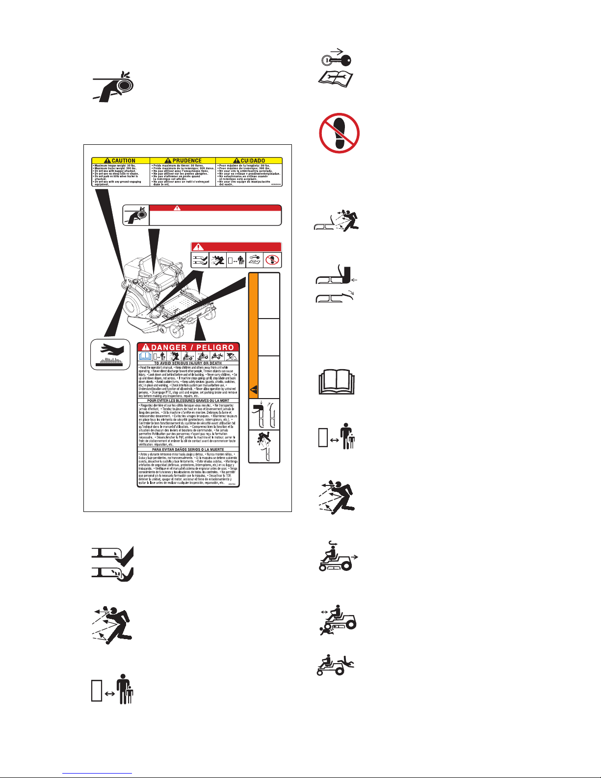
ALWAYS remove key to prevent unauthorized
use.
DO NOT operate at too fast a rate. Slow down
before turning.
Stop engine before removing grass catcher or
unclogging chute.
DO NOT mow on wet grass. Reduced traction
could cause sliding.
DO NOT try to stabilize the machine by putting
your foot on the ground.
Know the weight of loads. Limit loads to those
you can safely control and the unit can safely
handle.
ALWAYS keep protective structures, guards
and panels in good repair, in place and
securely fastened.
Do not operate without either entire grass
catcher or the discharge guard in place.
DO NOT operate in reverse unless absolutely
necessary. ALWAYS look down and behind
before and while backing; especially for
children.
Follow the manufacturer’s recommendations
for wheel weights or counterweights to
improve stability when using attachments.
NEVER carry passengers–especially
children–even with blades off.
Use extra care when approaching blind
corners or objects that may obscure vision of
hidden obstacles and children.
If you cannot back up a slope or you feel
uneasy on it, do not mow it.
Mow up and down slopes, not across them.
Use slow speed on any slope. Tires may lose
traction on slopes even though the brakes are
functioning properly.
Keep all movements on the slope
slow
and
gradual.
DO NOT make sudden changes in
speed or direction.
Use extra care while operating machines with
grass catcher or other attachments. They can
affect stability of the machine.
Avoid starting, stopping, or turning on a slope.
If tires lose traction, disengage the blades and
proceed slowly
straight
down the slope.
DO NOT operate on slopes over 10˚.
DO NOT park on slopes unless necessary. If
unit is parked on a slope, ALWAYS chock or
block wheels and set parking brake.
DO NOT disengage or bypass transmission
and coast downhill.
Tow only with a machine that has a hitch
designed for towing. Do not attach towed
equipment except at the hitch point.
Follow the manufacturer’s recommendations
for weight limits for towed equipment and
towing on slopes.
NEVER allow children or others in or on towed
equipment.
On slopes, the weight of the towed equipment
may cause loss of traction and loss of control.
Travel slowly and allow extra distance to stop.
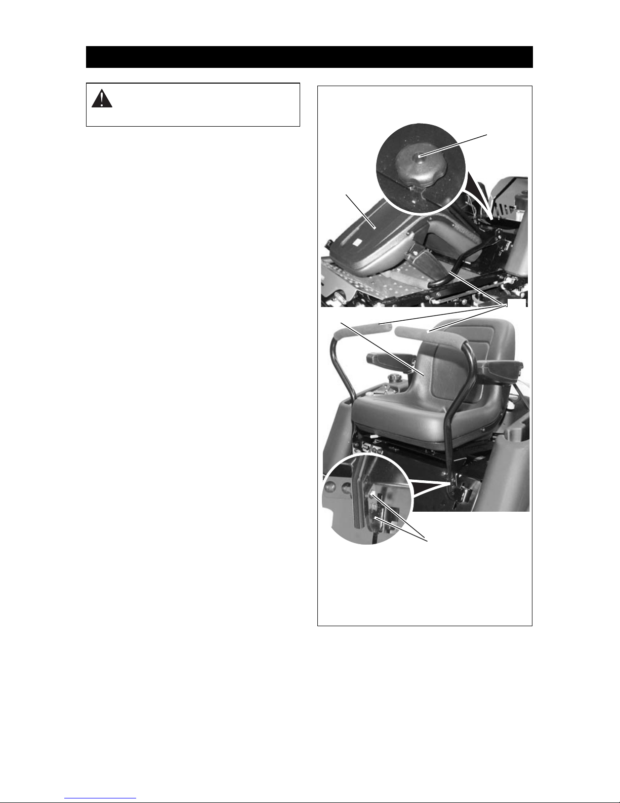
ALWAYS shut off engine, remove key, and
close fuel shut-off valve or drain fuel when
transporting unit on a truck or trailer.
Use extra care when loading or unloading unit
onto trailer or truck.
Secure unit chassis to transport vehicle.
NEVER secure from rods or linkages that
could be damaged.
DO NOT transport machine while engine is
running.
Keep unit free of grass clippings, leaves, and
other debris. Clean up oil or fuel spills.
This product is equipped with an internal
combustion type engine. DO NOT use unit on
or near any unimproved, forest-covered or
brush covered land unless exhaust system is
equipped with a spark arrester meeting
applicable local, state or federal laws. A spark
arrester, if it is used, must be maintained in
effective working order by operator.
Fuel is highly flammable and its vapors are
explosive. Handle with care. Use an approved
fuel container.
NO smoking, NO sparks, NO flames. ALWAYS
allow engine to cool before servicing.
NEVER fill fuel tank when engine is running or
hot from operation.
NEVER fill or drain fuel tank indoors.
NEVER overfill fuel tank.
Replace fuel cap securely and clean up spilled
fuel.
NEVER fill containers inside a vehicle or on a
truck or trailer bed with a plastic liner. Always
place containers on the ground away from
your vehicle before filling.
When practical, remove gas-powered
equipment from the truck or trailer and refuel it
on the ground. If this is not possible, then
refuel such equipment on a trailer with a
portable container, rather than from a gasoline
dispenser nozzle.
Keep the nozzle in contact with the rim of the
fuel tank or container opening at all times until
fueling is complete. Do not use a nozzle lock-
open device.
If fuel is spilled on clothing, change clothing
immediately.
Avoid Electric Shock. Objects contacting both
battery terminals at the same time may result
in injury and unit damage. DO NOT reverse
battery connections.
Explosive Gases from battery can cause
death or serious injury. Poisonous battery fluid
contains sulfuric acid and its contact with skin,
eyes or clothing can cause severe chemical
burns.
NO flames, NO sparks, NO smoking near
battery.
ALWAYS wear safety glasses and protective
gear near battery.