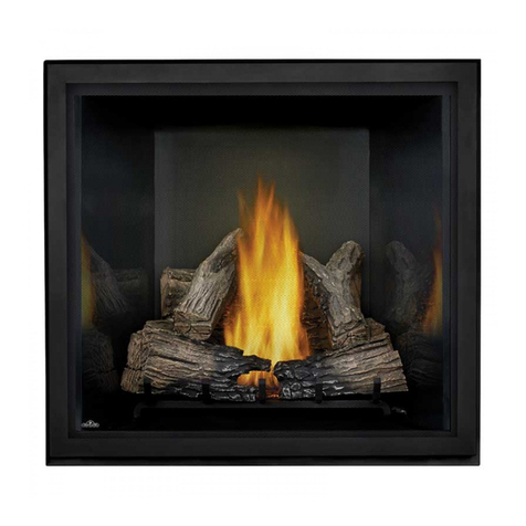
Alpine TR42 - NG TAMARRON User manual

TAMARRON
HEAT RECIRCULATIVE GAS FIREPLACE
MODEL : TR42 – NG Natural Gas
TR42 – LP Propane
INSTALLATION AND SERVICE MUST
BE PERFORMED BY A QUALIFIED
INSTALLER, SERVICE AGENCY OR THE
GAS SUPPLIER.
FOR YOUR SAFETY
Do not store or use gasoline or other
flammable vapors and liquids in the vicinity
of this or any other appliance.
WHAT TO DO IF YOU SMELL GAS:
• Do not try to light any appliance.
• Do not touch any electrical switch; do
not use any phone in your building.
• Immediately call your gas supplier from
a neighbor’s phone. Follow the gas
supplier’s instructions
• If you cannot reach your gas supplier,
call the fire department.
WARNING: If the information in these
instructions are not followed exactly, a fire or
explosion may result causing property
damage , personal injury or loss of life.
Improper installation, adjustment, alteration,
service or maintenance can cause property
damage, personal injury or loss of life.
INSTALLER:
PLEASE LEAVE THIS MANUAL WITH THE CUSTOMER
HOMEOWNER:
PLEASE KEEP THESE INSTRUCTIONS FOR FUTURE REFERENCE
These gas appliances have been tested in accordance
with National Safety Standards, and have been certified
by Intertek for installation & operation as described in
these Installation and Operating Instructions in the
United States.
Check with your local building code agency before you
begin your installation to ensure compliance with local
codes, including the need for “permits” and follow-up
inspections. If any problems are encountered regarding
code approvals, or if you need clarification of any of the
instructions contained here, contact:
ALPINE GAS FIREPLACES
#801-768-8411 / www.alpinegasfireplaces.com
INSTALLATION AND OPERATING INSTRUCTIONS
Alpine Gas Fireplaces
782 West State Street
Lehi, Utah 84043 Tested by:
7/04

2 Alpine TR42 Direct Vent Gas Fireplace

3
Alpine TR42 Direct Vent Gas Fireplace
TABLE OF CONTENTS
OPERATING INSTRUCTIONS
Aeration Adjustment……………24/25
Remote Control/Thermostat……….25
Operation Instruction Plate...............26
First Fire ...........................................27
Lighting Procedure...........................27
Shutdown Procedure.........................27
FIREPLACE MAINTENANCE
Maintenance Instructions ...............27
Cleaning the Glass............................27
Cleaning the Logs.............................27
Cleaning the Valve Chamber............27
Cleaning Gold /Brass Trims.............27
SERVICE
Log Replacement..............................28
Inspecting the Pilot...........................28
Removing/Installing the Valve.........29
Replacement Parts List..................... 30
TROUBLESHOOTING GUIDE
Gas Control System ......................... 31
WARRANTY
Warranty……………………………32
GENERAL INFORMATION
Rating Plate........................................ 4
Before Starting....................................5
General Safety Information ................5
System Specifications.........................6
Derating the Burner ............................6
INSTALLATION REQUIREMENTS
Locating the Fireplace........................6
Gas Line Installation...........................7
Clearances...........................................7
Mantel Clearances..............................7
Hearth Materials.................................7
Framing and Finishing........................8
VENTING
Venting Planning................................9
Venting Components List...................9
Vent Termination Clearances...........10
Horizontal /Vertical Components.....11
Horizontal Venting Installation........12
Vertical Venting .........................12/13
Horizontal Venting ………….…14-16
Horizontal Installation………….17/18
Vertical Installation…………….18/19
Flex Venting……………………….20
WIRING
Blower Wiring.............................21/22
Millivolt System...............................22
LOG AND EMBER INSTALLATION
Log/Ember Placement………………22/23
GLASS AND LOUVER INSTALLATION
Glass Trim Installation…..………...24
Louver Installation………………...24

4 Alpine TR42 Direct Vent Gas Fireplace
GENERALINFORMATION
Listed: DIRECT VENT GAS FIREPLACE HEATER
Tested to: ANSI Z21.88a-2003/CSA2.33a-2003
VENTED GAS FIREPLACE HEATER.
Report No. 3060953 (Jun.04)
DO NOT REMOVE THIS LABEL
Serial Number: TAMARRON TR42-
PROPANE : TAMARRON TR42-LP
Minimum supply pressure 11” WC
Manifold pressure high 10.0” WC
Manifold pressure low 6.4” WC
Orifice Size # 50 DMS
Minimum input 31,000 BTU/h
Maximum input 38,000 BTU/h
Altitude 2500 – 6500 Ft
NATURAL GAS :TAMARRON TR42-NG
Minimum supply pressure 4.5” WC
Manifold pressure high 3.5” WC
Manifold pressure low 2.2” WC
Orifice Size # 32 DMS
Minimum input 32,000 BTU/h
Maximum input 41,500 BTU/h
Altitude 2500 – 6500 Ft
Model TR42-LP
Model TR42-NG
Use Only Simpson Dura-Vent GS System . Use only Simpson vent cap #0991 on vertical applications. This appliance must be installed in accordance
with the manufacturer’s installation instructions and with local codes, if any; if not, follow the current ANSI Z223.1 in the USA.
This vented gas fireplace heater is not for use with air filters. Electrical supply 120VAC, 3.5 Amps, 60Hz.
This appliance is only for use with the type of gas indicated on the rating plate and may be installed in an aftermarket, permanently located
manufactured home (USA only) or mobile home, where not prohibited by local codes. See owner’s manual for details. This appliance is not convertible
for use with other gases, unless a certified kit is used. This appliance approved for bedroom installations.
VENTED GAS FIREPLACE HEATER NOT FOR USE WITH SOLID FUEL.
Alpine Gas Fireplaces
Lehi, Utah
Made in USA
Field Converted
Put Label Here
This appliance must be installed in
accordance with the following
minimum clearances:
2” to combustibles – Top
1/2” to combustibles – Sides
1” to combustibles – Back
0” to combustibles – Bottom
22” from top of stove – Ceiling
28” from top of stove-Ceiling (flex)
6” to combustible Mantel projecting 6”
from wall. Add 1” of height for every 1”
of projection after the 6” minimum.
Flue clearances are as follows:
Horizontal Pipe
2” to combustibles – Top
1” to combustibles – Sides
1/2” to combustibles – Bottom
1 1/2” Clearance to Vertical Pipe
This appliance may be recessed until
the front of the unit is flush with any
combustible facing material. Non
combustibles may overlap.

5
Alpine TR42 Direct Vent Gas Fireplace
GENERALINFORMATION
IMPORTANT:
SAVE THESE INSTRUCTIONS
The TR-36 Direct Vent Fireplace must be installed in
accordance with these instructions. Carefully read all
the instructions in this manual first. Consult the
“authority having jurisdiction” to determine the need
for a permit prior to starting the installation. It is the
responsibility of the installer to ensure this fireplace is
installed in compliance with the manufacturer’s
instructions and all applicable codes.
BEFORE YOU START
Safe installation and operation of this appliance
requires common sense, however, we are required by
ANSI Standards to make you aware of the following:
INSTALLATION AND REPAIR SHOULD BE
DONE BY A QUALIFIED SERVICE PERSON.
THE APPLIANCE SHOULD BE INSPECTED
BEFORE USE AND AT LEAST ANNUALLY BY
A PROFESSIONAL SERVICE PERSON. MORE
FREQUENT CLEANING MAY BE REQUIRED
DUE TO EXCESSIVE LINT FROM
CARPETING, BEDDING MATERIAL, ETC. IT
IS IMPERATIVE THAT CONTROL
COMPARTMENTS, BURNERS AND
CIRCULATING AIR PASSAGEWAYS OF THE
APPLIANCE BE KEPT CLEAN.
DUE TO HIGH TEMPERATURES, THE
APPLIANCE SHOULD BE LOCATED OUT OF
TRAFFIC AND AWAY FROM FURNITURE
AND DRAPERIES.
WARNING: FAILURE TO INSTALL THIS
APPLIANCE CORRECTLY WILL VOID YOUR
WARRANTY AND MAY CAUSE A SERIOUS
HOUSE FIRE.
CHILDREN AND ADULTS SHOULD BE
ALERTED TO THE HAZARDS OF HIGH
SURFACE TEMPERATURES, ESPECIALLY
THE FIREPLACE GLASS, AND SHOULD STAY
AWAY TO AVOID BURNS OR CLOTHING
IGNITION.
YOUNG CHILDREN SHOULD BE
CAREFULLY SUPERVISED WHEN THEY ARE
IN THE SAME ROOM AS THE APPLIANCE.
CLOTHING OR OTHER FLAMMABLE
MATERIAL SHOULD NOT BE PLACED ON
OR NEAR THE APPLIANCE.
GENERAL SAFETY INFORMATION
1) The appliance installation must conform with
local codes or, in the absence of local codes, with
the current National Fuel Gas Code, ANSI
Z223.1 installation code.
2) The appliance when installed, must be electrically
grounded in accordance with local codes, or in
the absence of local codes with the current
National Electrical Code, ANSI/NFPA 70.
3) This appliance must be connected to the specified
vent and termination cap to the outside of the
building envelope. Never vent to another room or
inside a building. Make sure that the vent is fitted
as per venting instructions.
4) Inspect the venting system annually for blockage
and any signs of deterioration.
5) Venting terminals shall not be recessed into a
wall or siding.
6) Any safety glass removed for servicing must be
replaced prior to operating the appliance.
7) To prevent injury, do not allow anyone who is
unfamiliar with the operation to use the fireplace.
8) Wear gloves and safety glasses for protection
while doing required maintenance.
9) Be aware of electrical wiring in locations in walls
and ceilings when cutting holes for termination.
10) Under no circumstances should this appliance be
modified. Parts that have been removed for
servicing should be replaced prior to operating
this appliance.
11) Installation and any repairs to this appliance
should be done by a qualified service person. A
professional service person should be called to
inspect this appliance annually. Make it a practice
to have all of your gas appliances checked
annually.
12) Under no circumstances should any solid fuels
(wood, paper, cardboard, coal etc.) be used in this
appliance.
13) The appliance area must be kept clear and free of
combustible materials, gasoline and other
flammable vapors and liquids.
14) If the pilot goes out for any reason, turn the
control knob to the off position. Wait five
minutes before attempting to re-light pilot.
15) Never obstruct the flow of ventilation and
combustion air to the fireplace.

6 Alpine TR42 Direct Vent Gas Fireplace
SYSTEM SPECIFICATIONS
Burner Inlet Orifice Sizes:
(2500 TO 6500 feet altitude )
Natural Gas: #40 Propane: #52
Max. Input Rating – Natural Gas 41,500 Btu/h
Propane 38,000 Btu/h
Min. Input Rating – Natural Gas 32,000 Btu/h
Propane 31,000 Btu/h
Min. Supply Pressure Natural Gas 4.5” w.c.
Propane 11.0” w.c.
Max. Supply Pressure Natural Gas 8.0” w.c.
Propane 13.0” w.c.
Manifold Pressure
Natural Gas 3.5” +/-0.2” w.c.
Propane 10” +/-0.2” w.c.
Minimum Gas Line Pipe Size: 1/2”
Electrical: 120 V.A.C. System
Amperage Rating: .62 Amps
Optional Fan Kit : #431-917
Venting: Simpson Duravent Direct Vent (4” x 6 5/8”)
Must use high wind termination on vertical
applications (Simpson part # 0991)
GENRAL INFORMATION/INSTALLATION REQUIREMENTS
LOCATING THE FIREPLACE
1) When selecting a location for your Gas Fireplace,
ensure that the clearances outlined in this manual are
adhered to strictly.
2) The fireplace must be installed on a flat, solid,
continuous surface. If the appliance is to be raised
off the floor on a platform, it must be securely
fastened to a sturdily constructed platform.
3) If the appliance is to be installed on carpeting,
combustible vinyl tiling, or any other combustible
surface other than wood flooring, a wood panel or
metal panel must be installed on top of the existing
flooring. The panel must extend the full width and
depth of appliance.
4) The Alpine TR42 fireplace can be installed into
many different applications. See Figure 1 for
examples.
5) Lay out fireplace dimensions on installation site
before proceeding with installation. This will ensure
proper clearances and assist in identifying potential
problems before installation.
6) Make sure to review the vent termination before
proceeding.
Fig. 1 – Installation Placement Options
DERATING THE BURNER
The fireplace has been designed to operate at elevations up
to 4500 ft. above sea level. The fireplace will need to be
derated at elevations above 6500 ft. The orifice will need to
be reduced one number drill size.
This appliance may be installed in an aftermarket, perma-
nently located, manufactured home (USA only) or mobile
home, where not prohibited by local codes.
This appliance is only for use with the type of gas indicated
on the rating plate. This appliance is not convertible with
other gases, unless a certified kit is used.

7
Alpine TR42 Direct Vent Gas Fireplace
INSTALLATION REQUIREMENTS
GAS LINE INSTALLATION
IMPORTANT: Gas piping should be installed only by
trained and qualified technicians.
The appliance and its individual shut-off valve must be
disconnected from the gas supply piping system during any
pressure testing of that system in excess of 1/2” psi.
The appliance must be isolated from the gas supply piping
system by closing its individual shutoff valve during any
pressure testing of the gas supply piping system at test pressures
equal to or less than 1/2” psi.
The gas line can be brought through the left side of the
appliance. The 1/2” service gas line must connect to the
flexible appliance connector which is attached to the main
control valve. DO NOT MAKE THIS CONNECTION
UNTIL ALL PRESSURE TESTING OF THE GAS
PIPING SYSTEM IS COMPLETE. FAILURE TO
DO SO WILL RESULT IN DAMAGE TO THE
MAIN CONTROL VALVE.
Gas piping must conform to the current National Fuel Gas
Code, ANSI Z223.1.
Always consult with the local code official for additional local
codes applicable in your area.
IMPORTANT: Always check for gas leaks with a soap
and water solution or gas leak detector. Never use open
flame for leak testing.
NOTE: To properly check gas pressure, both inlet and
manifold pressures should be checked using the valve
pressure ports on the control valve.
CLEARANCES
IMPORTANT: Clearances listed in this manual must
be adhered to strictly. Failure to maintain these listed
clearances of the fireplace and venting system can re-
sult in a house fire.
Clearance to Combustibles from:
Fireplace Spacers 0”
Fireplace Floor 0”
Ceiling 18”
Ceiling (Flex Vent) 24”
Side Mantel Leg 6”
Mantel Clearance:6” minimum height for a 6”
projection. Add 1” of height for each additional
1” of projection.
Horizontal Vent Pipe
Top of Pipe 2”
Sides of Pipe 1”
Bottom of Pipe 1/2”
Vertical Vent Pipe 1 1/2”
Fig. 2 – Clearance to an adjacent wall
Fig. 3 – Mantel Clearances
HEARTH MATERIALS
A Hearth is not mandatory with the TR 36 fireplace, but
is recommended for aesthetics and for added safety .
Non-combustible materials such as Tile, Brick, Rock, and
Slate are recommended.
In constructing a hearth, hearth material thickness must
be taken into consideration. Avoid using any material that
will block the front of the valve access door at the bottom
of the appliance.
Fig. 4 – Hearth Clearances
NOTE: If the appliance is to be installed on carpeting,
vinyl tiling, or any other combustible material other
than wood flooring, the appliance must be installed on
a metal or wood panel extending the full width and
depth of the appliance.
024681012
0
2
4
6
8
10
12
14
16
side view of
fireplace
4"
mantel
8" mantel
12" mantel sheetrock
4"
8"
12"
top of
fireplace

8 Alpine TR42 Direct Vent Gas Fireplace
INSTALLATION REQUIREMENTS
FRAMING
1) A rough framed opening of 42 1/2” wide by 38” high will
be required for installation. The minimum depth is 21”.
( see figure 5 )
Fig. 5 – Framed Opening
Fig. 6– Corner Installation
5) When sheetrock is applied around the
fireplace a 1/2” gap must be maintained
between the fireplace face and the sheetrock
or any other combustible material. Non-
combustibles such as brick, tile or stone may
butt up to or even overlap the face of the
fireplace. NOTE: If overlapping the face of
the fireplace make sure not to overlap into
the glass frame area. (see figure 8)
2) If the fireplace is to be installed into an
exterior wall, the enclosure or fireplace
chase should be insulated to the same de-
gree as the home to prevent cold air infil-
tration through the fireplace chassis.
Check with your local building official for
any additional local requirements( e.g. vapor
barriers, drywall). Never insulate the fire-
place itself.
NAILING TABS MUST BE BENT
OUT BEFORE FIREPLACE IS
INSERTED INTO FRAMING
THERE ARE FOUR NAILING TABS
3) The fireplace is equipped with four nailing
tabs, which must be bent out before
inserting into the framed opening.
4) Center the fireplace in the framing and
anchor the fireplace, using the nailing
strips provided, to the framing.
(see figure 7)
Fig. 7 – Securing The Fireplace
tile or other non
combustible facing may
be placed against the
fireplace or even
overlap the fireplace
face.
sheetrock and other
combustibles may be
brought to within 1/2"
of the fireplace face
but may not overlap or
even contact the
fireplace.
Fig. 8 – Facing Clearances
70"
50"
Note: header is turned on its
side to maintain clearance
to the vent pipe
42.5"
width
38"
height

9
Alpine TR42 Direct Vent Gas Fireplace
VENTING
Figure 9 – Clearance to Venting
VENTING PLANNING
The Alpine TR-36 uses Simpson Duravent Co Axial
venting systems. The inner tube vents products of
combustion away from the appliance, while the outer tube
draws outside air into the combustion chamber. This is a
closed system and uses no air from the interior of the home
for combustion.
Never attach this fireplace vent to another vent serving
another appliance. Each direct vent gas appliance must use
its own separate venting system. Common venting systems
are prohibited for use with this appliance.
Always vent the fireplace to outside of the building. Never
vent into a garage or enclosed area.
This venting system, in combination with the Alpine TR-
36 Direct Vent Gas Fireplace, has been tested and listed as
a direct vent heater by Intertek. The location of the
termination cap must conform to the requirement in the
Vent Termination Clearances diagram on page 10 of this
manual.
Before proceeding with installation, carefully examine the
chart on page 10 of this manual for options regarding
proper placement of the vent termination.
In all cases, adequate combustion and ventilation air must
be available for the fireplace. Never block the termina-
tion cap. Make sure foliage does not grow around the
termination cap. In all cases, follow the clearances listed
on page 8 of this manual.
NOTE: Never connect this gas appliance to a chimney
flue serving a separate solid-fuel burning appliance.
CLEARANCE
FROM
VERTICAL
PIPE TO
COMBUSTIBLES
IS 1-1/2"
CLEARANCE TO
COMBUSTIBLES ON
HORIZONTAL PIPE IS
2" FROM TOP
1 " FROM SIDES
1/2" BOTTOM
SIMPSON DURAVENT
VENTING COMPONENTS LIST
(4”x6 5/8”)
Stock # Description
46DVA-E45 45 Degree Elbow
46DVA-E90 90 Degree Elbow
46DVA-SC Storm Collar
46DVA-F6 Standard Flashing 0/12 – 5/12
46DVA-F12 Steep Flashing 6/12 – 12/12
46DVA-WS Wall Strap
09183 Firestop Spacer
46DVA-16A 16” Extension
46DVA-8A 8” Extension
09382 17” - 24” Adjustable pipe
46DVA-12 12” pipe
46DVA-24 24” pipe
46DVA-36 36” pipe
46DVA-48 48” pipe
46DVA-VCH Vertical Termination Cap
46DVA-HC Horizontal Termination Cap
46DVA-DC Wall Thimble
46DVA-SNK14 14” Snorkel Termination Cap
46DVA-SNK36 36” Snorkel Termination Cap
09361 Vinyl Siding stand-off
Parts not supplied by Simpson
09362 Flue Adapter
09364 Vent Guard
09367 Horizontal Firestop
09301 Attic Insulation Shield

10 Alpine TR42 Direct Vent Gas Fireplace
VENTING
VENT TERMINATION CLEARANCES
A= Clearance above grade, veranda, porch, deck, or balcony (min. 12”)
B= Clearance to window or door that may be opened (12”)
C= Clearance to permanently closed window (12”)
(recommended to prevent condensation on window)
D= Vertical clearance to ventilated soffit located above the terminal
within a horizontal distance of (24”) from the centerline of the
terminal (min. 18”)
E= Clearance to unventilated soffit (min. 15”)
F= Clearance to outside corner (19”)
G= Clearance to inside corner (12”)
H= Not to be installed above a meter / regulator assembly within (3’)
M= Clearance above paved sidewalk or a paved driveway located on
public property (min. 84”)
N= Clearance under a veranda, porch, deck, or balcony (min. 12”)
P= Clearance to obstructions in front of the termination such as bushes,
fences, sheds, decks, other structures is (24”)
Note:
- A vent shall not terminate directly above a sidewalk
or paved driveway which is located between two single
family dwellings and serves both dwellings.
- Only permitted if veranda, porch, deck, or balcony is
fully open on a minimum of two sides beneath the floor.
Vertical
Termination
24"
D
E
V
PV
M
B
F
V
V
V
V
V
V
V
V
G
A
Inside
corner detail
Vertical
Termination
24"
18"
H
L
N
A
J
B
B
B
B
A
K
Openable
A
Openable
B
C
Fixed
Closed
A
A
ir supply outlet
VVent terminal
A
rea where terminal is not permitted
MatthewHobby is thec oolest!

11
Alpine TR42 Direct Vent Gas Fireplace
VENTING
SIMPSON DURAVENT VENTING
Horizontal or Vertical Terminations
The Simpson Dura Vent System offers a complete line of component parts for both horizontal and vertical installations.
Read installation instructions included within the termination cap box.
The following is a list of components required for a basic
horizontal termination installation.
1 Horizontal Termination Cap
1 90 Degree Elbow
1 Flue Adapter (installed on unit from factory)
1 Horizontal Firestop
1 12” Pipe
1 17” -24” Adjustable Pipe
If vinyl is to be used, a vinyl siding standoff should also
be used. If brick or rock is to be applied to the exterior of
the home, make sure that the cap is extended to the
thickness of the brick or rock. The Terminal must never
be recessed into the wall. A brick standoff is available
for this application.
The following is a list of components required for a basic
vertical termination installation.
1 Vertical Termination Cap
1 Storm Collar
1 Roof Flashing *
2 36” vent pipe
1 Flue Adapter (installed on unit from factory)
* If the home has a chase projecting above the roof line, a
roof flashing will not be needed.
The vertical termination should project above the finished
chase a minimum of 10”. See local codes for other vent-
ing requirements in your area.

12 Alpine TR42 Direct Vent Gas Fireplace
Vertical Venting
Maximum Vertical Height 37 FT.
Minimum Vertical Height 4 FT.
Up to eight (8) 45 Degree elbows may be used
NOTE: A vent restrictor must be installed in the
fireplace if the vertical height is more than 12 feet.
Only Simpson Duravent GS Piping (4” x 6 5/8”)
May be Used on This Appliance.
Piping Clearances
Vertical Pipe
1 1/2” to Combustibles
Horizontal Pipe
2” To Combustibles—Top
1” To Combustibles—Sides
1/2” To Combustibles—Bottom
VENTING

13
Alpine TR42 Direct Vent Gas Fireplace
Venting With Four (4) 90 Degree Elbows
V(min) H(max) V1 (min) H1 (max) V2 (min)
1 FT 3 FT 5 FT 3 FT 3 FT
2 FT 5 FT 5 FT 5 FT 3 FT
3 FT 10 FT 5 FT 10 FT 3 FT
NOTE: Horizontal Piping Must Maintain a 1/4” Rise Per Foot.
Piping Clearances
Vertical Pipe
1 1/2” to Combustibles
Horizontal Pipe
2” To Combustibles—Top
1” To Combustibles—Sides
1/2” To Combustibles—Bottom
VENTING

14 Alpine TR42 Direct Vent Gas Fireplace
Horizontal Venting With One 90 Degree Elbow
Vertical Horizontal
1 FT 3 FT
2 FT 8 FT
3 FT 16 FT
NOTE: Horizontal piping must maintain a 1/4” rise per foot .
Piping Clearances
Vertical Pipe
1 1/2” to Combustibles
Horizontal Pipe
2” To Combustibles—Top
1” To Combustibles—Sides
1/2” To Combustibles—Bottom
VENTING

15
Alpine TR42 Direct Vent Gas Fireplace
Note: V1 must be at least a 1 foot length.
Piping Clearances
Vertical Pipe
1 1/2” to Combustibles
Horizontal Pipe
2” To Combustibles—Top
1” To Combustibles—Sides
1/2” To Combustibles—Bottom
Horizontal Venting With Three (3) 90 Degree
Elbows
V(min) H(max) H + H1 (max)
1 FT 3 FT 6 FT
2 FT 4 FT 8 FT
3 FT 6 FT 12 FT
4 FT 8 FT 16 FT
5 FT 16 FT 16 FT
NOTE: Horizontal Piping Must Maintain A 1/4” Rise Per
Foot.
VENTING

16 Alpine TR42 Direct Vent Gas Fireplace
Piping Clearances
Vertical Pipe
1 1/2” to Combustibles
Horizontal Pipe
2” To Combustibles—Top
1” To Combustibles—Sides
1/2” To Combustibles—Bottom
Horizontal Venting With Two (2) 90 Degree Elbows
V (min) H+ H1 (max)
3 FT 8 FT
4 FT 10 FT
5 FT 12 FT
NOTE: Horizontal Piping Must Maintain A 1/4” Rise Per Foot.
VENTING

17
Alpine TR42 Direct Vent Gas Fireplace
VENTING
VENTING – HORIZONTAL
Install the vent system according to the instructions
included in the venting kit received with the fireplace.
1. With the unit in the desired location, check to determine
if wall studs or roof rafters will obstruct the venting system
when attached. If this is the case, you may want to adjust
the location of the unit or consult with your framing
contractor for options in adjusting the framing.
2. Determine where the horizontal vent pipe will exit
through the exterior wall. Frame a 10” x 10” opening at the
exit location and mount the horizontal firestop. This
firestop will assure that all clearances to the vent pipe are
maintained . (See fig. 10)
3. To properly assemble the Simpson Vent pipe a high
heat sealant , such as Mil-Pac or Dap High Heat Mortar,
should be used to ensure an airtight vent. Apply the sealant
to the inner collar of the pipe, line up the lugs on the out-
side of the pipe, slip the pipe together and then twist the
pipe to lock the lugs together (see fig 11). Wrap the outer
seam of the vent pipe with aluminum tape or seal with sili-
con.
Fig. 11 – Applying Sealant
NOTE: Clearances to combustibles from the vent pipe
must be adhered to. See the table below for proper
clearances.
Horizontal Venting Clearances
TOP OF PIPE 2” to combustibles
SIDES OF PIPE 1” to combustibles
BOTTOM OF PIPE 1/2” to combustibles
4. Install the vertical pipe needed, followed by the elbow to
achieve the pre-determined exit height and then extend the
horizontal section of vent through the pre-mounted
horizontal firestop. The pipe extending through the
exterior wall should not extend beyond the surface, which
the termination cap will be mounted to, more than 1” but
needs to be at least flush with this surface ( see fig. 12).
5. Carefully slide the vent termination over the vent pipe
from the outside and flush it up against the exterior wall.
Level the termination cap for appearance sake, making sure
the arrow is pointing upward on the termination cap (see
fig. 13). Carefully fasten the termination cap to the exterior
wall (see fig. 14) using the screws provided in the
termination box. You may seal around the termination cap
with a quality silicone for insulation purposes.
NOTE: All pipe joints must be sealed with Mill-pac or
Dap High Heat Mortar on the inner pipe and aluminum
tape or Silicone on the outer joint.
Mill-pac
Sealant
Silicone Sealant
Fig. 10 – Horizontal Firestop

18 Alpine TR42 Direct Vent Gas Fireplace
VENTING
Fig. 13– Termination Orientation
HOT
Wall Penetration
Heat Shield
Make Sure Arrow
is pointing up.
Fig. 12– Pipe Through Wall
Fig.14– Anchoring Termination to Wall
VERTICAL TERMINATION
1. Maintain the 1-1/2” clearances to combustibles
when passing through ceilings, walls, roofs, enclosures,
attic rafters, or other nearby combustible surfaces. See the
diagrams on page 13 of this manual for the maximum
vertical rise of the venting and the maximum horizontal
offset limitations.
2. With the gas appliance in its desired location,
drop a plumb bob from the ceiling to the position of the
appliance flue exit and mark the location where the vent
will penetrate the ceiling. Drill a small hole at this point.
Next, drop a plumb bob from the roof to the hole
previously drilled in the ceiling and mark the spot where
the vent will penetrate the roof. Determine if ceiling joists,
roof rafters, or other framing will obstruct the venting
system. You may choose to relocate the fireplace or offset
the venting to avoid cutting framing members (see figure
16).
Firestop
Flashing
Fig. 15– Vertical Venting
3. A Firestop spacer must be installed in the floor or ceiling
of every level. To install the Firestop spacer in a flat ceiling
or wall, cut a 10 inch square hole. Frame the hole as
shown in (Figure 17) and install the firestop.
4. Assemble the desired lengths of pipe and elbows. Ensure
that all pipes and elbow connections are in the fully twist–
locked position and sealed with Mill-pac brand sealant on
the inside collar and aluminum tape on the exterior. An air
tight seal must be created.
FIRESTOP

19
Alpine TR42 Direct Vent Gas Fireplace
45 degree
Elbow
W all Strap
Plumbers Tape
Firestop
Fig. 16– Venting Offsets
Firestop
Spacer
Framing
10" x 10" Square
Hole
Fig. 17 – Firestop Installation
5. Cut a hole in the roof centered on the small drilled hole
placed in the roof in Step 2. The hole should be of
sufficient size to meet the minimum requirements for
clearance to combustibles of 1 1/2”.
6. Continue to complete the assembly of the pipe lengths.
See (figure 18) for proper vent height projecting through
the roof.
7. Ensure that the vent is vertical and secure the base of the
flashing with roofing nails. Slide the storm collar over the
pipe section and seal with a mastic type sealant.
8. Install the vent cap by twist locking it in place.
See Offset Table for additional details (fig. 19). Fig. 18 – Vent Height Table
Roof Pitch Minimum Vent Height
Above Roof Line
Flat to 9/12 2’
9/12 to 10/12 2-1/2’
10/12 to 11/12 3-1/4’
11/12 to 12/12 4’
12/12 to 14/12 5’
14/12 to 16/12 6’
16/12 to 18/12 7’
Vent Height
Fig.19 – Offset Table
Offset Pipe Length (L) Height
4-3/4” 0” 13-1/4”
9” 6” 17-1/2”
11-1/4” 9” 19-1/2”
L
Height
Offset
NOTE: If the pipe is to pass through any closets or
storage spaces, the vent must be enclosed. The vent
must never be allowed to come in contact with
combustibles
VENTING

20 Alpine TR42 Direct Vent Gas Fireplace
INCORRECT CORRECT
24"
2"
12"
Flex vent may be used in a number of basic installations to simplify the
installation process. It must be noted that the use of flex vent increases
the height of the ceiling (as shown in the illustration below right) by
6”. It also needs to be noted that all firestopping practices must be
adhered to with flex venting also.
It is recommended that a high temperature sealant such as Mill Pac or Dap
High Heat Mortar be used to seal the center flex liner to the appliance
vent nipple as well as the vent nipple on the termination cap. Aluminum
tape or silicone is recommended to seal the outer flex liner to the appli-
ance and to the vent termination. All four points of connection should be
fastened with a band clamp.
As noted in the venting chart below, there must be a minimum of 1’ of
vertical rise before the transition into the horizontal run. 1’ of vertical
rise will provide a maximum of 2’ horizontal run, which will accomplish
most exterior wall applications. 2’ of vertical rise will accommodate up to
3’ of horizontal run, which is the maximum horizontal run allowable with
flex vent. Only one 90° transition may be used with the flex vent taking it
from the vertical to the horizontal. Offsetting in the horizontal plane is not
allowed.
INSTALLING FLEX VENT
Horizontal Venting With One 90 Degree Elbow
Vertical Horizontal
1 FT 2 FT
2 FT 3 FT
3-8 FT 3 FT
NOTE: Horizontal piping must maintain 1/4” rise per foot.
Piping Clearances
Vertical Pipe
1 1/2” to Combustibles
Horizontal Pipe
2” To Combustibles—Top
1” To Combustibles—Sides
There are spacers Provided to maintain the orientation between the
two liners. The spacers need to be utilized at the beginning and the
end of a 90° transition and also at 12” intervals during the horizontal
run of the flex vent. ( see below)
The maximum horizontal run may be 3’ with a minimum vertical rise of
3’ as shown in the chart below. A maximum vertical run of 8’ may be
utilized. If your vertical run is greater than 3’ you may incorporate up to
two bends into the vertical run. The bends must not exceed 45°.
VENTING
This manual suits for next models
1
Table of contents