Amane Studio Kirapika Solar Cooker Series User manual

- 1 -
The Karupika Solar Cooker
from the Kirapika Solar Cooker Series
Do-It-Yourself Manual V3-I
Model: IP8E / F
Amane Studio
○ ○ ○ Contents ○ ○ ○
1. Checking the Parts ・・・・・・・・・・・・・・・ 2
2. Assembling the Outer(circumferential) Frame ・・・・・ 5
3. Assembling the Core Bar Assy. ・・・・・・・・ ・ ・ 5
4. Assembling the Mirror ・・・・・・・・・・・・・・ 9
5. Assembling the Parabola ・・・・・・・・・・・・・11
6. Mounting the Core Bar Assy.・・・・・・・・・・・ 14
7. Assembling the Pan・・・・・・・・・・・・・・・・16
8. Adjusting the Angle of the Trivet ・・・・・・・・・・17
Thank you very much for purchasing the Karupika solar cooker.
*Please read carefully this do-it-yourself manual, and assemble the kit properly.
*Please have this manual in your careful keeping and provide for a rainy day.
*Please refer to the User Manual for handling the solar cooker.
We humbly ask you to understand that the do-it-yourself kit is not covered by our
one-year warrant.
All manuals and user guides at all-guides.com
all-guides.com

- 2 -
1. Checking the Parts
Please check all the parts and their required quantities you have in the package.
○
1Core Bar: 1 pc. Knob Bolt C: 1 pc. ○
26 Core Bar Extension ○
2: 1 pc.
○
39 wing nuts: 2 pcs.
○
52 Spring Washers: 2 pcs.
○
53 Bar End Washer: 1 pc.
○
3Center Mirror Assy.: 1 pc.
○
26 Knob Bolt C: 1 pc.○
41 Long Bolt M4*30 mm: 1 pc.
○
4a Holder A: 1 pc. ○
4b Holder B: 1 pc. A sticker attached
○
5a KARU Flanges: 7 pcs. ○
5b Top KARU Flange: 1 pc.
○
9a Pan Frame: 1 pc.
○
6KARU mirrors (A)
: 12 pcs.
○
9b Concave Pan Frame : 1 pc.
○
11 Trivet Rod E: 1 pc.
○
7a KARU mirror (Ba)
: 1 pc.
○
10 Bushes: 2 pcs. ○
32 Rubber Tubes: 3 pcs.
○
7b KARU mirror (Bb)
○
12 Trivet Rods F: 2 pcs. : 1 pc.
With a large hole
○
8KARU mirror (C)
: 1 pc.
13a Summer Angle Setter: 1 pc. 13b Winter Angle Setter: 1 pc.
All manuals and user guides at all-guides.com

- 3 -
○
18 Leg No. 1: 1 pc. Numbers punched.
○
19 Leg No. 2: 1 pc. ○
25 Sighting Device Assy.: 1 set
○
20 Leg No. 3: 1 pc.
○
30 Knob Bolt D: 1 pc. ○
29 Finger Nut K: 1 pc.
○
24 Adjusting Bolt A: 1 set
○
17 Tripod Post: 1 pc.
Hexagon-head Bolts M4*18 mm with cross recess (silvery): 2 pcs. ○
27
Tapping Screws 4*8: 2 pcs. ○
28
○
16 Spacer Sleeve: 1 pc.
○
14 Parabola Cover: 1 pc. ○
36 Flange Nuts (large): 4 pcs.
Both made of cardboard
○
15 Handgrip: 1 pc.
○
51 Grease: 1 pack
○
21 Center Mirror Box: 1 pc. ○
22 Column-base for assembling work: 1 pc.
○
52 Body of the Pan: 1 pc. (20 cm for the Emodel, and 18 cm for the Fmodel)
○
54 Grip of the Pan: 1 pc. ㊵O-ring Pack
○
53 Glass Cover: 1 pc.
㊳Instant adhesive
○
55 Grip-fixing Bolt: 1 pc.
【Documents 】
・User Manual……………………..……… 1 copy
(with the Diagrams for the Timing of the Solar Cooker Rearrangements)
・Do-it-yourself Manual …………………1 copy
All manuals and user guides at all-guides.com

- 4 -
*Screws and nuts are supplied in somewhat extra quantities.
Keeping them in monkey dishes helps your works go well.
*Your needful tools;
A Scotch tape,scissors, Phillips screwdriver, and cutter-knife.
NOTE! The driver bit should be a Phillips #2, and a heavy-duty grip required.
✔
*An electric driver helps your works go quite quick. △
✔
NOTE! Avoid a windy place for your works.
-- - Clip and paste the following labels on screw and nut bags, and have smooth jobs - --
○
33 50 pcs. ○
42 24 pcs.
Flange Nuts Machine Screws M3 * 6 mm
(small, sunny yellow) (sunny yellow)
○
34 4 pcs. ○
44 2 pcs.
Machine Screws Hexagon-head Bolts
M4 * 8 mm(silver) M6 * 25 mm (silver)
○
35 Tooth-picks ○
45 12 pcs.
Machine Screws
5 pcs. M4 * 12 mm
(sunny yellow)
○
36 2 pcs. ○
46 17 pcs.
Flange Nuts Flange Nuts
(large, sunny yellow) (medium, sunny yellow)
○
37 16 pcs. ○
47 10 pcs.
Machine Screws Machine Screws
M3 * 8 mm M3 * 6 mm
(sunny yellow) (stainless steel)
All manuals and user guides at all-guides.com

- 5 -
2. Assembling the Outer Frame
1. Mount the Handgrip ○
15 on KARU Flange Top ○
5b . Check the facing.
Fig. 1 ○
36
Close-up
○
36 Fig. 2
The Summer Angle Setter 13a can be used as a wrench.
Fig. 3
NOTE!
○
15 An excessive torque deforms
the setter metal. Fig. 4
True up the surfaces of handgrip-ends and nuts flat.
2. Put together, by hand-start, KARU Flanges ○
5a and ○
5b to make a circular form.
(See Figs. 5 and 6). Fit the bosses into holes at their overlapping areas, and hand-tack
them with the Screws ○
45 and Nuts ○
46 .
3. Tighten fully all the Screws ○
45 on the circular Flange.
NOTE! Loose tightening causes the outer frame deformed into an ellipsoidal shape under
the influence of the external pressure. All the Screws ○
45 must be tighten firmly.
○
46 The hole for a boss to fit. ○
46
Overlap the ends and hand-start screws.
○
5a ○
5a The boss ○
5a
○
45 Fig. 6 Fig. 5
○
45
○
5b Finished shape of the outer frame.
The Handgrip ○
15 comes to the top of the completed solar cooker.
3. Assembling the Core Bar Assy.
1. Mount the Trivet Rods F ○
12 on the Pan Frames ○
9a and ○
9b , and tighten them with two
flat surfaces of the Nuts ○
36 . ○
36
○
9b ○
36 90°
○
9b
○
36 ○
12 ○
36 ○
12
Fig. 7 ○
9a Fig. 8
True up the screwed Trivet Rod end and the nut surface flat.
All manuals and user guides at all-guides.com

- 6 -
2. Screw the Trivet Rod E ○
11 , with the Nut ○
36 on its screwed part, into a screwed hole
on the Core Bar ○
1.○
44
○
44 ○
9a Prior to Step 3.2 the Nut ○
36 is mounted
on the screwed part of the Trivet Rod E ○
11 .
○
1Close up
Fig. 9 ○
36 Fig. 10
True up the male screw end and the bar surface flat.
3. Mount the Pan Frame ○
9a on the Core Bar ○
1with two Bolts ○
44 .
4. Mount the Pan Frame ○
9b on the Core Bar ○
1and tighten bolts with two Nuts ○
36 .
On this area, do not give an excessive torque.
Hold this part to tighten the screw. A jog between surfaces does not matter.
○
9b ○
36
13a ○
36
○
2○
1
○
2○
1
Fig. 11 Fig. 12
5. Screw fully the end of the Core Bar Extension ○
2into a hole at the Core Bar ○
1end.
NOTE! As loosening of the link between two bars during usage makes the parabola
unstable, tighten the extension firmly.
At this assembly stage, please choose one of the three
different positions depending on the solar altitude.
Position A Position B Position C
90 ° 82° 72°
45 ° 31° 24°
Fig. 13 Fig. 14 Fig.15
For high solar altitudes For medium solar altitudes For low solar altitudes
1. Check the latitude of the area where you plan to use the solar cooker.
2. Check the Diagrams for the Timing of the Solar Cooker Rearrangements at the end of the
All manuals and user guides at all-guides.com
all-guides.com

- 7 -
User Manual. Select the set of circle charts applicable to the latitude of your area, and then
select “a.” or “b.” shown below.
a. I will rearrange the solar cooker to the appropriate position for each season, because I
want to be able to use the solar cooker all the time, all year round.
b. I will choose the position that enables me to use the solar cooker for the longest period of
time in the year without rearranging it because it’s a lot of work. (In this case, please note
that there will be some minutes of the day when you cannot align the solar cooker with the
sun at certain periods of the year.)
If you chose “a.” above, use the position applicable to each season
shown in the large circle chart.
Fig. 16 shows example of areas with latitudes between 25°and
27.5° N (in decimal degrees).
■The period of use: May 1 to Aug. 10 à Position A
■Aug. 11 to Sep. 10 and Apr. 1 to Apr. 30 à Position B
■Sep. 11 to Mar. 31 à Position C
Fig. 16 If you chose “b.” above, use the position shown in
the small circle chart at the top right of the large circle chart.
In this example, ■the suitable position is Position B.
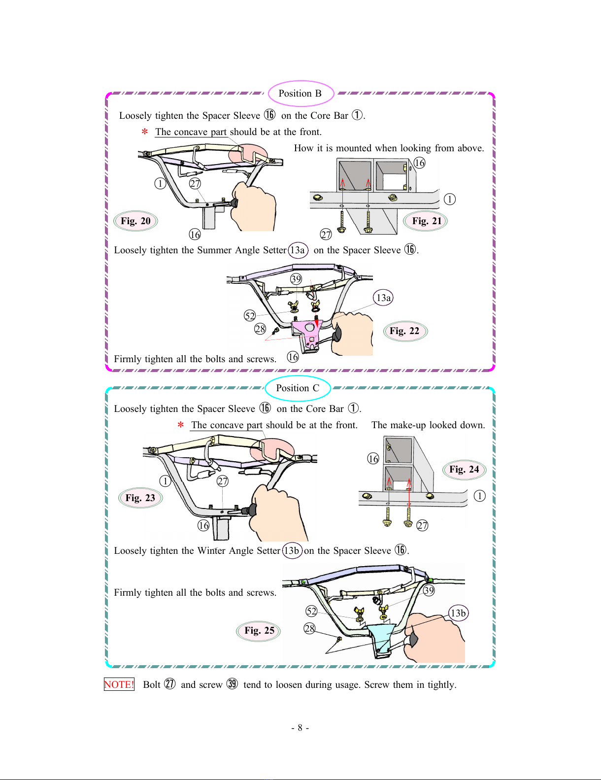
Position A
Loosely tighten the Spacer Sleeve ⑯on the Core Bar ①.
*The concave part comes at the back.
How it is mounted when looking from above.
○
16
○
1Fig. 17 ○
1
○
27 ○
16 ○
27 Fig. 18
Loosely tighten the Summer Angle Setter 13a
on the Spacer Sleeve ⑯.
Firmly tighten all the bolts and screws. ○
39
○
52
13a ○
16 Fig. 19
○
28
All manuals and user guides at all-guides.com

- 8 -
Position B
Loosely tighten the Spacer Sleeve ⑯on the Core Bar ①.
*The concave part should be at the front.
How it is mounted when looking from above.
○
16
○
1○
27
○
1
Fig. 20 Fig. 21
○
16 ○
27
Loosely tighten the Summer Angle Setter 13a on the Spacer Sleeve ⑯.
○
39
13a
○
52
○
28 Fig. 22
Firmly tighten all the bolts and screws. ○
16
Position C
Loosely tighten the Spacer Sleeve ⑯on the Core Bar ①.
*The concave part should be at the front. The make-up looked down.
○
16
Fig. 24
○
1○
27
Fig. 23 ○
1
○
16 ○
27
Loosely tighten the Winter Angle Setter 13b on the Spacer Sleeve ⑯.
Firmly tighten all the bolts and screws. ○
39
○
52 13b
Fig. 25 ○
28
NOTE! Bolt ㉗and screw ㊴tend to loosen during usage. Screw them in tightly.
All manuals and user guides at all-guides.com

- 9 -
4. Assembling the Mirror
1. Bent two ears on each of the KARU Mirrors ⑥,⑦and ⑧on the right lines
marked with notches at a 45-degree angle. See Fig. 27
It is highly recommended to bend them against a hard edge of a table or anything else to
achieve sharp lines. A round edge is NOT desired. Get straight sharp bent-lines.
NOTE! Incorrect bent-lines result in undesired finish.
NOTE! Be aware of a slight difference between locations of notches on both sides.
Bent-lines
Notches Notches
Fig. 26
Mirror surface Fig. 27
(with a film)
Bent it at a sharp straight line.
Approx. 45°
Cut off a piece
about 3 cm wide.
MIRROR SURFACE (with a film).
Bend it AGAINST Still keep the film on to protect the surface.
Mirror surface.
⑥,⑦and ⑧
Fig. 28
Approx. 45°
2. Before starting next step, please look at the rear face of the Center Mirror Assy. ○
3.
IMPORTANT NOTE! Please do not pull out black screws on four hookups of the
metal band as shown with *marks on Fig. 29, or the Center Mirror Assy. loses
its shape, and it is difficult to regain it.
All manuals and user guides at all-guides.com

- 10 -
Rear face of the Center Mirror Assy. ○
3
(Aluminum basis metal surface)
press fitting nut
Metal band
*Hookup Fig. 29
*Hookup
3. Lay down the Center Mirror Assy. ○
3on soft cloth (the Parabola Cover may be used),
and loosen the screw as shown on Fig. 30.
If the Center Mirror Assy. is set on a cloth-covered bucket, rather than a cloth-covered
flat surface, you can make the assy. more stable during your works.
NOTE! Be careful not to spoil screw heads with the driver tip, or the scratches on the
heads cause poor results of mopping the mirror surface, with fine and nasty fibers
pulled out of a rag and left on screw heads.
NOTE! Excessive pressure on the nut on metal band makes it drop off to the under
side. Be careful not to press the screw head too strongly with the driver tip.
Loosen this screw at first.
Fig. 30 ⑧⑥○
7a
⑥ ⑥*
⑥
*⑥Insert the parts behind.
⑥
Mirror surface ⑥
○
7b
*⑥
⑥
⑥
*⑥○
3The Center Mirror Assy.
⑧
*Hookups ⑥
4. Insert Mirror parts ○
7a between metal bands and the rear surface of
the Center Mirror Assy. ○
3.
All manuals and user guides at all-guides.com

- 11 -
Toothpick ○
35 Metal band
Using a Toothpick ○
35 makes it easy
to ply the band from the Center Mirror
to make a space where a Mirror ○
7a
is inserted.
Fig. 31
5. Fix the Mirror ○
7a with the screw once Rear face
loosen as shown in Step 4.3 and two sets of Machine Screws ○
47 and Flange Nuts ○
33 .
6. Loose all the rest of screws on the rim, and making spaces with the Toothpick ○
35 ,
insert and fix “loosely” all the rest of KARU Mirrors ⑥,⑦and ⑧. The arrangement
is shown in Fig. 30.
7. Check all the Mirror parts are;
“Radially and properly arranged around the middle of the Center Mirror ○
3” and
“All the way seated in”. Mirror surface
Then, fully tighten all the screws.
Fig. 32
A sticker on the rear surface
Finished shape
NOTE! The Mirror is very FRAGILE at this stage. Be careful in handling.
8. Check again all the KARU Mirror parts ⑥,⑦and Fig. 33
⑧are arranged in right locations.
An error in assembling causes ill effects afterwards.
9. Remove all the protective films from
KARU Mirror parts ⑥,⑦and ⑧.
5. Assembling the Parabola.
1. Cut off four side-boards of the Center Mirror Container ○
21 , and cut the basal plate
along the black lines.
A pedestal
Bent side-board-cuttings
○
21 and make triangles.
Fig. 35
Fig. 34 Fix triangles with Scotch tape.
2. Bent side-board-cuttings at two lines as shown in Fig. 35 to make four triangle-shaped
“Pedestals”.
All manuals and user guides at all-guides.com
all-guides.com

- 12 -
Fig. 36
3. Put Scotch tape over cut lines of the
Column-base for assembling work ○
22 .
4. Place the inter-crossed plates, prepared in Step 5.1,
into a column to make a regular octagon.
Fig. 38
×✔
Fig. 37 Column ○
22
5. Place a cloth (the Parabola Cover) over the column to protect
the mirror surface.
The mirror on the right side
overlaps the left one. Hold the rubber-edged mouth softly.
Fig. 39
○
7b
○
37
The column top is covered. Triangle pedestals --- 4 pcs.
Outer frame
(○
14 )
○
22
○
33
Bosses come up-side.
Important NOTE! The label with a Karupika mark must come onto the Handgrip ○
15 .
All manuals and user guides at all-guides.com

- 13 -
6. Put four triangle pedestals around the Column ○
22 .
7. Put the Frame on four Pedestals.
NOTE! The workshop should be large enough for you to move around the Parabola,
rather than moving it around.
If such a place is not available, and if you must Fig. 40
move the Parabola around, you have better to
attach four Pedestals to the bottom of the Outer
Frame with Scotch tape beforehand.
8. Place the preliminarily assembled Mirror on the Frame.
9. Tighten loosely the Mirror to the Frame in 16 places with Screws ○
37 and Nuts ○
33 .
The right one overlapping
In order to prevent the mirror assy. warping upward, ○
37
fix it temporarily on the outer frame with two ○
37 Fig. 41
tooth-picks inserted into the holes on both of holes
next to the one to be screwed. At this time, check
the overlapping parts of the mirrors as shown in Fig.41.○
35 Tooth-picks
10. Tighten LOOSELY all of 16 Screws ○
37 on entire circumference.
11. Cut off the column vertically, and divide it in half horizontally along the
black line.Then, connect sections of two halves to make one large column.
○
22
Fig. 42 Fig. 43 Fig. 44 Make a large column.
12. Place the cover over the large column, and put the Parabola
on it with the mirror surface upward. Fig. 45
13. Insert Screws ○
42 to screw-holes on inner two circles of the
Mirror, and loosely fix them with nuts ○
33 . See Fig. 48.
○
14
Ten screws at the lower part MUST be the Stainless-steel
Screws ○
47 instead of Screws ○
42 to avoid erosion caused by
spills and splashes of boiling liquid. See Fig. 48.
Circuits ○
1○
2
14. Check the entire mirror carefully to see if there is any
bending or warping of the surface. ○
4○
3
The nice secret for this step to be done well is to
tighten screws in the numerical order of the circuits Fig.46
All manuals and user guides at all-guides.com

- 14 -
○
1,○
2,○
3and ○
4, driving a warp of the mirrors to the outer areas. When still a
warp remains, loose some of nearby screws for adjustments, and tighten them fully again.
NOTE! Any of Incorrect bent-lines, mentioned as a NOTE! in Step 4.1 (Page 9), makes
it impossible to avoid warping. In that case, you must adjust incorrect lines.
6. Mounting the Core Bar Assy. Fig. 47
All of four clicks of the Bush ○
10 must hold the hole-edge.
1. Place one of the Bushes ○
10 on the hole in the
KARU Mirror ○
8at the ○
4a side. ○
4a side
See Figs. 47 and 48.
2. Insert the end of the Core Bar Assy. into the hole edged with the bush on the mirror
surface.
At first, insert the end with a washer deep into the hole on the parabola, and then move
the assy. horizontally to insert the end of ○
2into another hole on the opposite side
Clicks of the Bush ○
10 face outside. (Both of the Position A and B.)
*The concave Bar comes front.
○
2
Position B / C
!DO NOT hit the Mirror surface!
○
10
○
7b ○
4a side
○
4b
side ⑧
⑧*The oval hole comes near.
○
47
○
42
Screws inside the dotted lines must
be stainless steel made ones ○
47 .
○
2
○
33 *The concave Bar comes front.
○
10 Position A
Fig. 48 The Angle Setter faces the direction opposite
to that of the Position B and C
NOTE! Be careful not to hit the Mirror surface with the Spacer Sleeve ○
16 ,
when inserting it.
All manuals and user guides at all-guides.com

- 15 -
3. Set the Bush ○
10 at the ○
4a side into the hole on the Mirror ○
8surface.
4. Remove the “washer tightening Screw” from the end of the Core Bar Assy.
Fig. 49 ○
10 ○
35
○
4b
side
⑧ ⑧
Grease
○
51
Fig. 50
5. Using a toothpick, grease slightly the washer on the end of the Core Bar Assy. at the
○
4b
side to prevent frictions. ○
45
6. Now, the Holder B ○
4b is to be mounted on the Parabola. ○
46
7. Grease slightly around the hole on the inner
side of the Holder A ○
4a .○
35 ○
26 ○
4b
Fig. 51 ○
46
Fig. 52 ○
34
○
51
○
4a side upward
8. Replacing the Parabola inclined make the ○
4a
side upward helps to make your job easy. ○
4b
side downward
9. Apply instant adhesive ㊳into the square
hollow in the Bar-end Washer ○
53 before Fig. 53
fitting it to the end of the Core Bar Extension ②.
Insert Screws ○
45 to the holes of the Outer Frame.
㊳
○
2
○
53 Fig. 55
Fig. 54
NOTE! Be careful not to let the Washer ○
53 drop off during the work.
All manuals and user guides at all-guides.com

- 16 -
10. Set Holder A ○
4a with two Flange Nuts ○
46 loosely tighten.
Fig. 56
11. Tighten the Bar with Knob Bolt C ○
26 .
At this job, check the square hollow of the Bar-end Washer ○
26
correctly covering the end of the Core Bar Extension ○
2.Fig, 57
○
2○
53 Fig. 58
✔×
Crisscross-error
NOTE! Ignoring such a crisscross-error and tightening the Knob Bolt C ○
26 may cause
the deformation of the Core Bar Extension ○
2end.
12. After tightening the Screw ○
34 , fully tighten the Screws ○
45 .
13. Mount the Sighting Devise ○
25 inside the Parabola.
Fig. 59
○
46
Fig. 60
○
46 ○
34
○
25 ○
26
○
46
○
34
7. Assembling the Pan
1. Mount the Grip on the Pan. The thumb bent
The hook-hole comes upward. comes upward.
Fig. 61 ○
52 Pan
Grip-fixing Bolt ○
55 Grip ○
54
All the assembling works now have been completed.
All manuals and user guides at all-guides.com
all-guides.com

- 17 -
** Now, you start the next stage, the adjustment of the
main body. Please refer to the “User Manual”. **
8. Adjusting the Trivet
1. Assemble the equipment, following instructions in the “User Manual”.
Your solar cooker assembled from the kit, as it stands, does not hold the pan in a perfectly
horizontal position due to the following defects;
A. Looseness in the structure, and
B. Fudge factors in parts production and assembling.
In this step, such defects are to be corrected.
A. Correcting the tilt caused by looseness in the structure.
Due to a play between the Tripod Post and the Spacer Sleeve, the Trivet is slightly
leaning forward.
Hold the Pot Frame with your both hands, and give it a twist to adjust the tilt.
See Fig. 62.
When the Core Bar Assy. is in the Position B or Position C ,
see Figs 62,63 and 64.
Tighten Finger Nut K ○
29 slightly. ○
16 Spacer Sleeve
Fig. 62 Fig. 64
Close up.
Tripod Post ○
17 A tilt caused by a play.
Fig. 63
In the case of the Position A , twist the assy.
counter-clockwise to correct a tilt as shown in Fig. 65.
Fig. 65
B. Correcting fudge factors in parts production and assembling.
Adjust the pan holding points of three trivet rods by bending them softly and gently with
your fingers to make the position of the pod horizontal. When the rubber tubes of trivet
rods hold the pan at three points at the periphery of its bottom, and pot is kept horizontal,
you get the best result.
All manuals and user guides at all-guides.com

- 18 -
3 points support at the bottom periphery.
Fig. 66 Fig. 67
⑫ ⑪
Rod-ends hang slightly from the bottom.
Manufacturer-and-Seller Information
Amane Studio
1138-1, Shionada, Saku City, Nagano, 384-2102, Japan
Phone: +81 267 51 5430 (Japanese only) Fax: +81 267 51 5431
e-mail info@amane-studio.jp http://amane-studio.jp/
All manuals and user guides at all-guides.com
This manual suits for next models
3
Table of contents