Ametek AMP 200N Instruction Manual

M a n u a l
F o r O p e r a t i o n
AMP 200N
AMP 200N1.1
AMP 200N2
Low frequency signal source for supply
simulation and magnetic fields
The AMP 200N series has been designed as a low-frequency
signal source to generate sinusoidal signals used to simulate
ripple noise and ground shift noise as required by a variety of
standards in the automotive, aircraft and military industry.
The AMP 200N devices is controlled by the EM TEST Autowave
to also allow the generation of non-sinusoidal and customized
signals. Additionally, the AMP 200N series can be used to
generate magnetic fields by means of a radiation loop or small
Helmholtz coils.
•Ford FMC 1278
•Ford EMC-CS-2009
•ISO 11452-8
•ISO 7637-4 (Draft)
•LV 123
•SAE J1113-2
•Daimler Chrysler DC xx
•Fiat 9.90110
•GMW3097
•PSA/Renault EQ/IR 02
•VW TL 82566
•Mercedes MBN 10284-2
•Nissan 28401 NDS 02
•GLoyd GL VI-7-2
Version:
4.0.3 / 23.11.2020
The benchmark for emc
Replaces:
4.0.2 / 18.10.2019
Filename:
UserManual-AMP200N-E-
V4.0.3_reformatted.doc
Printdate:
23.11.20

AMETEK CTS AMP 200N series
Manual for Operation V 4.0.3 3 / 60
Contents
1Safety................................................................................................................................5
1.1 Safety Aspects....................................................................................................................................5
1.2 Safety and warning label on the device..............................................................................................5
1.3 Responsibility of the operator.............................................................................................................6
1.4 General hazard...................................................................................................................................6
1.5 Qualification of personnel...................................................................................................................7
2Standards covered by AMP 200N Series.......................................................................8
2.1 General...............................................................................................................................................8
3Delivery Groups and Put in service...............................................................................9
3.1 Basic equipment AMP 200N Series ...................................................................................................9
3.2 Accessories ......................................................................................................................................10
3.2.1 Frame Bus Termination....................................................................................................................10
3.3 Options .............................................................................................................................................10
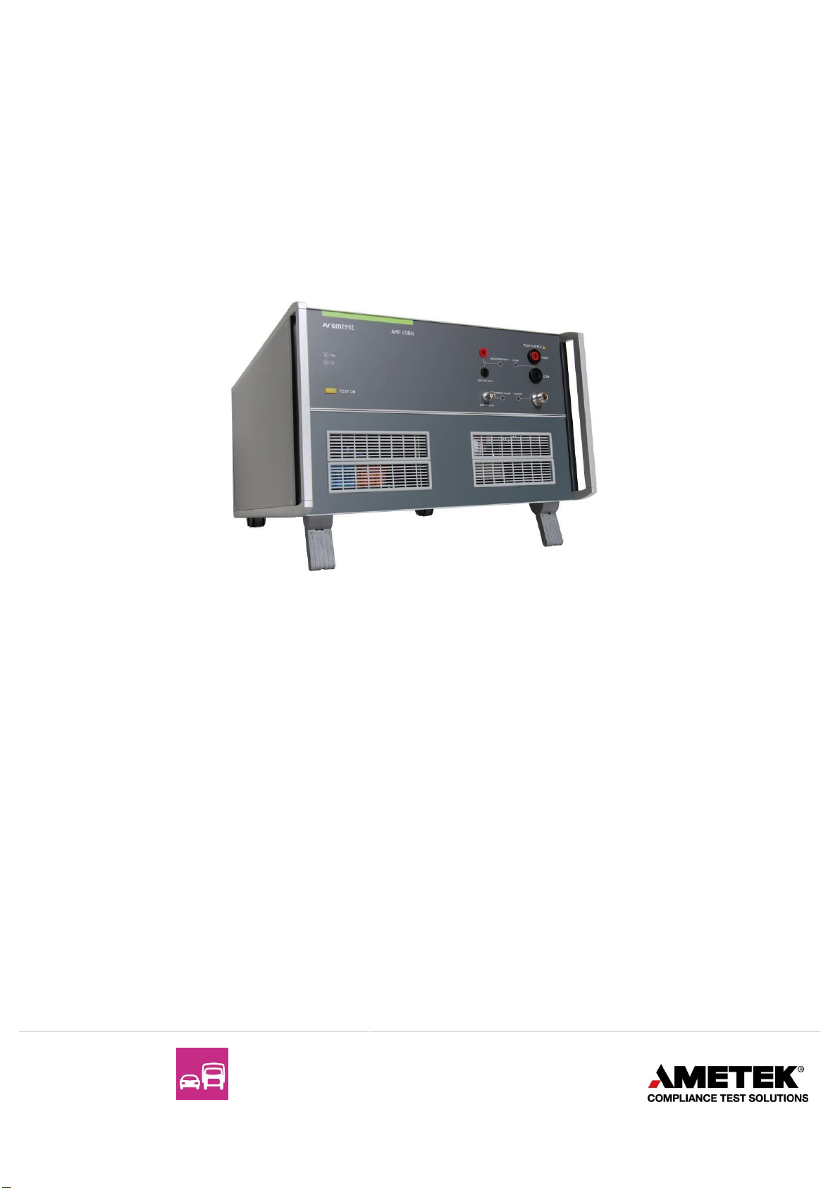
4Operating Functions AMP200N....................................................................................11
4.1 Front view.........................................................................................................................................11
4.2 Rear view..........................................................................................................................................12
5Operating Functions AMP200N1.1 and AMP 200N2...................................................14
5.1 Front view.........................................................................................................................................14
5.2 Rear view..........................................................................................................................................15
6Operation .......................................................................................................................19
6.1 Test Setup with Autowave................................................................................................................19
6.1.1 Cabeling with Autowave ...................................................................................................................19
6.2 Test Setup and cabeling with Netwave and AMP200N Series ........................................................19
6.3 Output Range setting for DC application..........................................................................................20
6.3.1 AMP 200Nx as DC source................................................................................................................20
7Test Equipment AMP 200N...........................................................................................22
7.1 Blockdiagram....................................................................................................................................22
7.2 Construction......................................................................................................................................22
7.3 Cooling..............................................................................................................................................22
7.4 Framebus Interface Module..............................................................................................................23
7.5 Amplifier............................................................................................................................................23
7.6 Measuring Board ..............................................................................................................................23
8Technical data AMP200N..............................................................................................24
8.1 Amplifier output characteristics.........................................................................................................24
8.2 Signal generator output characteristics (built in)..............................................................................24
8.3 Measurements (optional)..................................................................................................................24
8.4 General.............................................................................................................................................24
9Technical data AMP200N1.1.........................................................................................25
9.1 Amplifier output characteristics.........................................................................................................25
9.2 Signal generator output characteristics (built in)..............................................................................25
9.3 Measurements (optional)..................................................................................................................25
9.4 General.............................................................................................................................................25
10 Technical data AMP200N2............................................................................................26
10.1 Amplifier output characteristics.........................................................................................................26
10.2 Signal generator output characteristics (built in)..............................................................................26
10.3 Measurements (optional)..................................................................................................................26
10.4 General.............................................................................................................................................26
11 Maintenance...................................................................................................................28
11.1 General.............................................................................................................................................28
11.2 Calibration and Verification...............................................................................................................28
11.2.1 Factory calibration ............................................................................................................................28
11.2.2 Guideline to determine the calibration period of AMETEK CTS instrumentation.............................28
11.2.3 Calibration of Accessories made by passive components only .......................................................28
11.2.4 Periodically In-house verification......................................................................................................28
12 Application.....................................................................................................................29

AMETEK CTS AMP 200N series
Manual for Operation V 4.0.3 4 / 60
12.1 Using Capacitive loads.....................................................................................................................29
12.2 Power setup AMP 200Nx .................................................................................................................30
12.3 Test setup for AMP 200N Series application....................................................................................30
12.4 Setup for Ford EMC CS 2009-1 .......................................................................................................33
12.4.1 Setup for Magnetic Field Immunity: RI 140 ......................................................................................34
12.4.2 General Information about Magnetic Immunity ................................................................................37
12.4.3 Setup for Coupled Immunity: RI 150 ................................................................................................38
12.4.4 Immunity from Continuous Power Line Disturbances: CI 210..........................................................41
12.4.5 Immunity to Ground Voltage Offset: CI 250 .....................................................................................43
12.5 Immunity to SAE J1113-2.................................................................................................................47
12.6 Immunity to GLoyd GL VI-7-2 –20 (DC).........................................................................................50
11.6.1. DC power supply ..............................................................................................................................50
12.7 Ripple immunity with voltage and current measurement .................................................................52
13 Waveform Verification...................................................................................................55
13.1 RI 140 H-Field verification................................................................................................................55
13.2 CI 250 Pulse verification...................................................................................................................58
14 Appendix........................................................................................................................59
14.1 Declaration of CE-Conformity...........................................................................................................59
14.2 Radiating Loop H-Field versus antenna current...............................................................................60

AMETEK CTS AMP 200N series
Manual for Operation V 4.0.3 5 / 60
1 Safety
1.1 Safety Aspects
Observe all precautions to assure your personal safety. The generators comply with Installation Category II
(excess voltage section).
Pay special attention to safety and operation details!
1.2 Safety and warning label on the device
Please take note of the following explanations of the symbols used in order to achieve the optimum benefit from
this manual and to ensure safety during operation of the equipment.
This symbol warns of a potential risk of shock hazard. The symbol on an instrument
shows that that it can source 1000 volt or more, including the combined effect of
normal and common mode voltages. Use standard safety precautions to avoid
personal contact with these voltages.
This symbol indicates where a caution is required. Refer to the operating instructions
located in the manual in order to protect against personal injury or damage the
equipment.
GROUND Indicates protective Ground Terminal
*CAUTION”
The “CAUTION” symbol indicates a potential hazard. It calls attention to a procedure,
practice or condition which, if not followed, could possibly cause damage to equipment.
Such damage may invalidate the warranty. If a “CAUTION” is indicated, do not proceed
until its conditions are fully understood and met.
“WARNING”
The “WARNING” symbol indicates a potential hazard. It calls attention to a procedure,
practice or condition which, if not followed, could possibly cause bodily injured or
death. If a “WARNING” is indicated, do not proceed until its conditions are fully
understood and met.
Power Supply
If not stated otherwise, the equipment is intended to operate with a power supply not to exceed 250 volts
between phase and neutral or between phase and ground. A proper ground connection through the ground
connector of the power cord is essential for safe operation.
Grounding the Generators
The generators are grounded through the power cord. To avoid electric shock, plug the power cord into a
properly installed receptacle which was tested by a qualified electrician. Have the test performed before
connecting equipment.
Without the protective ground connection, all parts of the generators are potential electric shock hazards. This
may include components which appear to be insulated. The equipment MUST NOT BE USED if this protection is
altered.
Use the Proper Power Cord
Use only power cords and connector specified for your product. Use only power cords in good condition.
Use Proper Fuses
To avoid fire hazard, use only fuses as specified in the parts listing for your product - matching type, voltage and
current rating.
Do Not Remove Covers or Panels

AMETEK CTS AMP 200N series
Manual for Operation V 4.0.3 6 / 60
To avoid personal injury, do not operate the generators without panels and covers.
Do Not Operate in an Explosive Environment
Electric Overload
Never apply power to a connector which is not specified for that particular voltage/current.
1.3 Responsibility of the operator
These operating instructions form an essential part of the equipment and must be available to the operator at all
times. The user must obey all safety instructions and warnings.
WARNING
The purpose of this instrument is the generation of defined interferences signals for EMI
immunity testing. Depending on the arrangement of the test rig, the configuration, the
cabling and the properties of the EUT itself, a significant amount of electromagnetic
radiation may result that could also affect other equipment and systems.
The equipment is designed to operate in industrial environment. For operating in other or
sensitive environment, such as light industry, airport area…, the user may use a shielded
room for operate.
The user himself or herself is ultimately responsible for the correct and controlled operation
of the rig. In case of doubt, the tests should be carried out in a Faraday cage.
1.4 General hazard
Before applying power to the system, verify that your product is configured properly for your application.
WARNING
The generators and their accessories operate at high voltages.
Hazardous voltages may be present when covers are removed. Qualified personnel must
use extreme caution when servicing this equipment.
Circuit boards, test points, and output voltages also may be floating above (below) chassis
ground.
The design of external insulation must be such that it exceeds the maximum voltages of the
device.
WARNING
Risk of electrical shock by touching the output plugs
Only qualified personnel who deal with attendant hazards in impulse generators, are allowed to perform
installation and servicing.
Ensure that the AC power line ground is connected properly to the Power Rack input connector or chassis.
Similarly, other power ground lines including those to application and maintenance equipment must be grounded
properly for both personnel and equipment safety.
Always ensure that facility AC input power is de-energized prior to connecting or disconnecting any cable.
The user must ensure that the output power lines are labeled properly as to the safety hazards and that any
inadvertent contact with hazardous voltages is eliminated.
Guard against risks of electrical shock during open cover checks by not touching any portion of the electrical
circuits. Even when power is off, capacitors may retain an electrical charge. Use safety glasses during open
cover checks to avoid personal injury by any sudden component failure.

AMETEK CTS AMP 200N series
Manual for Operation V 4.0.3 7 / 60
Neither AMETEK CTS GmbH, nor any of the subsidiary sales organizations can accept any responsibility for
personnel, material or inconsequential injury, loss or damage that results from improper use of the equipment
and accessories.
WARNING Personnel fitted with a heart pacemaker must neither operate
the instrument nor approach the test setup while a test is being
executed.
Only approved accessories, connectors, adapters, etc. are to be used to ensure safe operation.
1.5 Qualification of personnel
The generator must be operated only by authorized and trained specialists with detailed knowledge of the
international, national or manufacturer’s test standard.

AMETEK CTS AMP 200N series
Manual for Operation V 4.0.3 8 / 60
2 Standards covered by AMP 200N Series
The AMP 200 is special designed for testing the following standards.
ISO 11452-8
SAE J1113-2
Daimler Chrysler DC 10614-15
Fiat 9.90110 Rev.13 (2007-03)
GMW3097
PSA/Renault EQ/IR 02
VW TL 82566
Mercedes MBN 10284-2
Nissan 28401 NDS 02 Rev.4
GLoyd GL VI-7-2
Automotive
ISO 11452-8
external/internal Magnetic Fields
SAE J1113-2
Voltage Ripple Test, Closed loop / Substitution
Daimler Chrysler DC10614
Magnetic field Rev B
Daimler Chrysler DC11224
Magnetic field
Daimler Chrysler DC10615 Rev D
Supply voltage ripple
Fiat 7_Z0450_2004
Magnetic field
Fiat 9.90110 Rev.13 (2007-03)
Magnetic field
Ford EMC CS 2009 RI140
Coupled Immunity
Ford EMC CS 2009 RI150
Coupled Immunity
Ford EMC CS 2009 CI250
Immunity to Ground Voltage Offset
GMW3097
Magnetic fields
PSA EQ/IR 02
Magnetic fields
Renault EQ/IR 02
Magnetic fields
VW TL 82566
Magnetic fields
MAN M3285
Magnetic fields
Mercedes MBN 10284-2
Magnetic fields
Nissan 28401 NDS 02 Rev.4
Magnetic fields
Volvo STD
Magnetic fields
Other
GLoyd GL VI-7-2
Voltage Ripple test
2.1 General
The AMP 200N series have been designed as a low-frequency signal source to generate sinusoidal signals used
to simulate ripple noise and ground shift noise as required by a variety of standards in the automotive industry
e.g. as per Ford, CI 210 and CI 250 as well as RI 150. The AMP 200N is controlled by the EM TEST Autowave to
also allow the generation of non-sinusoidal and customized signals. Additionally, the AMP 200N can be used to
generate magnetic fields by means of a radiation loop or small Helmholtz coils as per RI 140 of Ford EMC-CS-
2009.1 and Ford FMC 1278.

AMETEK CTS AMP 200N series
Manual for Operation V 4.0.3 9 / 60
3 Delivery Groups and Put in service
Identical accessory parts are delivered only once if several devices are ordered. The delivered packing list is in
each case valid for the delivery.
3.1 Basic equipment AMP 200N Series
•Pulse generator type AMP 200N, AMP 200N1.1 and AMP 200N2
•Power Mains cable Country specific plug
•Control cable (Framebus) SubD 15 pin male / female for AMP200N to (AutoWave or NetWave)
•Signal cable 2 meter BNC cable
•AMP 200N Manual HW manual on USB memory stick, English
•Software Control and Documentation ( AutoWave.control or Netwave.control)
•AW License
•Manual Software manual USB memory stick, English
•Safety manual

AMETEK CTS AMP 200N series
Manual for Operation V 4.0.3 10 / 60
3.2 Accessories
3.2.1 Frame Bus Termination
•Frame Bus terminating for matching the end of the framebus. The
framebus, an internal bus system, is used for control EM Test
devices and work as daisy chain between the equipment. Longer
bus systems must be terminated with a Frame bus termination.
3.3 Options
•Measuring Module
2 Channel Measuring module for frequency selected voltage and current
measuring
•User software " AutoWave.control "
- Test, analysis and documentation with windows
- License version for testing according the most industrial standards
- Report generator with export function to word-processing software
•CN 200N Series
Transformer assembly
•Radiating Loop and Loop Sensor
RL_120: - Radiating loop as per MIL –STD 461-E 120mm, 20 turns
- cable 3m with banana plugs
LS_040: - Loop sensor as per MIL –STD 461-E 40mm, 51 turns
- cable 3m with BNC / speakon plugs
•MN-HField matching resistor
for attenuate the antenna current for reduce the H-field strength.
With the short circuit bridge the user short the internal resistor for full output
current to the Antenna.
Switch position = 1(short circuit) for levels > 1A/m
•C-Box H-Field (AMP 200N2 Only)
For magnetic immunity testing using select Helmholtz coils, an optional C-
Box H-Field is available. This is a capacitor box with selectable capacitance
values used to adjust the resonance point with supported coil can be driven in
resonance to achieve high field strengths. Compatible with HCS_50/28_B
Helmholtz coil for level ISO 11452-8 Level I - IV External and Level I - III
Internal. When this coil is chosen, a dialog to use the C-Box H-Field is
provided. autowave.control will prompt the user to select the appropriate
range on the C-Box.

AMETEK CTS AMP 200N series
Manual for Operation V 4.0.3 11 / 60
4 Operating Functions AMP200N
4.1 Front view
Figure 1
1. TEST ON
2. LED Power
3. LED Fail
4. Measuring input
5. Measuring input enabled
6. 2 wire output indication
7. 2 wire output
8. Coaxial output
9. Coaxial output indication
10. Current clamp input enabled
11. Current clamp input
1 Test ON
Test On button for enable the output of the amplifier. The input signal of the amplifier will be grounded.
The test ON button can be switch on after power up (the power LED is on, no blinking).
2 LED Power
Power On Indication of the present mains power. The illuminated LED shows the power on status.
3 LED Fail
Indication of different Fail status of the AMP 200 as:
Overtemperature, Overload, internal Fail, Safety Circuit
Fail Reset: Press OK in the software Fail window, wait 2 seconds and press AMP200 Test ON button.
4 Measuring Input
Measuring input of the frequency selected voltmeter.
Input range: Max. 200V pk-pk; Frequency range: 10Hz to 250kHz
5 Measuring input indication
LED indication for active measurement.
6 2 wire output indication
LED indication for use the 2-wire output plugs (Flashing).
7 2 wire output
Output 4mm banana plugs for the signal from the amplifier. (The 2-wire and coaxial outputs are always in
parallel).
8 Coaxial output
Output 4N-connector type for the signal from the amplifier. (The 2-wire and coaxial outputs are always in
parallel).
9 Coaxial output indication
LED indication for use the coaxial output. (Flashing).
10 Current clamp input indication
LED indication for the enabled current clamp measurement (Flashing).
11 Current clamp input
BNC input of the frequency selected current clamp measurement.
Input range Max. 10V pk-pk ; Frequency range :10Hz to 250kHz

AMETEK CTS AMP 200N series
Manual for Operation V 4.0.3 12 / 60
4.2 Rear view
ATTENTION
Attention: For cooling the AMP200N a minimum free space at the rear of 20cm is requested
Figure 2
1 Framebus
2 CH 1 IN
3 CH 2 IN
4 Ventilation
5 Safety Circuit
6 Power on switch with fuse
7 Mains selector 115V / 230V
8 Signal OUT
9 Offset OUT
10 Reference Earth connection
1 Frame Bus
Daisy Chain bus with Sub D 15 poles male and female connectors. This port is used as communication and
control bus between EM Test devices. A framebus terminating network is mandatory when the AMP 200Nx
is at the end of the daisy chain.
2 CH 1 IN
BNC input -10V to +10V: This input is used for controlling the VDS 200 or internal amplifier. In switch off
Status the connection is passing to the Signal out output.
3 CH 2 IN
BNC input -10V to +10V to internal amplifier.
4 Ventilation
The cooling output needs at least 20cm space for a free airflow.
5 Safety Circuit
The Safety Circuit is a 12V loop who switches off the power supply of the amplifier. The ac voltage will be
interrupted by a relays.
Attention: After open the Safety circuit there is still same energy in the storage capacitors
of the amplifier.
6 Power on switch with mains fuse
The switch is part of the mains filter. Mains fuses are part of the filter. (230V / 3.15AT and 115V / 6AT).
After switch on the power LED is flashing few seconds, till the AMP200 is ready for use.
7 Mains selector
Selection of 115V / 230V
8 Signal OUT
Control output to system dc source (normally VDS200N). The control signal is generated in the AutoWave or
AMP 200 internal and pass through the AMP200N to the “analog IN” of the VDS200N.
9 Offset OUT
Output control signal from the AMP 200N internal DC source (-10V to +10V).

AMETEK CTS AMP 200N series
Manual for Operation V 4.0.3 13 / 60
10 Reference earth connection
The generator has to be connected to the reference earth plane of the test set up.

AMETEK CTS AMP 200N series
Manual for Operation V 4.0.3 14 / 60
5 Operating Functions AMP200N1.1 and AMP 200N2
5.1 Front view
Figure 3
1. TEST ON
2. LED Power
3. LED Fail
4. Measuring input
5. Measuring input enabled
6. 2 wire output indication
7. 2 wire output
8. Coaxial output
9. Coaxial output indication
10. Current clamp input enabled
11. Current clamp input
1 Test ON
Test On button for enable the output of the amplifier. The input signal of the amplifier will be grounded.
The test ON button can be switch on after power up (the power LED is on, no blinking).
2 LED Power
Power On Indication of the present mains power. The illuminated LED shows the power on status.
3 LED Fail
Indication of different Fail status of the AMP 200N, such as:
Overtemperature, Overload, internal Fail, Safety Circuit
Fail Reset: Press OK in the software Fail window, wait 2 seconds and press AMP200N Test ON button.
4 Measuring Input
Measuring input of the frequency selected voltmeter.
Input range: Max. 200V pk-pk; Frequency range: 10Hz to 250kHz
5 Measuring input indication
LED indication for active measurement.
6 2 wire output indication
LED indication for use the 2-wire output plugs (Flashing).
7 2 wire output
Output 4mm banana plugs for the signal from the amplifier. (The 2-wire and coaxial outputs are always in
parallel).
LED indication for use the coaxial output. (Flashing).

AMETEK CTS AMP 200N series
Manual for Operation V 4.0.3 15 / 60
Figure 4
1. TEST ON
2. LED Power
3. LED Fail
4. Measuring input
5. Measuring input enabled
6. 2 wire output indication
7. 2 wire output
8. Coaxial output
9. Coaxial output indication
10. Current clamp input enabled
11. Current clamp input
8 Coaxial output
Output 4N-connector type for the signal from the amplifier. (The 2-wire and coaxial outputs are always in
parallel).
9 Coaxial output indication
LED indication for use the 2-wire output plugs (Flashing).
10 Current clamp input indication
LED indication for the enabled current clamp measurement (Flashing).
11 Current clamp input
BNC input of the frequency selected current clamp measurement.
Input range Max. 10V pk-pk ; Frequency range :10Hz to 250kHz
5.2 Rear view
ATTENTION
Attention: For cooling the AMP200N a minimum free space at the rear of 20cm is requested

AMETEK CTS AMP 200N series
Manual for Operation V 4.0.3 16 / 60
Figure 5
1 Framebus
2 Reference earth connection
3 Signal OUT
4 CH 1 IN
5 CH 2 IN
6 Offset OUT
7 Ventilation
8 Mains Fuse
9 Safety Circuit
10 Mains input
11 Power on switch
12 Mains selector 115V / 230V
1 Frame Bus
Daisy Chain bus with Sub D 15 poles male and female connectors. This port is used as communication and
control bus between EM Test devices.
2 Reference earth connection
The generator has to be connected to the reference earth plane of the test set up.
3 Signal OUT
Control output to system dc source (normally VDS200N). The control signal is generated in the AutoWave or
AMP 200 internal and pass through the AMP200N to the “analog IN” of the VDS200N.
4 CH 1 IN
BNC input -10V to +10V: This input is used for controlling the VDS 200 or internal amplifier. In switch off
Status the connection is passing to the Signal out output.
5 CH 2 IN
BNC input -10V to +10V to internal amplifier.
6 Offset OUT
Output control signal from the AMP 200N internal DC source (-10V to +10V).
7 Ventilation
The cooling output needs at least 20cm space for a free airflow.

AMETEK CTS AMP 200N series
Manual for Operation V 4.0.3 17 / 60
Figure 6
1 Framebus
2 Reference earth connection
3 Signal OUT
4 CH 1 IN
5 CH 2 IN
6 Offset OUT
7 Ventilation
8 Mains Fuse
9 Safety Circuit
10 Mains input
11 Power on switch
12 Mains selector 115V / 230V
8 Mains Fuse
Mains AMP 200N2 AMP 200N1.1 AMP 200N1
115 V 16 AT 16 AT 2 x 8 AT
230 V 10 AT 10 AT 2 x 4 AT
9 Safety Circuit
The Safety Circuit is a 12V loop who switches off the power supply of the amplifier. The ac voltage will be
interrupted by a relays.
Attention: After open the Safety circuit there is still same energy in the storage capacitors
of the amplifier.
10 Mains Input
115VAC/230VAC 16A input connector (build in socket: IEC-60320 C20, compatible plug: IEC-60320 C19).
11 Mains Switch
After switch on the power LED is flashing few seconds, till the AMP200 is ready for use.
12 Mains selector
Selection of 115V / 230V

AMETEK CTS AMP 200N series
Manual for Operation V 4.0.3 18 / 60
Figure 7
1 Framebus
2 Reference earth connection
3 Signal OUT
4 CH 1 IN
5 CH 2 IN
6 Offset OUT
7 Ventilation
8 Mains Fuse
9 Safety Circuit
10 Mains input
11 Power on switch
12 Mains selector 115V / 230V
See AMP 200N1.1, except SIGNAL OUT. The AMP 200N2: The SIGNAL OUT output is only active when the
AMP is turned on.

AMETEK CTS AMP 200N series
Manual for Operation V 4.0.3 19 / 60
6 Operation
The AMP 200N needs an AutoWave generator or a Netwave for operate. The AutoWave/Netwave generator
controls the AMP 200N via the framebus. The user needs the autowave.control or Netwave.controlsoftware
for operate the system with the AMP200N.
6.1 Test Setup with Autowave
The typical test setup with the control cable connections is illustrate in figure 4.1
For operation with AMP200N the software
AutoWave.control is necessary. For device control the
following interfaces must be used:
Devices GPIB Ethernet
AutoWave AMP200N X X
AutoWave AMP200N VDS200x X
NOTE: If the user has a device which needs GPIB,
(example VDS200x), it is mandatory to use
the GPIB interface.
Figure 8 General Test setup with AMP 200N and AutoWave
6.1.1 Cabeling with Autowave
The general cabling with AMP 200N is
illustrated in Figure 3.2.
There are many applications that use an
AMP200N. Please refer to the setup
description in the specific standards.
Chapter Applications shows a selection test
setup and their specific software settings for
different tests.
List of cable connections:
Computer to…
AutoWave GPIB / IEEE488
Ethernet
AutoWave & VDS200x GPIB / IEEE488
AutoWave to AMP 200N
Framebus OUT Framebus IN Sub-D 15 poles
CH 1 CH 1 IN BNC
CH 2 CH 2 IN BNC
AMP 200N to VDS 200x
Signal OUT 0-10V BNC
AMP 200N
Framebus OUT Termination Sub-D 15 poles
Figure 9 System cabling using AMP 200N
6.2 Test Setup and cabeling with Netwave and AMP200N Series
The typical test setup with the control cable connections is illustrate in figure 4.3

AMETEK CTS AMP 200N series
Manual for Operation V 4.0.3 20 / 60
For operation with AMP200N Series the
software Netwave.control is necessary.
The AMP200N is controlled via the
Framebus interface from the Netwave.
The NetWave is computer controlled via
GPIB or Ethernet interface.
Figure 10 General Test setup with Netwave and AMP 200N/N1
6.3 Output Range setting for DC application
The AMP 200N is a class A amplifier with two output ranges with the following output specifications:
Range max. current
LOW
MED
HIGH
AMP 200N Imax
±35Vp/5.0A
±70Vp/2.5A
AMP 200N1 Imax
±35Vp/16.0A
±70Vp/8.0A
AMP 200N2 Imax
±25Vp/18.0A
±55Vp/14.0A
±80Vp/10.0A
The output Range selection must be made in the Device Setup of the Autowave software.
How to change the Output Range:
1. Select in the Device Setup the
AMP200N
2. Select the AMP200N model
3. Select in the Area Output
Range the correct range.
For the most application the
LOW range with a maximal
current is the best choice.
6.3.1 AMP 200Nx as DC source
It is generally not recommended to use the AMP 200N series as a DC source, but if necessary, it is
recommended to check in advance the equipment maximum current consumption during the test. Then select
the suitable output range for equipment operation. Please take care to the circumstance that the maximum
peak or inrush current must be inside the current specification. Otherwise an alarm will occur and the AMP200N
will stop and prompt an error message.
This manual suits for next models
3
Table of contents
Other Ametek Portable Generator manuals
Popular Portable Generator manuals by other brands

Champion Global Power Equipment
Champion Global Power Equipment 201227 Operator's manual

Honeywell
Honeywell 2000 Watt Operator's manual

Firman
Firman W03381 owner's manual

Hyundai
Hyundai HG2700 Original instructions

Z.I.P.P.ER MASCHINEN
Z.I.P.P.ER MASCHINEN ZI-STE2800IV user manual

DuroStar
DuroStar DS4000S user manual