Arcoaire A Series Guide

N80ESN/N80ESL(Series A): Installation, Start–Up, Operating and Service and Maintenance Instructions
Manufacturer reserves the right to change, at any time, specifications and designs without notice and without obligations.
1
Installation, Start–Up, Operating and
Service and Maintenance Instructions
NOTE: Read the entire instruction manual before starting the
installation.
SAFETY CONSIDERATIONS . . . . . . . . . . . . . . . . . . . . . . . . . . . . . 2
INTRODUCTION . . . . . . . . . . . . . . . . . . . . . . . . . . . . . . . . . . . . . . . 3
CODES AND STANDARDS . . . . . . . . . . . . . . . . . . . . . . . . . . . . 3
ELECTROSTATIC DISCHARGE (ESD) PRECAUTIONS PROCE-
DURE. . . . . . . . . . . . . . . . . . . . . . . . . . . . . . . . . . . . . . . . . . . . . . . 4
LOCATION . . . . . . . . . . . . . . . . . . . . . . . . . . . . . . . . . . . . . . . . . . . . 5
GENERAL . . . . . . . . . . . . . . . . . . . . . . . . . . . . . . . . . . . . . . . . . . . 5
AIR FOR COMBUSTION AND VENTILATION . . . . . . . . . . . . 5
Table 1 – Minimum Free Area Required for Each Combustion Air
Opening or Duct to Outdoors. . . . . . . . . . . . . . . . . . . . . . . . . . . . . 6
Table 2 – Minimum Space Volumes for 100% Combustion, Ventila-
tion, and Dilution from Indoors . . . . . . . . . . . . . . . . . . . . . . . . . . . 7
INSTALLATION . . . . . . . . . . . . . . . . . . . . . . . . . . . . . . . . . . . . . . . . 8
UPFLOW INSTALLATION . . . . . . . . . . . . . . . . . . . . . . . . . . . . . 8
DOWNFLOW INSTALLATION . . . . . . . . . . . . . . . . . . . . . . . . . 8
Table 3 – Opening Dimensions - In. (mm) . . . . . . . . . . . . . . . . . . 9
HORIZONTAL INSTALLATION . . . . . . . . . . . . . . . . . . . . . . . . 9
LOCATION RELATIVE TO COOLING EQUIPMENT . . . . . . 10
AIR DUCTS . . . . . . . . . . . . . . . . . . . . . . . . . . . . . . . . . . . . . . . . . . . 11
GENERAL REQUIREMENTS . . . . . . . . . . . . . . . . . . . . . . . . . . 11
SUPPLY AIR CONNECTIONS . . . . . . . . . . . . . . . . . . . . . . . . . 11
Table 4 – Air Delivery - CFM (With Filter)* . . . . . . . . . . . . . . . 12
Table 5 – Dimensions . . . . . . . . . . . . . . . . . . . . . . . . . . . . . . . . . 14
GAS PIPING. . . . . . . . . . . . . . . . . . . . . . . . . . . . . . . . . . . . . . . . . . . 14
Table 6 – Maximum Capacity of Pipe* . . . . . . . . . . . . . . . . . . . . 15
ELECTRICAL CONNECTIONS. . . . . . . . . . . . . . . . . . . . . . . . . . . 16
Table 7 – Electrical Data . . . . . . . . . . . . . . . . . . . . . . . . . . . . . . . 17
J-BOX RELOCATION . . . . . . . . . . . . . . . . . . . . . . . . . . . . . . . . 18
ACCESSORIES . . . . . . . . . . . . . . . . . . . . . . . . . . . . . . . . . . . . . . 19
NOTES FOR THERMOSTAT WIRING DIAGRAMS . . . . . . . 20
VENTING. . . . . . . . . . . . . . . . . . . . . . . . . . . . . . . . . . . . . . . . . . . . . 20
GENERAL VENTING REQUIREMENTS . . . . . . . . . . . . . . . . 20
Table 8 – Combined Appliance Maximum Input Rating
in Thousands of Btuh per Hour . . . . . . . . . . . . . . . . . . . . . . . . . . 21
Table 9 – Minimum Allowable Input Rating of Space-Heating Appli-
ance in Thousands of Btuh per Hour . . . . . . . . . . . . . . . . . . . . . . 21
EXTERIOR MASONRY CHIMNEY FAN + NAT
INSTALLATIONS WITH TYPE-B DOUBLE-WALL
VENT CONNECTORS ©NFPA & AGA . . . . . . . . . . . . . . . . . . 22
VENTING NOTES FOR Fig. 31 - Fig. 43 . . . . . . . . . . . . . . . . . 25
START-UP, ADJUSTMENT, AND SAFETY CHECK . . . . . . . . . 25
GENERAL. . . . . . . . . . . . . . . . . . . . . . . . . . . . . . . . . . . . . . . . . . 25
Table 10 – Altitude Derate Multiplier for U.S.A. . . . . . . . . . . . . 27
Table 11 – Orifice Size* and Manifold Pressure (In. W.C.) for Gas In-
put Rate . . . . . . . . . . . . . . . . . . . . . . . . . . . . . . . . . . . . . . . . . . . . 28
Table 12 – Orifice Size* And Manifold Pressure (In. W.C.) For Gas
Input Rate. . . . . . . . . . . . . . . . . . . . . . . . . . . . . . . . . . . . . . . . . . . 29
Table 13 – Gas Rate (Cu Ft./Hr.). . . . . . . . . . . . . . . . . . . . . . . . . 29
SERVICE AND MAINTENANCE PROCEDURES. . . . . . . . . . . . 30
GENERAL. . . . . . . . . . . . . . . . . . . . . . . . . . . . . . . . . . . . . . . . . . 31
ELECTRICAL CONTROLS AND WIRING . . . . . . . . . . . . . . . 31
CARE AND MAINTENANCE . . . . . . . . . . . . . . . . . . . . . . . . . . . . 31
CLEANING AND/OR REPLACING AIR FILTER. . . . . . . . . . 32
Table 14 – Filter Size Information (In. / mm) . . . . . . . . . . . . . . . 32
BLOWER MOTOR AND WHEEL. . . . . . . . . . . . . . . . . . . . . . . 32
CLEANING HEAT EXCHANGER . . . . . . . . . . . . . . . . . . . . . . 33
SEQUENCE OF OPERATION . . . . . . . . . . . . . . . . . . . . . . . . . . . . 34
WIRING DIAGRAM . . . . . . . . . . . . . . . . . . . . . . . . . . . . . . . . . . . . 36
TROUBLESHOOTING . . . . . . . . . . . . . . . . . . . . . . . . . . . . . . . . . . 37
PARTS REPLACEMENT INFORMATION GUIDE . . . . . . . . . . . 39
CASING GROUP . . . . . . . . . . . . . . . . . . . . . . . . . . . . . . . . . . . . 39
ELECTRICAL GROUP . . . . . . . . . . . . . . . . . . . . . . . . . . . . . . . 39
BLOWER GROUP . . . . . . . . . . . . . . . . . . . . . . . . . . . . . . . . . . . 39
GAS CONTROL GROUP . . . . . . . . . . . . . . . . . . . . . . . . . . . . . . 39
HEAT EXCHANGER GROUP. . . . . . . . . . . . . . . . . . . . . . . . . . 39
INDUCER GROUP . . . . . . . . . . . . . . . . . . . . . . . . . . . . . . . . . . . 39
Portions of the text and tables are reprinted from current edition of NFPA
54/ANSI Z223.1E, with permission of National Fire Protection Association,
Quincy, MA 02269 and American Gas Association, Washington DC 20001. This
reprinted material is not the complete and official position of the NFPA or ANSI
on the referenced subject, which is represented only by the standard in its entirety.
N80ESN/N80ESL(Series A)
Single Stage, Multi-Speed ECM,
Non–Condensing Gas Furnace
Input Capacities: 45,000 Thru 155,000 Btuh
Use of the AHRI Certified TM Mark indicates a
manufacturer’s participation in the program. For
verification of certification for individual products,
go to www.ahridirectory.org.
D
E
S
I
G
N
C
E
R
T
I
F
I
E
D

N80ESN/N80ESL(Series A): Installation, Start–Up, Operating and Service and Maintenance Instructions
Manufacturer reserves the right to change, at any time, specifications and designs without notice and without obligations.
2
SAFETY CONSIDERATIONS
Improper installation, adjustment, alteration, service, maintenance, or
use can cause explosion, fire, electrical shock, or other conditions which
may cause death, personal injury, or property damage. Consult a
qualified installer, service agency, or your distributor or branch for
information or assistance. The qualified installer or agency must use
factory-authorized kits or accessories when modifying this product.
Refer to the individual instructions packaged with the kits or accessories
when installing.
Follow all safety codes. Wear safety glasses, protective clothing, and
work gloves. Have a fire extinguisher available. Read these instructions
thoroughly and follow all warnings or cautions include in literature and
attached to the unit. Consult local building codes, the current editions of
the current edition of National Fuel Gas Code (NFGC) NFPA 54/ANSI
Z223.1 and the current edition of National Electrical Code (NEC) NFPA
70.
Recognize safety information. This is the safety-alert symbol . When
you see this symbol on the unit and in instructions or manuals, be alert to
the potential for personal injury.
Understand the signal words DANGER, WARNING, and CAUTION.
These words are used with the safety-alert symbol. DANGER identifies
the most serious hazards which will result in severe personal injury or
death. WARNING signifies hazards which could result in personal
injury or death. CAUTION is used to identify unsafe practices which
may result in minor personal injury or product and property damage.
NOTE is used to highlight suggestions which will result in enhanced
installation, reliability, or operation.
The following additional safety considerations should be followed for
gas furnaces:
1. Use only with type of gas approved for this furnace. Refer to the
furnace rating plate.
2. Install this furnace only in a location and position as specified in the
“Location” section of these instructions.
3. Provide adequate combustion and ventilation air to the furnace
space as specified in “Air for Combustion and Ventilation” section.
4. Combustion products must be discharged outdoors. Connect this
furnace to an approved vent system only, as specified in the
“Venting” section of these instructions.
5. Never test for gas leaks with an open flame. Use a commercially
available soap solution made specifically for the detection of leaks
to check all connections, as specified in the “Gas Piping” section.
6. Always install furnace to operate within the furnace’s intended
temperature-rise range with a duct system which has an external
static pressure within the allowable range, as specified in the
“Start-Up, Adjustments, and Safety Check” section. See furnace
rating plate.
7. When a furnace is installed so that supply ducts carry air circulated
by the furnace to areas outside the space containing the furnace, the
return air shall also be handled by duct(s) sealed to the furnace
casing and terminating outside the space containing the furnace.
See “Air Ducts” section.
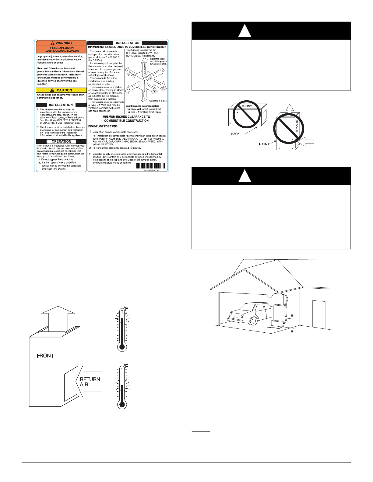
8. A gas-fired furnace for installation in a residential garage must be
installed as specified in the warning box in the “Location” section.
9. The furnace may be used for construction heat provided that the
furnace installation and operation complies with the first
CAUTION in the LOCATION section of these instructions.
10. These Multipoise Gas-Fired Furnaces are CSA (formerly A.G.A.
and C.G.A). design-certified for use with natural and propane gases
(see furnace rating plate) and for installation in alcoves, attics,
basements, closets, utility rooms, crawlspaces, and garages. The
furnace is factory-shipped for use with natural gas. A CSA listed
accessory gas conversion kit is required to convert furnace for use
with propane gas.
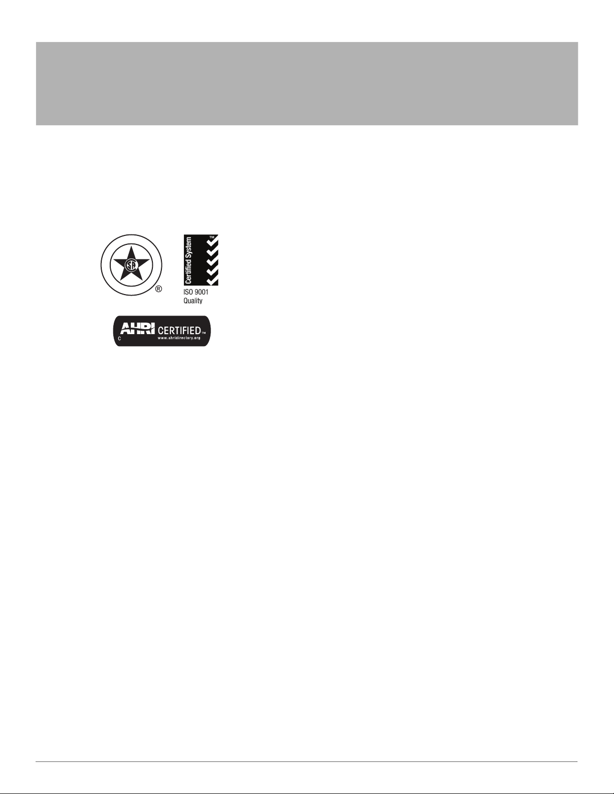
11. See Fig. 1 for required clearances to combustible construction.
12. Maintain a 1-in. (25 mm) clearance from combustible materials to
supply air ductwork for a distance of 36 inches (914 mm)
horizontally from the furnace. See current edition of NFPA 90B or
local code for further requirements.
13. These furnaces SHALL NOT be installed directly on carpeting, tile,
or any other combustible material other than wood flooring. In
downflow installations, factory accessory floor base MUST be used
when installed on combustible materials and wood flooring. Special
base is not required when this furnace is installed on manufacturer’s
coil model numbers END4X, ENW4X or coil casing model number
NAEA is used. See Fig. 1 for clearance to combustible construction
information.
WARNING
!
FIRE, EXPLOSION, ELECTRICAL SHOCK, AND
CARBON MONOXIDE POISONING HAZARD
Failure to follow this warning could result in dangerous operation,
serious injury, death, or property damage.
Improper installation, adjustment, alteration, service, maintenance, or
use could cause carbon monoxide poisoning, explosion, fire, electrical
shock, or other conditions which may cause personal injury or property
damage. Consult a qualified service agency, local gas supplier, or your
distributor or branch for information or assistance. The qualified
service agency must use only factory-authorized and listed kits or
accessories when modifying this product.
WARNING
!
FIRE, EXPLOSION, ELECTRICAL SHOCK, AND
CARBON MONOXIDE POINSING HAZARD
Failure to follow this warning could result in dangerous operation,
personal injury, death, or property damage.
Furnaces shall NOT be twinned (i.e. tandem or staged operation) unless
approved in factory technical specifications literature for the furnace. A
factory authorized, field-supplied Twinning Kit MUST be used.
Consult furnace pre-sale literature for specific models approved for
twinning and the correct twinning kit. Twinned furnaces must be
installed on both a common supply AND a common return duct system
as shown in the Twinning Kit Installation Instructions. Only two
furnaces can be twinned on a common supply and return duct system
using a factory authorized twinning kit.
CAUTION
!
FURNACE RELIABILITY HAZARD
Improper installation or misapplication of furnace may require
excessive servicing or cause premature component failure.
Application of this furnace should be indoors with special attention
given to vent sizing and material, gas input rate, air temperature rise,
unit leveling, and unit sizing.
CAUTION
!
CUT HAZARD
Failure to follow this caution may result in personal injury.
Sheet metal parts may have sharp edges or burrs. Use care and wear
appropriate protective clothing, safety glasses and gloves when
handling parts and servicing furnaces.

N80ESN/N80ESL(Series A): Installation, Start–Up, Operating and Service and Maintenance Instructions
Manufacturer reserves the right to change, at any time, specifications and designs without notice and without obligations.
3
INTRODUCTION
A10269
Fig. 1 – Clearances to Combustibles
This 4-way multipoise Category I fan-assisted furnace is CSA
design-certified. A Category I fan-assisted furnace is an appliance
equipped with an integral mechanical means to either draw or force
products of combustion through the combustion chamber and/or heat
exchanger. The furnace is factory-shipped for use with natural gas.
This furnace is not approved for installation in mobile homes,
recreational vehicles, or outdoors. This furnace is designed for minimum
continuous return-air temperature of 60°F (16°C) db or intermittent
operation down to 55°F (13°C) db such as when used with a night
setback thermostat. Return-air temperature must not exceed 80°F (27°C)
db. Failure to follow these return-air temperature limits may affect
reliability of heat exchangers, motors, and controls (see Fig. 2).
For accessory installation details, refer to the applicable instruction
literature.
NOTE: Remove all shipping brackets and materials before operating the
furnace.
A02055
Fig. 2 – Return Air Temperature
A02054
Fig. 3 – Prohibit Installation on Back
A93044
Fig. 4 – Installation in a Garage
CODES AND STANDARDS
Follow all national and local codes and standards in addition to these
instructions. The installation must comply with regulations of the
serving gas supplier, local building, heating, plumbing, and other codes.
In absence of local codes, the installation must comply with the national
codes listed below and all authorities having jurisdiction.
In the United States, follow all codes and standards for the following:
Safety
USA: Current edition of National Fuel Gas Code (NFGC) NFPA
54/ANSI Z223.1 and the Installation Standards, Warm Air Heating and
Air Conditioning Systems ANSI/NFPA 90B.
Min 60ºF / 16ºC
Max 85ºF/ 29ºC
WARNING
!
FIRE HAZARD
Failure to follow this warning could result in personal injury, death
and/or property damage.
Do not install the furnace on its back or hang furnace with control
compartment facing downward. Safety control operation will be
adversely affected. Never connect return-air ducts to the back of the
furnace (see Fig. 3).
WARNING
!
FIRE HAZARD
Failure to follow this warning could result in personal injury, death,
and/or property damage.
When the furnace is installed in a residential garage, the burners and
ignition sources must be located at least 18 inches above the floor. The
furnace must be located or protected to avoid damage by vehicles.
When the furnace is installed in a public garage, airplane hangar, or
other building having a hazardous atmosphere, the furnace must be
installed in accordance with the NFGC (see Fig. 4).
18-IN. (457.2 mm)
MINIMUM TO BURNERS

N80ESN/N80ESL(Series A): Installation, Start–Up, Operating and Service and Maintenance Instructions
Manufacturer reserves the right to change, at any time, specifications and designs without notice and without obligations.
4
General Installation
Current edition of the NFGC and the NFPA 90B. For copies, contact the
National Fire Protection Association Inc., Batterymarch Park, Quincy,
MA 02269; (www.NFPA.org) or for only the NFGC, contact the
American Gas Association, 400 N. Capitol Street, N.W., Washington,
DC 20001 (www.AGA.org).
Combustion and Ventilation Air
Current edition of NFGC NFPA54/ANSI Z223.1 Section 9.3, Air for
Combustion and Ventilation.
Duct Systems
Air Conditioning Contractors Association (ACCA) Manual D, Sheet
Metal and Air Conditioning Contractors National Association
(SMACNA), or American Society of Heating, Refrigeration, and Air
Conditioning Engineers (ASHRAE) 2005 Fundamentals Handbook
Chapter 35 or 2004 HVAC Systems and Equipment Handbook Chapters
9 and 16.
Acoustical Lining and Fibrous Glass Duct
Current edition of SMACNA and NFPA 90B as tested by UL Standard
181 for Class I Rigid Air Ducts.
Gas Piping and Gas Pipe Pressure Testing
Current edition of NFGC NFPA54/ANSI Z223.1; chapters 5, 6, 7, and 8
and National Plumbing Codes.
Electrical Connections
Current edition of National Electrical Code (NEC) NFPA 70.
Venting
Current edition of NFGC NFPA 54 / ANSI Z223.1; Chapters 12 and 13.
ELECTROSTATIC DISCHARGE (ESD)
PRECAUTIONS PROCEDURE
1. Disconnect all power to the furnace. Multiple disconnects maybe
required. DO NOT TOUCH THE CONTROL OR ANY WIRE
CONNECTED TO THE CONTROL PRIOR TO DISCHARGING
YOUR BODY’S ELECTROSTATIC CHARGE TO GROUND.
2. Firmly touch the clean, unpainted, metal surface of the furnace
chassis which is close to the control. Firmly touch the clean,
unpainted, metal surface of the furnace chassis which is close to the
control. Tools held in a person’s hand during grounding will be
satisfactorily discharged.
3. After touching the chassis, you may proceed to service the control
or connecting wires as long as you do nothing to recharge your
body with static electricity (for example; DO NOT move or shuffle
your feet, do not touch ungrounded objects, etc.).
4. If you touch ungrounded objects (and recharge your body with
static electricity), firmly touch a clean, unpainted metal surface of
the furnace again before touching control or wires.
5. Use this procedure for installed and uninstalled (ungrounded)
furnaces.
6. Before removing a new control from its container, discharge your
body’s electrostatic charge to ground to protect the control from
damage. If the control is to be installed in a furnace, follow items 1
through 4 before bringing the control or yourself in contact with the
furnace. Put all used and new controls into containers before
touching ungrounded objects.
7. An ESD service kit (available from commercial sources) may also
be used to prevent ESD damage.
CAUTION
!
FURNACE RELIABILITY HAZARD
Improper installation or service of furnace may cause premature
furnace component failure.
Electrostatic discharge can affect electronic components. Follow the
Electrostatic Discharge Precautions Procedure listed below during
furnace installation and servicing to protect the furnace electronic
control. Precautions will prevent electrostatic discharges from
personnel and hand tools which are held during the procedure. These
precautions will help to avoid exposing the control to electrostatic
discharge by putting the furnace, the control, and the person at the same
electrostatic potential.
CAUTION
!
PERSONAL INJURY AND/OR PROPERTY
DAMAGE HAZARD
Improper use or installation of this furnace may cause premature
furnace component failure.
This gas furnace may be used for heating buildings under construction
provided that:
-The furnace is permanently installed with all electrical wiring, piping,
venting and ducting installed according to these installation
instructions. A return air duct is provided, sealed to the furnace casing,
and terminated outside the space containing the furnace. This prevents
a negative pressure condition as created by the circulating air blower,
causing a flame rollout and/or drawing combustion products into the
structure.
-The furnace is controlled by a thermostat. It may not be “hot wired” to
provide heat continuously to the structure without thermostatic control.
-Clean outside air is provided for combustion. This is to minimize the
corrosive effects of adhesives, sealers and other construction materials.
It also prevents the entrainment of drywall dust into combustion air,
which can cause fouling and plugging of furnace components.
-The temperature of the return air to the furnace is maintained between
55°F (13°C) and 80°F (27°C), with no evening setback or shutdown.
The use of the furnace while the structure is under construction is
deemed to be intermittent operation per our installation instructions.
-The air temperature rise is within the rated rise range on the furnace
rating plate, and the gas input rate has been set to the nameplate value.
-The filters used to clean the circulating air during the construction
process must be either changed or thoroughly cleaned prior to
occupancy.
-The furnace, ductwork and filters are cleaned as necessary to remove
drywall dust and construction debris from all HVAC system
components after construction is completed.
-Verify proper furnace operating conditions including ignition, gas
input rate, air temperature rise, and venting according to these
installation instructions.
WARNING
!
CARBON MONOXIDE POISONING HAZARD
Failure to follow this warning could result in personal injury or death,
and unit component damage.
Corrosive or contaminated air may cause failure of parts containing flue
gas, which could leak into the living space. Air for combustion must not
be contaminated by halogen compounds, which include fluoride,
chloride, bromide, and iodide. These elements can corrode heat
exchangers and shorten furnace life. Air contaminants are found in
aerosol sprays, detergents, bleaches, cleaning solvents, salts, air
fresheners, and other household products. Do not install furnace in a
corrosive or contaminated atmosphere. Make sure all combustion and
circulating air requirements are met, in addition to all local codes and
ordinances.

N80ESN/N80ESL(Series A): Installation, Start–Up, Operating and Service and Maintenance Instructions
Manufacturer reserves the right to change, at any time, specifications and designs without notice and without obligations.
5
LOCATION
GENERAL
This multipoise furnace is shipped in packaged configuration. Some
assembly and modifications are required when used in any of the four
applications (see Fig. 5).
A02097
Fig. 5 – Multipoise Orientations
This furnace must:
• be installed so the electrical components are protected from water.
• not be installed directly on any combustible material other than
wood flooring for upflow applications. Downflow installations
require use of a factory-approved floor base or coil assembly when
installed on combustible materials or wood flooring (refer to
SAFETY CONSIDERATIONS).
• be located as close to the chimney or vent and attached to an air
distribution system. Refer to Air Ducts section.
• be provided ample space for servicing and cleaning. Always
comply with minimum fire protection clearances shown on the
furnace clearance to combustible label.
The following types of furnace installations may require OUTDOOR
AIR for combustion due to chemical exposures:
• Commercial buildings
• Buildings with indoor pools
• Laundry rooms
• Hobby or craft rooms, and
• Chemical storage areas
If air is exposed to the following substances, it should not be used for
combustion air, and outdoor air may be required for combustion:
• Permanent wave solutions
• Chlorinated waxes and cleaners
• Chlorine based swimming pool chemicals
• Water softening chemicals
• De-icing salts or chemicals
• Carbon tetrachloride
• Halogen type refrigerants
• Cleaning solvents (such as perchloroethylene)
• Printing inks, paint removers, varnishes, etc.
• Hydrochloric acid
• Cements and glues
• Antistatic fabric softeners for clothes dryers
• Masonry acid washing materials
All fuel-burning equipment must be supplied with air for fuel
combustion. Sufficient air must be provided to avoid negative pressure
in the equipment room or space. A positive seal must be made between
the furnace cabinet and the return-air duct to prevent pulling air from the
burner area and from draft safeguard opening.
AIR FOR COMBUSTION AND VENTILATION
Provisions for adequate combustion, ventilation, and dilution air must be
provided in accordance with:
• U.S. installations: Section 9.3 of the current edition of NFGC
NFPA54/ANSI Z223.1, Air for Combustion and Ventilation, and
applicable provisions of the local building codes.
The requirements for combustion and ventilation air depend upon
whether or not the furnace is located in a space having a volume of at
least 50 cubic feet per 1,000 Btuh input rating for all gas appliances
installed in the space.
• Spaces having less than 50 cubic feet per 1,000 Btuh require the
OUTDOOR COMBUSTION AIR METHOD.
• Spaces having at least 50 cubic feet per 1,000 Btuh may use the
INDOOR COMBUSTION AIR, STANDARD or KNOWN AIR
INFILTRATION METHOD.
Outdoor Combustion Air Method
1. Provide the space with sufficient air for proper combustion,
ventilation, and dilution of flue gases using permanent horizontal or
vertical duct(s) or opening(s) directly communicating with the
outdoors or spaces that freely communicate with the outdoors.
2. Fig. 6 illustrates how to provide TWO OUTDOOR OPENINGS,
one inlet and one outlet combustion and ventilation air opening, to
the outdoors.
a. One opening MUST commence within 12-in. (300 mm) of the
ceiling and the second opening MUST commence within 12-in.
(300 mm) of the floor.
b. Size openings and ducts per Fig. 6 and Table 1.
c. TWO HORIZONTAL DUCTS require 1 square inch of free area
per 2,000 Btuh (1,100 mm2/kW) of combined input for all gas
appliances in the space per Fig. 6 and Table 1.
d. TWO OPENINGS OR VERTICAL DUCTS require 1 square
inch of free area per 4,000 Btuh (550 mm2/kW) for combined
input of all gas appliances in the space per Fig. 6 and Table 1.
3. ONE OUTDOOR OPENING requires:
a. 1 square inch of free area per 3,000 Btuh (734 mm2/kW) for
combined input of all gas appliances in the space per Table 1 and
THE BLOWER IS LOCATED
TO THE RIGHT OF THE
BURNER SECTION, AND
AIR CONDITIONED AIR IS
DISCHARGED TO THE LEFT.
THE BLOWER IS
LOCATED BELOW THE
BURNER SECTION, AND
CONDITIONED AIR IS
DISCHARGED UPWARD.
THE BLOWER IS
LOCATED ABOVE THE
BURNER SECTION, AND
CONDITIONED AIR IS
DISCHARGED DOWNWARD
THE BLOWER IS
LOCATED TO THE LEFT
OF THE BURNER SECTION,
AND CONDITIONED AIR IS
DISCHARGED TO THE RIGHT.
CAUTION
!
FURNACE CORROSION HAZARD
Failure to follow this caution may result in furnace damage.
Air for combustion must not be contaminated by halogen compounds,
which include fluoride, chloride, bromide, and iodide. These elements
can corrode heat exchangers and shorten furnace life. Air contaminants
are found in aerosol sprays, detergents, bleaches, cleaning solvents,
salts, air fresheners, and other household products.
WARNING
!
CARBON MONOXIDE POISONING HAZARD
Failure to follow this warning could result in personal injury or death.
The operation of exhaust fans, kitchen ventilation fans, clothes dryers,
attic exhaust fans or fireplaces could create a NEGATIVE PRESSURE
CONDITION at the furnace. Make-up air MUST be provided for the
ventilation devices, in addition to that required by the furnace. Refer to
Carbon Monoxide Poisoning Hazard warning in venting section of
these instructions to determine if an adequate amount of make-up air is
available.

N80ESN/N80ESL(Series A): Installation, Start–Up, Operating and Service and Maintenance Instructions
Manufacturer reserves the right to change, at any time, specifications and designs without notice and without obligations.
6
b. Not less than the sum of the areas of all vent connectors in the
space.
*Minimum dimensions of 3 in. (76 mm).
NOTE: Use any of the following combinations of openings:
A&B, C&D, D&E, F&G
A03174
Fig. 6 – Air for Combustion, Ventilation,
and Dilution for Outdoors
The opening shall commence within 12” (300 mm) of the ceiling.
Appliances in the space shall have clearances of at least 1” (25 mm)
from the sides and back and 6” (150 mm) from the front. The opening
shall directly communicate with the outdoors or shall communicate
through a vertical or horizontal duct to the outdoors or spaces (crawl or
attic) that freely communicate with the outdoors.
– Indoor Combustion Air NFPA & AGA
–Standard and Known-Air-Infiltration Rate Methods
– Indoor air is permitted for combustion, ventilation, and dilution, if
the Standard or Known-Air-Infiltration Method is used.
The Standard Method
Use the Standard Method if:
1. The space has no less volume than 50 cubic feet per 1,000 Btuh of
the maximum input ratings for all gas appliances installed in the
space and
2. The air infiltration rate is not known to be less than 0.40 air changes
per hour (ACH).
Use the Known Air Infiltration Rate Method if the infiltration rate is
known to be:
1. Less than 0.40 ACH and
2. Equal to or greater than 0.10 ACH
Infiltration rates greater than 0.60 ACH shall not be used. The minimum
required volume of the space varies with the number of ACH and shall
be determined per Table 2 or Equations 1 and 2. Determine the minimum
required volume for each appliance in the space and add the volumes
together to get the total minimum required volume for the space.
Table 2 - Minimum Space Volumes were determined by using the
following equations from the current edition of National Fuel Gas Code
ANSI Z223.1/NFPA 54:
1. For other than fan-assisted appliances, such as a draft
hood-equipped water heater:
A04002
1 SQ IN.
PER
4000
BTUH*
DUCTS
TO
OUTDOORS
1 SQ IN.
PER 4000
BTUH*
CIRCULATING
AIR DUCTS
VENT
THROUGH
ROOF
D
B
A
C
E
1 SQ IN.
PER 4000
BTUH*
DUCT
TO
OUTDOORS
CIRCULATING AIR DUCTS
1 SQ IN.
PER 2000
BTUH*
1 SQ IN.
PER 2000
BTUH*
DUCTS
TO
OUTDOORS
12″MAX
12″MAX
12″MAX
12″
MAX
12″
MAX
OUTDOORS
1 SQ IN.
PER
4000
BTUH*
F
G
CLEARANCE IN FRONT
OF COMBUSTION AIR
OPENINGS SHALL BE
AT LEAST 3 IN.
(305mm)
(305mm)
(305mm)
(305mm)
(305mm)
(76mm)
WARNING
!
CARBON MONOXIDE POISONING HAZARD
Failure to follow this warning could result in death and/or personal
injury.
Many homes require air to be supplied from outdoors for furnace
combustion, ventilation, and dilution of flue gases. The furnace
combustion air supply must be provided in accordance with this
instruction manual.
Table 1 – Minimum Free Area Required for Each Combustion Air Opening or Duct to Outdoors
FURNACE
INPUT (BTUH)
TWO HORIZONTAL DUCTS
(1 SQ. IN./2,000 BTUH)
(1,100 SQ. MM/KW)
SINGLE DUCT OR OPENING
(1 SQ. IN./3,000 BTUH)
(734 SQ. MM/KW)
TWO OPENINGS OR VERTICAL DUCTS
(1 SQ. IN./4,000 BTUH)
(550 SQ. MM/KW)
Free Area of Opening
and Duct
(sq. in. / sq. mm)
Round Duct Diameter
(in./mm)
Free Area of Opening
and Duct
(sq. In. / sq. mm)
Round Duct Diameter
(in. / mm)
Free Area of
Opening and Duct
(sq. In. / sq. mm)
Round Duct Diameter
(In./mm)
44,000 22 (14193) 6 (152) 14.7 (9484) 5 (127) 11 (7097) 4 (102)
66,000 33 (21290) 7 (178) 22 (14193) 6 (152) 16.5 (10645) 5 (127)
88,000 44 (28387) 8 (203) 29.3 (18903) 7 (178) 22 (14193) 6 (152)
110,000 55 (35484) 9 (229) 36.7 (23677) 7 (178) 27.5 (17742) 6 (152)
132,000 66 (42581) 10 (254) 44 (28387) 8 (203) 33 (21290) 7 (178)
154,000 77 (49677) 10 (254) 51.3 (33096) 9 (229) 38.5 (24839) 8 (203)
EXAMPLES: Determining Free Area
FURNACE WATER HEATER TOTAL INPUT
110,000 + 30,000 = (140,000 divided by 4,000) = 35.0 Sq. In. for each two Vertical Ducts or Openings
66,000 + 40,000 = (106,000 divided by 3,000) = 35.3 Sq. In. for a Single Duct or Opening
88,000 + 30,000 = (118,000 divided by 2,000) = 59.0 Sq. In. for each of two Horizontal Ducts
Volume Other =21ft3
ACH
I other
1000 Btu/hr

N80ESN/N80ESL(Series A): Installation, Start–Up, Operating and Service and Maintenance Instructions
Manufacturer reserves the right to change, at any time, specifications and designs without notice and without obligations.
7
2. For fan-assisted appliances such as this furnace:
A04003
If the following is applied to either equation:
• Iother = combined input of all other than fan-assisted appliances in
Btuh/hr
• Ifan = combined input of all fan-assisted appliances in Btuh/hr
• ACH = air changes per hour (ACH shall not exceed 0.60.)
The following requirements apply to the Standard Method and to the
Known Air Infiltration Rate Method.
1. Adjoining rooms can be considered part of a space if:
a. There are no closeable doors between rooms.
b. Combining spaces on same floor level. Each opening shall have
free area of at least 1 in.2/1,000 Btuh (2,000 mm2/kW) of the
total input rating of all gas appliances in the space, but not less
than 100 in.2 (0.06 m2). One opening shall commence within 12”
(300 mm) of the ceiling and the second opening shall commence
within 12” (300 mm) of the floor. The minimum dimension of air
openings shall be at least 3 in. (80 mm) (see Fig. 7).
c. Combining space on different floor levels. The volumes of
spaces on different floor levels shall be considered as
communicating spaces if connected by one or more permanent
openings in doors or floors having free area of at least 2
in.2/1,000 Btuh (4,400 mm2/kW) of total input rating of all gas
appliances.
*Air Changes/Hour
*Minimum opening size is 100 in.2 with minimum dimensions of 3 in. (76 mm).
*Minimum of 3 in. (76 mm), when type -B1 vent is used.
A03175
Fig. 7 – Air for Combustion, Ventilation, and Dilution from Indoors
2. An attic or crawlspace may be considered a space that freely
communicates with the outdoors provided there are adequate
permanent ventilation openings directly to outdoors having free
area of at least 1-in.2/4,000 Btuh of total input rating for all gas
appliances in the space.
3. In spaces that use the Indoor Combustion Air Method, infiltration
should be adequate to provide air for combustion, permanent
ventilation and dilution of flue gases. However, in buildings with
unusually tight construction, additional air MUST be provided
using the methods described in the Outdoor Combustion Air
Method section.
4. Unusually tight construction is defined as construction with:
a.Walls and ceilings exposed to the outdoors have a continuous,
sealed vapor barrier. Openings are gasketed or sealed and
b.Doors and openable windows are weatherstripped and
c.Other openings are caulked or sealed. These include joints
around window and door frames, between sole plates and
floors, between wall-ceiling joints, between wall panels, at
penetrations for plumbing, electrical and gas lines, etc.
Combination of Indoor and Outdoor Air
1. Indoor openings shall comply with the Indoor Combustion Air
Method below and,
2. Outdoor openings shall be located as required in the Outdoor
Combustion Air Method mentioned previously and,
3. Outdoor openings shall be sized as follows:
a.Calculate the Ratio of all Indoor Space volume divided by
required volume for Indoor Combustion Air Method below.
b.Outdoor opening size reduction Factor is 1 minus the Ratio in
a. above.
c.Minimum size of Outdoor openings shall be the size required
in Outdoor Combustion Air Method above multiplied by
reduction Factor in b. above. The minimum dimension of air
openings shall be not less than 3 in. (80 mm).
Volume Fan =15ft3
ACH
I fan
1000 Btu/hr
Table 2 – Minimum Space Volumes for 100% Combustion, Ventilation, and Dilution from Indoors
ACH*
OTHER THAN FAN-ASSISTED TOTAL
(1,000’S BTUH GAS INPUT RATE
FAN-ASSISTED TOTAL
(1,000’S BTUH GAS INPUT RATE)
30 40 50 44 66 88 110 132
Space Volume (ft.3)
0.60 1,050 1,400 1,750 1,100 1,650 2,200 2,750 3,300
0.50 1,260 1,680 2,100 1,320 1,980 2,640 3,300 3,960
0.40 1,575 2,100 2,625 1,650 2,475 3,300 4,125 4,950
0.30 2,100 2,800 3,500 2,200 3,300 4,400 5,500 6,600
0.20 3,150 4,200 5,250 3,300 4,950 6,600 8,250 9,900
0.10 6,300 8,400 10,500 6,600 9,900 13,200 16,500 19,800
0.00 NP NP NP NP NP NP NP NP
CIRCULATING AIR
DUCTS
6" MIN
(FRONT)Ü
CIRCULATING AIR DUCTS
VENT THROUGH ROOF
1 SQ IN.
PER 1000
BTUH* IN DOOR
ORWALL
12" MAX
1 SQ IN.
PER 1000
BTUH* IN DOOR
ORWALL
12" MAX
UNCONFINED
SPACE
INTERIOR
HEATED
SPACE
CLEARANCE IN FRONT OF COMBUSTION AIR
OPENINGS SHALL BE AT LEAST3 IN.
(305mm)
(152mm)
(305mm
)

N80ESN/N80ESL(Series A): Installation, Start–Up, Operating and Service and Maintenance Instructions
Manufacturer reserves the right to change, at any time, specifications and designs without notice and without obligations.
8
INSTALLATION
UPFLOW INSTALLATION
Bottom Return Air Inlet
These furnaces are shipped with bottom closure panel installed in bottom
return-air opening. Remove and discard this panel when bottom return
air is used. To remove bottom closure panel, perform the following:
1. Tilt or raise furnace and remove two screws holding bottom filler
panel (see Fig. 8).
2. Rotate bottom filler panel downward to release holding tabs.
3. Remove bottom closure panel.
4. Reinstall bottom filler panel and screws.
A10273
Fig. 8 – Removing Bottom Closure Panel
Side Return Air Inlet
These furnaces are shipped with bottom closure panel installed in bottom
return-air opening. This panel MUST be in place when only side return
air is used.
NOTE: Side return-air openings can be used in UPFLOW and most
HORIZONTAL configurations. Do not use side return-air openings in
DOWNFLOW configuration.
DOWNFLOW INSTALLATION
NOTE: For downflow applications, this furnace is approved for use on
combustible flooring when any one of the following 3 accessories are
used:
• Downflow combustible floor subbase
• Cased Coil numbers END4X, ENW4X
• Coil casing model number NAEA
1. Determine application being installed from Table 3.
2. Construct hole in floor (see Table 3 and Fig. 9).
3. Construct plenum to dimensions specified (see Table 3 and Fig. 9).
4. If downflow subbase is used, install as shown (see Fig. 10). If Coil
model number END4X, ENW4X or Coil Casing model number
NAEA is used, install as shown (see Fig. 11).
NOTE: It is required that the perforated supply-air duct flanges be
completely folded over or removed from furnace when installing the
furnace on a factory-supplied cased coil or coil box. To remove the
supply-air duct flange, use wide duct pliers or hand seamers to bend
flange back and forth until it breaks off. Be careful of sharp edges. Refer
to Duct Flanges (Fig. 16) in the “Air Ducts” section.)
Bottom Return Air Inlet
These furnaces are shipped with bottom closure panel installed in bottom
return-air opening. Remove and discard this panel when bottom return
air is used. To remove bottom closure panel, perform the following:
1. Tilt or raise furnace and remove two screws holding bottom filler
panel (see Fig. 8).
2. Rotate bottom filler panel downward to release holding tabs.
3. Remove bottom closure panel.
4. Reinstall bottom filler panel and screws
A96283
Fig. 9 – Floor and Plenum Opening Dimensions
A96285
Fig. 10 – Furnace, Plenum, and Subbase Installed on a
Combustible Floor
A08556
Fig. 11 – Furnace, Plenum, and Coil Assembly or
Coil Box Installed on a Combustible Floor
Bottom
Closure Panel
Bottom Filler Panel
PLENUM
OPENING
C
A
BD
FLOOR
OPENING
DOWNFLOW
SUBBASE
SHEET METAL
PLENUM
FLOOR
OPENING
FURNACE
(OR COIL CASING
WHEN USED)
COMBUSTIBLE
FLOORING
APPROVED
COIL ASSEMBLY
OR
COIL BOX
FURNACE
SHEET METAL
PLENUM
FLOOR
OPENING
COMBUSTIBLE
FLOORING

N80ESN/N80ESL(Series A): Installation, Start–Up, Operating and Service and Maintenance Instructions
Manufacturer reserves the right to change, at any time, specifications and designs without notice and without obligations.
9
HORIZONTAL INSTALLATION
The furnace can be installed horizontally in an attic or crawl space on
either the left-hand (LH) or right-hand (RH) side. The furnace can be
hung from floor joists, rafters or trusses or installed on a
non-combustible platform, blocks, bricks or pad.
Bottom Return Air Inlet
These furnaces are shipped with bottom closure panel installed in bottom
return-air opening. Remove and discard this panel when bottom return
air is used. To remove bottom closure panel, perform the following:
1. Tilt or raise furnace and remove two screws holding bottom filler
panel (see Fig. 8).
2. Rotate bottom filler panel downward to release holding tabs.
3. Remove bottom closure panel.
4. Reinstall bottom filler panel and screws. Side Return Air Inlet
Side Return Air Inlet
These furnaces are shipped with bottom closure panel installed in bottom
return-air opening. This panel MUST be in place when side return air
inlet(s) is used without a bottom return air inlet.
Not all horizontal furnaces are approved for side return air connections
(see Fig. 20).
FILTER ARRANGEMENT
There are no provisions for an internal filter rack in these furnaces.
A field-supplied accessory external filter is required.
Refer to the instructions supplied with the external filter rack for
assembly and installation options.
Table 3 – Opening Dimensions - In. (mm)
FURNACE
CASING
WIDTH
APPLICATION
PLENUM OPENING FLOOR OPENING
A B C D
14–3/16
(360)
Upflow Applications on Combustible or Noncombustible Flooring
(subbase not required)
12-11/16
(322)
21-5/8
(549)
13-5/16
(338)
22-1/4
(565)
Downflow Applications on Noncombustible Flooring
(subbase not required)
12-9/16
(319)
19
(483)
13-3/16
(335)
19-5/8
(498)
Downflow Applications on Combustible Flooring
(subbase required)
11-13/16
(284)
19
(483)
13-7/16
(341)
20-5/8
(600)
Downflow Applications on Combustible Flooring with Cased Coil
(subbase not required)
12-5/16
(319)
19
(483)
13-5/16
(338)
20
(508)
17–1/2
(445)
Upflow Applications on Combustible or Noncombustible Flooring
(subbase not required)
16
(406)
21-5/8
(549)
16-5/8
(422)
22-1/4
(565)
Downflow Applications on Noncombustible Flooring
(subbase not required)
15-7/8
(403)
19
(483)
16-1/2
(419)
19-5/8
(498)
Downflow Applications on Combustible Flooring
(subbase required)
15-1/8
(384)
19
(483)
16-3/4
(425)
20-5/8
(600)
Downflow Applications on Combustible Flooring with Cased Coil
(subbase not required)
15-1/2
(394)
19
(483)
16-1/2
(419)
20
(508)
21
(533)
Upflow Applications on Combustible or Noncombustible Flooring
(subbase not required)
19-1/2
(495)
21-5/8
(549)
20-1/8
(511)
22-1/4
(565)
Downflow Applications on Noncombustible Flooring
(subbase not required)
19-3/8
(492)
19
(483)
20
(508)
19-5/8
(498)
Downflow Applications on Combustible Flooring
(subbase required)
18-5/8
(473)
19
(483)
20-1/4
(514)
20-5/8
(600)
Downflow Applications on Combustible Flooring with Cased Coil
(subbase not required)
19
(483)
19
(483)
20
(508)
20
(508)
24-1/2
(622)
Upflow Applications on Combustible or Noncombustible Flooring
(subbase not required)
23
(584)
21-1/8
(537)
23-5/8
(600)
22-1/4
(565)
Downflow Applications on Noncombustible Flooring
(subbase not required)
22-7/8
(581)
19
(483)
23-1/2
(597)
19-5/8
(498)
Downflow Applications on Combustible flooring
(subbase required)
22-1/8
(562)
19
(483)
23-3/4
(603)
20-5/8
(600)
Downflow Applications on Combustible Flooring with Cased Coil
(subbase not required)
22-1/2
(572)
19
(483)
23-1/2
(597)
20
(508)
WARNING
!
FIRE, EXPLOSION, AND CARBON MONOXIDE
POISONING HAZARD
Failure to follow this warning could result in personal injury, death,
and/or property damage.
Do not install the furnace on its back or hang furnace with control
compartment facing downward. Safety control operation will be
adversely affected. Never connect return-air ducts to the back of the
furnace. WARNING
!
CARBON MONOXIDE AND POISONING
HAZARD
Failure to follow this warning could result in personal injury, or death.
Never operate a furnace without a filter or with filter access door
removed.

N80ESN/N80ESL(Series A): Installation, Start–Up, Operating and Service and Maintenance Instructions
Manufacturer reserves the right to change, at any time, specifications and designs without notice and without obligations.
10
Leveling Legs (If Desired)
In upflow position with side return inlet(s), leveling legs may be used
(see Fig. 12). Install field-supplied, 5/16 x 1-1/2 in. (8 x 38 mm) (max)
corrosion-resistant machine bolts, washers and nuts.
A89014
Fig. 12 – Leveling Legs
NOTE: Bottom closure must be used when leveling legs are used. It
may be necessary to remove and reinstall bottom closure panel to install
leveling legs. To remove bottom closure panel, see Item 1. in Bottom
Return Air Inlet section.
To install leveling legs:
1. Position furnace on its back. Locate and drill a hole in each bottom
corner of furnace (see Fig. 12).
2. For each leg, install nut on bolt and then install bolt and nut in hole.
(Install flat washer if desired.)
3. Install another nut on other side of furnace base. (Install flat washer
if desired.)
4. Adjust outside nut to provide desired height, and tighten inside nut
to secure arrangement.
5. Reinstall bottom closure panel if removed.
LOCATION RELATIVE TO COOLING EQUIPMENT
The cooling coil must be installed parallel with, or on the downstream
side of the unit to avoid condensation in the heat exchangers. When
installed parallel with the furnace, dampers or other flow control must
prevent chilled air from entering the furnace. If the dampers are
manually operated, they must be equipped with means to prevent
operation of either unit unless the damper is in the full-heat or full-cool
position.
Suspended Furnace Support
The furnace may be supported under each end with threaded rod, angle
iron or metal plumber’s strap as shown (see Fig. 14 and Fig. 15). Secure
angle iron to bottom of furnace as shown. Heavy-gauge sheet metal
straps (plumber’s straps) may be used to suspend the furnace from each
bottom corner. To prevent screws from pulling out, use 2 #8 x 3/4-in. (19
mm) screws into the side and 2 #8 x 3/4-in. (19 mm) screws in the
bottom of the furnace casing for each strap (see Fig. 14 and Fig. 15). If
the screws are attached to ONLY the furnace sides and not the bottom,
the straps must be vertical against the furnace sides and not pull away
from the furnace sides, so that the strap attachment screws are not in
tension (are loaded in shear) for reliable support.
Platform Furnace Support
Construct working platform at location where all required furnace
clearances are met (see Fig. 1 and Fig. 13). For furnaces with 1-in. (25
mm) clearance requirement on side, set furnace on noncombustible
blocks, bricks or angle iron. For crawl space installations, if the furnace
is not suspended from the floor joists, the ground underneath furnace
must be level and the furnace set on blocks or bricks.
A10164
Fig. 13 – Typical Attic Installation
A10130
Fig. 14 – Horizontal Unit Suspension
A10131
Fig. 15 – Horizontal Suspension with Straps
1
3
/
4
1
3
/
4
1
3/
4
1
3/
4
5/
16
5
/
16
5/
16
5/
16
(44mm)
(8mm)
(44mm)
(8mm)
(8mm)
(8mm)
(44mm)
(44mm)
30-IN. (762mm)
MIN WORK AREA
6″ MIN*
TYPE-B
VENT
17 3/4
″
22
″
SHEET
METAL
SEDIMENT
TRAP
EQUIPMENT MANUAL
SHUT-OFF GAS VALVE
LINE CONTACT ONLY PERMISSIBLE BETWEEN
LINES FORMED BY INTERSECTIONS OF
THE TOP AND TWO SIDES OF THE FURNACE
JACKET AND BUILDING JOISTS,
STUDS, OR FRAMING.
GAS
ENTRY
17 3/4
″
(451mm)
OVERALL
4 3/4
″
(121mm)
UNDER DOOR
1″
(25mm)
UNDER FURNACE
EXTEND OUT 12″
(305mm)
FROM FACE OF DOOR
* WHEN USED WITH
SINGLE WALL VENT
CONNECTIONS
UNION
(152mm)
(451mm)
(559mm)
1/4" (6mm) THREADED ROD
4 REQ.
SECURE ANGLE
IRON TO BOTTOM
OF FURNACE WITH
3 #8 x3/4" (19mm) SCREWS
TYPICAL FOR 2 SUPPORTS
1” (25mm) SQUARE, 1-1/4”x1-1/4”x1/8” (32x32x3mm)
ANGLE IRON OR UNI-STRUT MAY BE USED
(2) HEX NUTS, (2) WASHERS & (2) LOCK WASHERS
REQ. PER ROD
8" (203mm) MIN
FOR DOOR REMOVAL
OUTER DOOR
ASSEMBLY
METHOD 2
USE (4) #8 x 3/4 (19 mm) SHEET
METAL SCREWS FOR EACH
STRAP. THE STRAPS
SHOULD BE VERTICAL
AGAINST THE FURNACE
SIDES AND NOT PULL AWAY
FROM THE FURNACE
SIDES.
METHOD 1
FOLD ALL STRAPS UNDER
FURNACE AND SECURE WTH
(4) #8 x 3/4 (19 mm) SHEET METAL SCREWS
(2 SCREWS IN SIDE AND 2 SCREWS
IN BOTTOM).

N80ESN/N80ESL(Series A): Installation, Start–Up, Operating and Service and Maintenance Instructions
Manufacturer reserves the right to change, at any time, specifications and designs without notice and without obligations.
11
Roll-Out Protection
Provide a minimum 17-3/4 in. x 22 in. (451 mm x 559 mm) piece of
sheet metal for flame roll-out protection in front of burner area for
furnaces closer than 12 inches (305 mm) above the combustible deck or
suspended furnaces closer than 12 inches (305 mm) to joists. The sheet
metal MUST extend underneath the furnace casing by 1 in. (25 mm)
with the door removed.
The bottom closure panel on furnaces of widths 17-1/2 in. (445 mm) and
larger may be used for flame roll-out protection when bottom of furnace
is used for return air connection. See Fig. 13 for proper orientation of
roll-out shield.
AIR DUCTS
GENERAL REQUIREMENTS
The duct system should be designed and sized according to accepted
national standards such as those published by: Air Conditioning
Contractors Association (ACCA), Sheet Metal and Air Conditioning
Contractors National Association (SMACNA) or American Society of
Heating, Refrigerating and Air Conditioning Engineers (ASHRAE) or
consult The Air Systems Design Guidelines reference tables available
from your local distributor. The duct system should be sized to handle
the required system design CFM at the design external static pressure.
The furnace airflow rates are provided in Table 4-AIR DELIVERY-CFM
(With Filter).
When a furnace is installed so that the supply ducts carry air circulated
by the furnace to areas outside the space containing the furnace, the
return air shall also be handled by duct(s) sealed to the furnace casing
and terminating outside the space containing the furnace.
Secure ductwork with proper fasteners for type of ductwork used. Seal
supply- and return-duct connections to furnace with code approved tape
or duct sealer.
NOTE: Flexible connections should be used between ductwork and
furnace to prevent transmission of vibration. Ductwork passing through
unconditioned space should be insulated and sealed to enhance system
performance. When air conditioning is used, a vapor barrier is
recommended.
Maintain a 1-in. (25 mm) clearance from combustible materials to
supply air ductwork for a distance of 36 in. (914 mm) horizontally from
the furnace. See NFPA 90B or local code for further requirements.
Ductwork Acoustical Treatment
NOTE: Metal duct systems that do not have a 90 degree elbow and 10
ft. (3 M) of main duct to the first branch take-off may require internal
acoustical lining. As an alternative, fibrous ductwork may be used if
constructed and installed in accordance with the latest edition of
SMACNA construction standard on fibrous glass ducts. Both acoustical
lining and fibrous ductwork shall comply with NFPA 90B as tested by
UL Standard 181 for Class 1 Rigid air ducts.
SUPPLY AIR CONNECTIONS
For a furnace not equipped with a cooling coil, the outlet duct shall be
provided with a removable access panel. This opening shall be
accessible when the furnace is installed and shall be of such a size that
the heat exchanger can be viewed for possible openings using light
assistance or a probe can be inserted for sampling the airstream. The
cover attachment shall prevent leaks.
Upflow and Horizontal Furnaces
Connect supply-air duct to flanges on furnace supply-air outlet. Bend
flange upward to 90° with wide duct pliers (see Fig. 16). The supply-air
duct must be connected to ONLY the furnace supply-outlet-air duct
flanges or air conditioning coil casing (when used). DO NOT cut main
furnace casing side to attach supply air duct, humidifier, or other
accessories. All accessories MUST be connected to duct external to
furnace main casing.
NOTE: For horizontal applications, the top-most flange may be bent
past 90 degrees to allow the evaporator coil to hang on the flange
temporarily while the remaining attachment and sealing of the coil are
performed.
Downflow Furnaces
Connect supply-air duct to supply-air outlet on furnace. Bend flange
inward past 90° with wide duct pliers (see Fig. 16). The supply-air duct
must be connected to ONLY the furnace supply outlet or air conditioning
coil casing (when used). When installed on combustible material,
supply-air duct must be connected to ONLY the factory-approved
accessory subbase or a factory- approved air conditioning coil casing.
DO NOT cut main furnace casing to attach supply side air duct,
humidifier, or other accessories. All accessories MUST be connected to
duct external to furnace casing.
Return Air Connections
A190346
Fig. 16 – Duct Flanges
Downflow Furnaces
The return-air duct must be connected to return-air opening bottom inlet
(see Fig. 17). DO NOT cut into casing sides (left or right). Side opening
is permitted for only upflow and most horizontal furnaces (see Fig. 18).
Bypass humidifier connections should be made at ductwork or coil
casing sides exterior to furnace.
CAUTION
!
FIRE HAZARD
Failure to follow this warning could cause personal injury, death and/or
property damage.
Never connect return-air ducts to the back of the furnace. Follow
instructions below.
UPFLOW/
HORIZONTAL DOWNFLOW

N80ESN/N80ESL(Series A): Installation, Start–Up, Operating and Service and Maintenance Instructions
Manufacturer reserves the right to change, at any time, specifications and designs without notice and without obligations.
12
Table 4 – Air Delivery - CFM (With Filter)*
Furnace Wire Lead
Color Function Test Airflow Delivery @ Various External Static Pressures
0.1 0.2 0.3 0.4 0.5 0.6 0.7 0.8 0.9 1
0451412
Gray Cooling. Do not use for heating. 1230 1190 1155 1120 1080 1045 1010 975 935 895
Yellow Alt Cooling or alt Heating 980 945 920 890 855 815 770 735 690 645
Orange Alt Cooling or alt Heating 770 720 685 640 600 560 520 475 430 385
Blue Heating or alt Cooling 710 660 620 580 540 490 455 415 375 335
Red Alt Cooling. Do not use for heating. 600 540 500 455 415 385 345 305 235 -
0451712
Gray Cooling. Do not use for heating. 1370 1335 1295 1255 1215 1175 1135 1095 1055 1020
Yellow Alt Cooling or alt Heating 1130 1085 1040 995 955 910 865 825 780 730
Orange Alt Cooling or alt Heating 930 885 835 795 745 700 655 600 545 495
Blue Heating or alt Cooling 760 720 670 625 580 515 460 410 355 300
Red Alt Cooling. Do not use for heating. 610 500 445 375 320 260 200 135 - -
0701412
Gray Cooling. Do not use for heating. 1205 1170 1143 1105 1070 1035 1000 960 925 885
Blue Heating or alt Cooling 1095 1060 1030 995 960 925 885 840 800 735
Yellow Alt Cooling or alt Heating 920 880 845 805 765 730 685 620 560 510
Orange Alt Cooling. Do not use for heating. 715 650 610 575 520 465 410 380 305 245
Red Alt Cooling. Do not use for heating. 635 490 445 375 315 270 205 230 190 140
0701712
Gray Cooling. Do not use for heating. 1185 1140 1095 1055 1005 960 915 865 820 780
Yellow Alt Cooling or alt Heating 1000 940 895 850 800 750 695 650 600 555
Blue Heating or alt Cooling 990 935 895 845 790 740 690 640 590 535
Orange Alt Cooling or alt Heating 855 775 720 660 605 560 495 435 385 335
Red Alt Cooling. Do not use for heating. 860 685 515 445 385 340 275 205 - -
0701716
Gray Cooling. Do not use for heating. 1650 1615 1580 1545 1515 1480 1445 1415 1380 1350
Yellow Alt Cooling. Do not use for heating 1405 1365 1325 1285 1250 1215 1175 1140 1100 1065
Orange Alt Cooling or alt Heating 1255 1215 1175 1130 1090 1090 1010 970 930 895
Blue Heating or alt Cooling 1185 1140 1095 1050 1005 1005 920 880 840 800
Red Alt Cooling. Do not use for heating. 1100 1050 1005 960 915 915 825 785 740 700
0702116
Gray Cooling. Do not use for heating. 1735 1685 1640 1595 1545 1495 1450 1405 1360 1310
Yellow Alt Cooling or alt Heating 1480 1435 1395 1340 1290 1240 1190 1135 1085 1030
Blue Heating or alt Cooling 1315 1275 1225 1180 1135 1085 1030 975 915 860
Orange Alt Cooling or alt Heating 1135 1080 1030 985 935 885 835 770 705 645
Red Alt Cooling. Do not use for heating. 980 930 875 820 775 715 665 595 530 455
0901714
Gray Cooling. Do not use for heating. 1355 1320 1285 1245 1210 1165 1125 1080 1025 815
Yellow Alt Cooling or alt Heating 1295 1255 1220 1185 1140 1100 1055 1005 955 815
Blue Heating or alt Cooling 1220 1185 1150 1105 1065 1025 975 915 840 740
Orange Alt Cooling or alt Heating 1030 985 940 900 845 790 715 655 590 535
Red Alt Cooling. Do not use for heating. 945 905 855 800 750 670 600 540 490 435
0902116
Gray Cooling. Do not use for heating. 1625 1580 1535 1490 1445 1395 1340 1260 1135 995
Yellow Alt Cooling or alt Heating 1425 1380 1335 1290 1235 1185 1125 1075 1020 640
Blue Heating or alt Cooling 1440 1395 1350 1305 1255 1200 1145 1090 1040 950
Orange Alt Cooling or alt Heating 1260 1210 1160 1105 1050 990 935 880 820 755
Red Alt Cooling. Do not use for heating. 1095 1040 980 905 845 780 720 650 585 520
0902120
Gray Cooling. Do not use for heating. 2180 2130 2080 2030 1980 1925 1870 1805 1745 1680
Yellow Alt Cooling or alt Heating 1900 1845 1795 1740 1685 1635 1570 1500 1435 1375
Blue Heating or alt Cooling 1685 1620 1565 1505 1455 1385 1320 1260 1200 1140
Orange Alt Cooling or alt Heating 1390 1315 1240 1175 1095 1030 970 900 825 760
Red Alt Cooling. Do not use for heating. 1240 1155 1075 990 915 835 765 690 615 555
0902420
Gray Cooling. Do not use for heating. 2190 2135 2075 2015 1960 1900 1835 1775 1705 1630
Yellow Alt Cooling or alt Heating 1870 1810 1745 1685 1625 1565 1495 1420 1345 1280
Blue Heating or alt Cooling 1580 1510 1445 1385 1320 1240 1175 1115 1050 970
Orange Alt Cooling or alt Heating 1305 1220 1160 1075 1000 930 865 770 690 610
Red Alt Cooling. Do not use for heating. 1210 1075 1000 915 845 765 675 595 515 425
1102120
Gray Cooling. Do not use for heating. 2255 2205 2150 2100 2040 1985 1920 1835 1735 1615
Blue Heating or alt Cooling 1945 1890 1830 1770 1715 1655 1600 1545 1480 1430
Yellow Alt Cooling or alt Heating 1600 1525 1465 1400 1335 1275 1210 1150 1080 1015
Orange Alt Cooling. Do not use for heating. 1420 1340 1280 1200 1140 1065 1005 925 865 790
Red Alt Cooling. Do not use for heating. 1280 1205 1140 1055 990 910 840 760 695 630

N80ESN/N80ESL(Series A): Installation, Start–Up, Operating and Service and Maintenance Instructions
Manufacturer reserves the right to change, at any time, specifications and designs without notice and without obligations.
13
1. A filter is required for each return-air inlet. Airflow performance included 3/4-in. (19 mm) washable filter (see accessory list). To determine airflow performance without this filter, assume an
additional 0.1 In. W.C. available external static pressure.
2. Adjust the blower speed tabs as necessary for the proper air temperature rise for each installation.
3. -- Indicates unstable operating conditions.
4. If the same motor speed tap is needed for heating and cooling, a Jumper Wire accessory kit is available. (See Specification sheet for the current Jumper Wire accessory part number). See
Function column for applicable limitations.
A190084
NOTES:
1. Two additional 7/8-in. (22 mm) diameter holes are located in the top plate.
2. Minimum return-air openings at furnace, based on metal duct. If flex duct is used, see flex duct manufacturer’s recommendations for equivalent diameters.
a. For 800 CFM-16-in. (406 mm) round or 14 1/2 x 12-in. (368 x 305 mm) rectangle.
b. For 1200 CFM-20-in. (508 mm) round or 14 1/2 x 19 1/2-in. (368 x 495 mm) rectangle.
c. For 1600 CFM-22-in. (559 mm) round or 14 1/2 x 22 1/16-in. (368 x 560mm) rectangle.
d. For airflow requirements above 1800 CFM, see Air Delivery table in Specification Sheet literature for specific use of single side inlets. The use of both side inlets, a combination of 1
side and the bottom, or the bottom only will ensure adequate return air openings for airflow requirements above 1800 CFM.
Fig. 17 – Dimensional Drawing
1102420
Gray Cooling. Do not use for heating. 2250 2190 2130 2070 2005 1950 1885 1820 1755 1685
Blue Heating or alt Cooling 1995 1930 1865 1800 1740 1670 1605 1535 1465 1400
Yellow Alt Cooling or alt Heating 1540 1460 1385 1305 1235 1165 1095 1035 955 890
Orange Alt Cooling. Do not use for heating. 1345 1195 1135 1055 980 920 845 770 695 620
Red Alt Cooling. Do not use for heating. 1335 1075 965 890 820 735 660 580 505 440
1352420
Gray Cooling. Do not use for heating. 2065 2005 1940 1875 1810 1740 1670 1600 1530 1470
Blue Heating or alt Cooling 1825 1760 1695 1630 1560 1490 1420 1350 1275 1205
Yellow Alt Cooling or alt Heating 1760 1690 1625 1555 1485 1415 1345 1275 1200 1130
Orange Alt Cooling. Do not use for heating. 1620 1550 1480 1405 1335 1260 1195 1130 1065 995
Red Alt Cooling. Do not use for heating. 1325 1260 1185 1100 1025 955 885 805 735 670
1552420
Gray Cooling. Do not use for heating. 2205 2150 2090 2030 1965 1905 1840 1780 1710 1645
Blue Heating or alt Cooling 2055 1995 1935 1875 1810 1750 1690 1615 1540 1460
Yellow Alt Cooling or alt Heating 1860 1795 1730 1670 1605 1540 1470 1395 1320 1250
Orange Alt Cooling. Do not use for heating. 1495 1430 1355 1285 1210 1130 1065 995 930 850
Red Alt Cooling. Do not use for heating. 1295 1085 1000 910 835 765 670 600 530 465
Table 4 – Air Delivery - CFM (With Filter)* (Continued)
Furnace Wire Lead
Color Function Test Airflow Delivery @ Various External Static Pressures
0.1 0.2 0.3 0.4 0.5 0.6 0.7 0.8 0.9 1
33 1/3
[845.9]

N80ESN/N80ESL(Series A): Installation, Start–Up, Operating and Service and Maintenance Instructions
Manufacturer reserves the right to change, at any time, specifications and designs without notice and without obligations.
14
*135 and 155 size furnaces requires a 5 or 6-in. (127 or 152 mm) vent. Use a vent adapter between furnace and vent stack. See Installation Instructions for complete installation requirements.
Upflow Furnaces
The return-air duct must be connected to bottom, sides (left or right), or a
combination of bottom and side(s) of main furnace casing (see Fig. 19
and Fig. 20). Bypass humidifier may be attached into unused return air
side of the furnace casing (see Fig. 19 and Fig. 20). Not all horizontal
furnaces are approved for side return air connections (see Fig. 20).
A02163
Fig. 18 – Downflow Return Air Configurations and Restrictions
A02075
Fig. 19 – Upflow Return Air Configurations and Restrictions
A02162
Fig. 20 – Horizontal Return Air Configurations and Restrictions
GAS PIPING
Gas piping must be installed in accordance with national and local
codes. Refer to current edition of NFGC.
Installations must be made in accordance with all authorities having
jurisdiction. If possible, the gas supply line should be a separate line
running directly from meter to furnace.
NOTE: In the state of Massachusetts:
1. Gas supply connections MUST be performed by a licensed plumber or gas
fitter.
2. When flexible connectors are used, the maximum length shall not exceed 36
inches (915 mm).
3. When lever handle type manual equipment shutoff valves are used, they
shall be T-handle valves.
4. The use of copper tubing for gas piping is NOT approved by the state of
Massachusetts.
Table 5 – Dimensions
Unit Size
A
CABINET WIDTH
B
OUTLET WIDTH
C
TOP AND
BOTTOM FLUE
COLLAR
D
BOTTOM
INLET WIDTH
VENT
CONNECTION
SIZE
SHIP WT. LB.
(KG)
0451412 14-3/16 (360) 12-9/16 (319) 9-5/16 (237) 12-11/16 (322) 4 (102) 104 (47)
0451712 17-1/2 (445) 15-7/8 (403) 11-9/16 (294) 16 (406) 4 (102) 119 (54)
0701412 14-3/16 (360) 12-9/16 (319) 9-5/16 (237) 12-11/16 (322) 4 (102) 114 (52)
0701712 17-1/2 (445) 15-7/8 (403) 11-9/16 (294) 16 (406) 4 (102) 120 (54)
0701716 17-1/2 (445) 15-7/8 (403) 11-9/16 (294) 16 (406) 4 (102) 126 (57)
0702116 21 (533) 19-3/8 (492) 13-5/16 (338) 19-1/2 (495) 4 (102) 142 (64)
0901714 17-1/2 (445) 15-7/8 (403) 11-9/16 (294) 16 (406) 4 (102) 131 (49)
0902116 21 (533) 19-3/8 (492) 13-5/16 (338) 19-1/2 (495) 4 (102) 137 (62)
0902120 21 (533) 19-3/8 (492) 13-5/16 (338) 19-1/2 (495) 4 (102) 140 (64)
0902420 24-1/2 (622) 22-7/8 (581) 15-1/16 (383) 23 (584) 4 (102) 146 (66)
1102120 21 (533) 19-3/8 (492) 13-5/16 (338) 19-1/2 (495) 4 (102) 146 (66)
1102420 24-1/2 (622) 22-7/8 (581) 15-1/16 (383) 23 (584) 4 (102) 161 (73)
1352420 24-1/2 (622) 22-7/8 (581) 15-1/16 (383) 23 (584) 4 (102) 167 (76)
1552420 24-1/2 (622) 22-7/8 (581) 15-1/16 (383) 23 (584) 4 (102) 168 (76)
DOWNFLOW RETURN AIR CONFIGURATIONS AND RESTRICTIONS

N80ESN/N80ESL(Series A): Installation, Start–Up, Operating and Service and Maintenance Instructions
Manufacturer reserves the right to change, at any time, specifications and designs without notice and without obligations.
15
Refer to Table 6 for recommended gas pipe sizing. Risers must be used
to connect to furnace and to meter. Support all gas piping with
appropriate straps, hangers, etc. Use a minimum of 1 hanger every 6 ft.
(2 M). Joint compound (pipe dope) should be applied sparingly and only
to male threads of joints. Pipe dope must be resistant to the action of
propane gas.
* Cubic ft. of natural gas per hr for gas pressures of 0.5 psig (14-In. W.C.) or less and a
pressure drop of 0.5-In. W.C. (based on a 0.60 specific gravity gas). Ref: Chapter 6 current
edition of ANSI Z223/NFPA 54.
An accessible manual equipment shutoff valve MUST be installed
external to furnace casing and within 6 ft. (2 M) of furnace. A 1/8-in. (3
mm) NPT plugged tapping, accessible for test gauge connection, MUST
be installed immediately upstream of gas supply connection to furnace
and downstream of manual equipment shutoff valve.
NOTE: The furnace gas control valve inlet pressure tap connection is
suitable to use as test gauge connection providing test pressure DOES
NOT exceed maximum 0.5 psig (14-In. W.C.) stated on gas control
valve (see Fig. 21).
A06666
Fig. 21 – Gas Control Valve
Some installations require gas entry on right side of furnace (as viewed
in upflow.) (See Fig. 22).
A08551
Fig. 22 – Burner and Manifold
Install a sediment trap in riser leading to furnace (see Fig. 23). Connect a
capped nipple into lower end of tee. Capped nipple should extend below
level of furnace gas controls. Place a ground joint union between furnace
gas control valve and exterior manual equipment gas shutoff valve.
A 1/8-in. (3 mm) NPT plugged tapping, accessible for test gauge
connection, MUST be installed immediately upstream of gas supply
connection to furnace and downstream of manual equipment shutoff
valve.
WARNING
!
FIRE OR EXPLOSION HAZARD
Failure to follow this warning could result in personal injury, death,
and/or property damage.
Never purge a gas line into a combustion chamber. Never test for gas
leaks with an open flame. Use a commercially available soap solution
made specifically for the detection of leaks to check all connections. A
fire or explosion may result causing property damage, personal injury
or loss of life.
Use proper length of pipe to avoid stress on gas control manifold and
gas valve.
Gas valve inlet and/or inlet pipe must remain capped until gas supply
line is permanently installed to protect the valve from moisture and
debris. Also, install a sediment trap in the gas supply piping at the inlet
to the gas valve.
Table 6 – Maximum Capacity of Pipe*
NOMINAL
IRON
PIPE
INTERNAL
DIAMETER LENGTH OF PIPE - FT. (M)
SIZE IN.
(mm) In. (mm) 10 20 30 40 50
1/2 (13) 0.622 (16) 175 (53) 120 (37) 97 (30) 82 (25) 73 (22)
3/4 (19) 0.824 (21) 360 (110) 250 (76) 200 (61) 170 (52) 151 (46)
1 (25) 1.049 (27) 680 (207) 465 (142) 375 (114) 320 (98) 285 (87)
1-1/4 (32) 1.380 (35) 1400 (427) 950 (290) 770 (235) 660 (201) 580 (177)
1-1/2 (38) 1.610 (41) 2100 (640) 1460 (445) 1180 (360) 990 (301) 900 (274)
WARNING
!
FIRE OR EXPLOSION HAZARD
Failure to follow this warning could result in personal injury, death,
and/or property damage.
If local codes allow the use of a flexible gas appliance connector,
always use a new listed connector. Do not use a connector which has
previously served another gas appliance. Black iron pipe shall be
installed at the furnace gas control valve and extend a minimum of 2
in.(51 mm) outside the furnace.
CAUTION
!
FURNACE OVERHEAT HAZARD
Failure to follow this caution may result in property damage.
Connect gas pipe to gas valve using a backup wrench to avoid damaging gas
controls and burner misalignment.
2” (51mm)
Street Elbow

N80ESN/N80ESL(Series A): Installation, Start–Up, Operating and Service and Maintenance Instructions
Manufacturer reserves the right to change, at any time, specifications and designs without notice and without obligations.
16
A02035
Fig. 23 – Typical Gas Pipe Arrangement
Piping should be pressure and leak tested in accordance with NFGC in
the United States, local, and national plumbing and gas codes before the
furnace has been connected. After all connections have been made,
purge lines and check for leakage at furnace prior to operating furnace.
If pressure exceeds 0.5 psig (14-In. W.C.), gas supply pipe must be
disconnected from furnace and capped before and during supply pipe
pressure test. If test pressure is equal to or less than 0.5 psig (14-In.
W.C.), turn off electric shutoff switch located on furnace gas control
valve and accessible manual equipment shutoff valve before and during
supply pipe pressure test. After all connections have been made, purge
lines and check for leakage at furnace prior to operating furnace.
The gas supply pressure shall be within the maximum and minimum
inlet supply pressures marked on the rating plate with the furnace
burners ON and OFF.
ELECTRICAL CONNECTIONS
See Fig. 24 for field wiring diagram showing typical field 115-v wiring.
Check all factory and field electrical connections for tightness.
Field-supplied wiring shall conform with the limitations of 63°F (35°C)
rise.
115-V WIRING
Verify that the voltage, frequency, and phase correspond to that specified
on unit rating plate. Also, check to be sure that service provided by
utility is sufficient to handle load imposed by this equipment. Refer to
rating plate or Table 7 for equipment electrical specifications.
U.S. Installations: Make all electrical connections in accordance with
National Electrical Code (NEC) NFPA 70 and any local codes or
ordinances that might apply.
Use a separate, fused branch electrical circuit with a properly sized fuse
or circuit breaker for this furnace. See Table 7 for wire size and fuse
specifications. A readily accessible means of electrical disconnect must
be located within sight of the furnace.
NOTE: Proper polarity must be maintained for 115-v wiring. If polarity
is incorrect, control LED status indicator light will show a status code 10
and furnace will NOT operate.
WARNING
!
ELECTRICAL SHOCK, FIRE OR EXPLOSION HAZARD
Failure to follow safety warnings could result in dangerous operation,
serious injury, death or property damage.
Improper servicing could result in dangerous operation, serious injury,
death or property damage.
- Before servicing, disconnect all electrical power to furnace.
- When servicing controls, label all wires prior to disconnection.
Reconnect wires correctly.
- Verify proper operation after servicing.
WARNING
!
ELECTRICAL SHOCK HAZARD
Failure to follow this warning could result in personal injury or death.
Blower access panel door switch opens 115-v power to control. No
component operation can occur. Do not bypass or close switch with
panel removed.
UNION
SEDIMENT
TRAP
MANUAL
SHUTOFF
VALVE
(REQUIRED)
GAS
SUPPLY
WARNING
!
ELECTRICAL SHOCK AND FIRE HAZARD
Failure to follow this warning could result in personal injury, death, or
property damage.
The cabinet MUST have an uninterrupted or unbroken ground
according to current edition of NEC NFPA 70 or local codes to
minimize personal injury if an electrical fault should occur. This may
consist of electrical wire, conduit approved for electrical ground or a
listed, grounded power cord (where permitted by local code) when
installed in accordance with existing electrical codes. Refer to the
power cord manufacturer’s ratings for proper wire gauge. Do not use
gas piping as an electrical ground.
CAUTION
!
FURNACE MAY NOT OPERATE
Failure to follow this caution may result in intermittent furnace operation.
Furnace control must be grounded for proper operation or else control will lock
out. Control must remain grounded through green/yellow wire routed to gas
valve and manifold bracket screw.

N80ESN/N80ESL(Series A): Installation, Start–Up, Operating and Service and Maintenance Instructions
Manufacturer reserves the right to change, at any time, specifications and designs without notice and without obligations.
17
A190079
Fig. 24 – Heating and Cooling Application Wiring Diagram with 1-Stage Thermostat
\
A190279
Fig. 25 – Field-Supplied External Electrical Box on Furnace Casing
* Permissible limits of the voltage range at which the unit operates satisfactorily.
# Unit ampacity = 125 percent of largest operating component’s full load amps plus 100 percent of all other potential operating components’ (EAC, humidifier, etc.) full load amps.
† Time-delay type is recommended.
‡ Length shown is as measured one way along wire path between unit and service panel for maximum 2 percent voltage drop.
115-V FIELD-
SUPPLIED
DISCONNECT
AUXILIARY
J-BOX
24-V
TERMINAL
BLOCK
THREE-WIRE
HEATING-ONLY
FIVE WIRE
NOTE 1
NOTE 2
FIELD-SUPPLIED
DISCONNECT
CONDENSING
UNIT
TWO
WIRE
FURNACE
C
O
N
T
R
O
L
R
G
COM
WCR GY
GND
GND
FIELD 24-V WIRING
FIELD 115-, 208/230-, 460-V WIRING
FACTORY 24-V WIRING
FACTORY 115-V WIRING
208/230- OR
460-V
THREE
PHASE
208/230-V
SINGLE
PHASE
BLOWER DOOR SWITCH
WHT
BLK
WHT
BLK
NOTES: Connect Y-terminal in furnace as shown for proper blower operation.
Some thermostats require a "C" terminal connection as shown.
If any of the original wire, as supplied, must be replaced, use
same type or equivalent wire.
W
Y
GND
THERMOSTAT
TERMINALS
1.
2.
3.
WARNING
!
FIRE HAZARD
Failure to follow this warning could result in personal injury, death, or
property damage.
Do not connect aluminum wire between disconnect switch and furnace.
Use only copper wire (see Fig. 25).
COPPER
WIRE ONLY
ELECTRIC
DISCONNECT
SWITCH
ALUMINUM
WIRE
Table 7 – Electrical Data
Unit Size Volts-
Hertz- Phase
Operating Voltage* Range Unit
Ampacity#
Minimum Wire
Size AWG
Maximum Wire
Length‡
Maximum
Fuse
or CKT
BKR Amps†
Maximum Minimum feet m
0451412 115-60-1 127 104 7.8 14 47 14.3 15
0451712 115-60-1 127 104 10.3 14 36 11 15
0701412 115-60-1 127 104 7.8 14 47 14.3 15
0701712 115-60-1 127 104 7.8 14 47 14.3 15
0701716 115-60-1 127 104 14.3 14 25 7.6 15
0702116 115-60-1 127 104 13.3 14 27 8.2 15
0901714 115-60-1 127 104 11 14 33 10.1 15
0902116 115-60-1 127 104 11 14 33 10.1 15
0902120 115-60-1 127 104 16.9 12 34 10.4 20
0902420 115-60-1 127 104 13.5 14 27 8.2 15
1102120 115-60-1 127 104 17.4 12 33 10.1 20
1102420 115-60-1 127 104 14 14 26 7.9 15
1352420 115-60-1 127 104 14 14 26 7.9 15
1552420 115-60-1 127 104 14 14 26 7.9 15

N80ESN/N80ESL(Series A): Installation, Start–Up, Operating and Service and Maintenance Instructions
Manufacturer reserves the right to change, at any time, specifications and designs without notice and without obligations.
18
J-BOX RELOCATION
NOTE: If factory location of J-Box is acceptable, go to next section
(ELECTRICAL CONNECTION TO J-BOX).
NOTE: On 14-in. (356 mm) wide casing models, the J-Box shall not be
relocated to other side of furnace casing when the vent pipe is routed
within the casing.
1. Remove and save two screws holding J-Box.
NOTE: The J-Box cover need not be removed from the J-Box in order
to move the J-Box. Do NOT remove green ground screw inside J-Box
(see Fig. 26).
2. Cut wire tie on loop in furnace wires attached to J-box.
3. Move J-Box to desired location.
4. Fasten J-Box to casing with two screws removed in Step 1.
5. Route J-Box wires within furnace away from sharp edges, rotating
parts and hot surfaces.
A10291
Fig. 26 – Relocating J-Box
Electrical Connection to J-Box
Electrical Box on Furnace Casing Side
1. Refer to Fig. 27 when installing an electrical box.
2. Select and remove a hole knockout in the casing where the
electrical box is to be installed.
NOTE: Check that duct on side of furnace will not interfere with
installed electrical box.
3. Remove the desired electrical box hole knockout and position the
hole in the electrical box over the hole in the furnace casing.
4. Fasten the electrical box to casing by driving two field supplied
screws from inside electrical box into casing steel.
A190278
Fig. 27 – Field-Supplied Electrical Box on Furnace Casing
5. Remove and save two screws holding J-Box.
6. Pull furnace power wires out of 1/2-in. (12 mm) diameter hole in
J-Box. Do not loosen wires from strain-relief wire-tie on outside of
J-Box.
7. Route furnace power wires through holes in casing and electrical
box and into electrical box.
8. Pull field power wires into electrical box.
9. Remove cover from furnace J-Box.
10. Route field ground wire through holes in electrical box and casing,
and into furnace J-Box.
11. Reattach furnace J-Box to furnace casing with screws removed in
Step 4.
12. Secure field ground wire to J-Box green ground screw.
13. Complete electrical box wiring and installation. Connect line
voltage leads (see Fig. 24). Use best practices (NEC in U.S. for
wire bushings, strain relief, etc.)
14. Reinstall cover to J-Box. Do not pinch wires between cover and
bracket.
Power Cord Installation in Furnace J-Box
NOTE: Power cords must be able to handle the electrical requirements
listed in Table 7. Refer to power cord manufacturer’s listings.
1. Remove cover from J-Box.
2. Route listed power cord through 7/8-in. (22 mm) diameter hole in
J-Box.
3. Secure power cord to J-Box bracket with a strain relief bushing or a
connector approved for the type of cord used.
4. Secure field ground wire to green ground screw on J-Box bracket.
5. Connect line voltage leads (see Fig. 24).
6. Reinstall cover to J-Box. Do not pinch wires between cover and
bracket.
BX Cable Installation in Furnace J-Box
1. Remove cover from J-Box.
2. Route BX cable into 7/8-inch diameter hole in J-Box.
3. Secure BX cable to J-Box bracket with connectors approved for the
type of cable used.
4. Secure field ground wire to green ground screw on J-Box bracket.
5. Connect line voltage leads (see Fig. 24).
6. Reinstall cover to J-Box. Do not pinch wires between cover and
bracket.
24-V Wiring
Make field 24-v connections at the 24-v terminal strip (see Fig. 20).
Connect terminal Y for proper cooling operation (see Fig. 28). Use only
AWG No. 18, color-coded, copper thermostat wire.
WARNING
!
FIRE OR ELECTRICAL SHOCK HAZARD
Failure to follow this warning could result in personal injury, death, or
property damage.
If field-supplied manual disconnect switch is to be mounted on furnace
casing side, select a location where a drill or fastener cannot damage
electrical or gas components.
FactoryFactory
InstalledInstalled
AlternateAlternate
LocationLocation
GROUND
NEUTRAL
LINE VOLTAGE

N80ESN/N80ESL(Series A): Installation, Start–Up, Operating and Service and Maintenance Instructions
Manufacturer reserves the right to change, at any time, specifications and designs without notice and without obligations.
19
The 24-v circuit contains an automotive-type, 3-amp. fuse located on the
control. Any direct shorts during installation, service, or maintenance
could cause this fuse to blow. If fuse replacement is required, use ONLY
a 3-amp. fuse of identical size.
ACCESSORIES
1. Electronic Air Cleaner (EAC)
Connect an accessory Electronic Air Cleaner (if used) using 1/4-in
female quick connect terminals to the two male 1/4-in
quick-connect terminals on the control board marked EAC-1 and
EAC-2. The terminals are rated for 115 VAC, 1.0 amps maximum
and are energized during blower motor operation (see Fig. 28).
2. Humidifier (HUM)
a. 24VAC HUM: Connect an accessory 24 VAC, 0.5 amp
maximum humidifier (if used) to the 1/4-in male quick-connect
24VAC HUM terminal and C screw terminal on the control
board thermostat strip. The 24VAC HUM terminal is energized
when there is a call for heat (W) and the pressure switch (PRS)
closes (see Fig. 28 and Fig. ).
b. HUM: Connect an accessory 115VAC (EAC and HUM are 1
amp maximum combined) humidifier (if used) to the ¼-inch
male quick connect HUM terminal and EAC-2 ¼-inch quick
connect. The HUM terminal is energized when the inducer
motor is energized (IDR) (see Fig. 28 and Fig. ).
NOTE: A field-supplied, 115-v controlled relay connected to EAC
terminals may be added if humidifier operation is desired during blower
operation.
NOTE: DO NOT connect furnace control 24VAC HUM terminal to H
(humidifier) terminal on humidity sensing thermostat, or similar device.
See humidity sensing thermostat, thermostat, or controller
manufacturer’s instructions for proper connection.
A190022
Fig. 28 – Furnace Control
A190085
Fig. 29 – Thermostat Wiring Diagrams
24-V THERMOSTAT
TERMINALS
P2 –(115VAC) HOT SURFACE IGNITER &
INDUCER MOTOR 115V SUPPLY CONNECTOR
115-VAC (L2) NEUTRAL
CONNECTIONS
115-VAC (BL-1) BLOWER MOTOR LINE
VOLTAGE CONNECTION
EAC-1 TERMINAL
(115-VAC 1.0 AMP MAX.)
P1 –LOW VOLTAGE MAIN HARNESS
CONNECTOR
TRANSFORMER 24-VAC
CONNECTIONS
3-AMP FUSE
STATUS LED LIGHT
HEAT OFF-DELAY
HUMIDIFIER TERMINAL
(24-VAC 0.5 AMP MAX.)
BOARD PART NUMBER
LOCATION
COOLING SPEED
TAP
HEATING SPEED
TAP
XFMR
115-VAC (PR-1) TRANSFORMER
PRIMARY
J2 DEFEAT
JUMPER
TEST/TWIN
J2
HEAT OFF-DELAY
JUMPER SELECT
L1
PLT -FACTORY RUN TEST PORT
PRODUCTION USE ONLY
BL-1
115-VAC (L1) LINE VOLTAGE
CONNECTION
FAN SPEED TAP
J1
HUM
Single-Stage Furnace with Single-Speed Air Conditioner Single-Stage Furnace with Single-Speed Heat Pump
THERMOSTAT
THERMOSTAT
*
*
D
D
See notes 1 and 4
See notes 1 and 3

N80ESN/N80ESL(Series A): Installation, Start–Up, Operating and Service and Maintenance Instructions
Manufacturer reserves the right to change, at any time, specifications and designs without notice and without obligations.
20
NOTES FOR THERMOSTAT WIRING DIAGRAMS
1. Refer to outdoor equipment Installation Instructions for additional
information and setup procedure.
2. Outdoor Air Temperature Sensor must be attached in all dual fuel
application.
3. Refer to ICP thermostat Installation Instructions for additional
information and setup procedure.
4. HUM 24VAC terminal is 24 VAC and is energized when the low
pressure switch closes during a call for heat.
5. When connecting 115 VAC to humidifier use a separate 115 VAC
supply.
6. When using a humidifier on a HP installation, connect humidifier to
hot water.
VENTING
The furnace shall be connected to a listed factory built chimney or vent,
or a clay-tile lined masonry or concrete chimney. Venting into an unlined
masonry chimney or concrete chimney is prohibited.
When an existing Category I furnace is removed or replaced, the original
venting system may no longer be sized to properly vent the attached
appliances. An improperly sized Category I venting system could cause
the formation of condensate in the furnace and vent, leakage of
condensate and combustion products, and spillage of combustion
products into the living space.
Vent system or vent connectors may need to be resized. Vent systems or
vent connectors, must be sized to approach minimum size as determined
using appropriate table found in the NFGC.
GENERAL VENTING REQUIREMENTS
Follow all safety codes for proper vent sizing and installation
requirements, including local building codes, the current edition of
National Fuel Gas Code ANSI Z223.1/NFPA 54 (NFGC), Parts 12 and
13, the local building codes, and furnace and vent manufacturers’
instructions.
These furnaces are design-certified as Category I furnaces in accordance
with current edition of ANSI Z21.47/CSA 2.3 and operate with a
non-positive vent static pressure to minimize the potential for vent gas
leakage. Category I furnaces operate with a flue loss not less than 17
percent to minimize the potential for condensation in the venting system.
These furnaces are approved for common venting and multistory venting
with other fan assisted or draft hood equipped appliances in accordance
with the NFGC, the local building codes, and furnace and vent
manufacturers’ instructions.
The following information and warning must be considered in addition
to the requirements defined in the NFGC.
1. If a vent (common or dedicated) becomes blocked, the furnace will
be shut off by the draft safeguard switch located on the vent elbow.
2. Do not vent this Category I furnace into a single-wall dedicated or
common vent. The dedicated or common vent is considered to be
the vertical portion of the vent system that terminates outdoors.
3. Vent connectors serving Category I furnaces shall not be connected
into any portion of a mechanical draft system operating under
positive pressure.
4. Do not vent this appliance with any solid fuel burning appliance.
5. Category I furnaces must be vented vertically or nearly vertically
unless equipped with a listed power venter.
6. Do not vent this appliance into an unlined masonry chimney. (Refer
to Chimney Inspection Chart, Fig. 30).
A10133
Fig. 30 – Chimney Inspection Chart
MASONRY CHIMNEY REQUIREMENTS
NOTE: These furnaces are CSA design-certified for use in exterior
tile-lined masonry chimneys with a factory accessory Chimney Adapter
Kit. Refer to the furnace rating plate for correct kit usage. The Chimney
Adapter Kits are for use with ONLY furnaces having a Chimney Adapter
Kit numbers marked on the furnace rating plate.
If a clay tile-lined masonry chimney is being used and it is exposed to
the outdoors below the roof line, relining might be required. Chimneys
shall conform to the Standard for Chimneys, Fireplaces, Vents, and Solid
Fuel Burning Appliances current edition of ANSI/NFPA 211 and must
be in good condition.
U.S.A.— Refer to Sections 13.1.8 and 13.2.20 of the current edition of NFGC
NFPA54/ANSI Z223.1 or the authority having jurisdiction to determine whether
relining is required. If relining is required, use a properly sized listed metal liner,
Type-B vent, or a listed alternative venting design.
NOTE: See the current edition of NFPA54/ANSI Z223.1, 13.1.8 and
13.2.20 regarding alternative venting design and the Exception, which
cover installations such as the Chimney Adapter Kits, which are listed
for use with these furnaces. See Specification Sheet for accessory
listing.
CHIMNEY INSPECTION CHART
For additional requirements refer to the National Fuel Gas Code NFPA 54/ANSI Z223.1 and ANSI/NFPA 211
Chimneys, Fireplaces, Vents, and Solid Fuel Burning Appliances
Consult
Part C of
chimney adapter venting
instructions for
application
suitability
Is chimney
lined with properly
sized, listed liner or
Type-B vent?
Is chimney
to be dedicated to
a single
furnace?
Chimney
exposed to
outdoors below
roof line?
Repair
liner or top seal
or reline chimney as
necessary.
Mortar
or tile
debris?
Clay
tile misalignment,
missing sections,
gaps?
Debris
in cleanout?
Mortar, tile, metal vent,
fuel oil residue?
Is
liner and top
seal in good
condition?
Is chimney
property lined with
clay tile liner?
Crown
condition:
Missing mortar
or brick?
Rebuild
crown.
Ye s
Ye s
No
No
No Reline
Ye s Repair
Ye s
Ye s
Ye s
No
No
Remove mortar
and tile debris
Remove metal vent
or liner.
No
No
No
No
Ye s
Ye s
Suitable
Suitable
Not Suitable
Line chimney with property
sized, listed flexible metal
liner or Type-B vent per
NFGC Vent
Sizing Tables and liner or
vent manufacturer’s
Installation instructions.
Install chimney
adapter per
instructions.
Chimney is
acceptable for use.
Install chimney
adapter per
instructions.
Consult
Par t B of
chimney adapter venting
instructions for
application
suitability.
Ye s
Not Suitable
Condensate
drainage at bottom
of chimney?
Ye s
No
This manual suits for next models
2
Table of contents
Other Arcoaire Furnace manuals
Popular Furnace manuals by other brands

Blue Summit
Blue Summit BG951UHE installation instructions

Lennox
Lennox B050A3B Installation/servicing instructions and users information manual

Suburban
Suburban SH-42 User's information manual

Lennox
Lennox G24E SERIES User's information manual

Granby
Granby COMPACT- multi Installation, operation & maintenance manual

USSC
USSC Hotblast 1557M owner's manual

York
York YP9C*C Technical guide

Bryant
Bryant 395CAV Specifications

Thermo Pride
Thermo Pride OC2-56 Installation and operation manual

Central Boiler
Central Boiler CLASSIC EDGE 960 TITANIUM HDX owner's manual

Lennox
Lennox O23 installation instructions

Empire
Empire DV-225-4SG Installation instructions and owner's manual