# 45465K005
Page 4
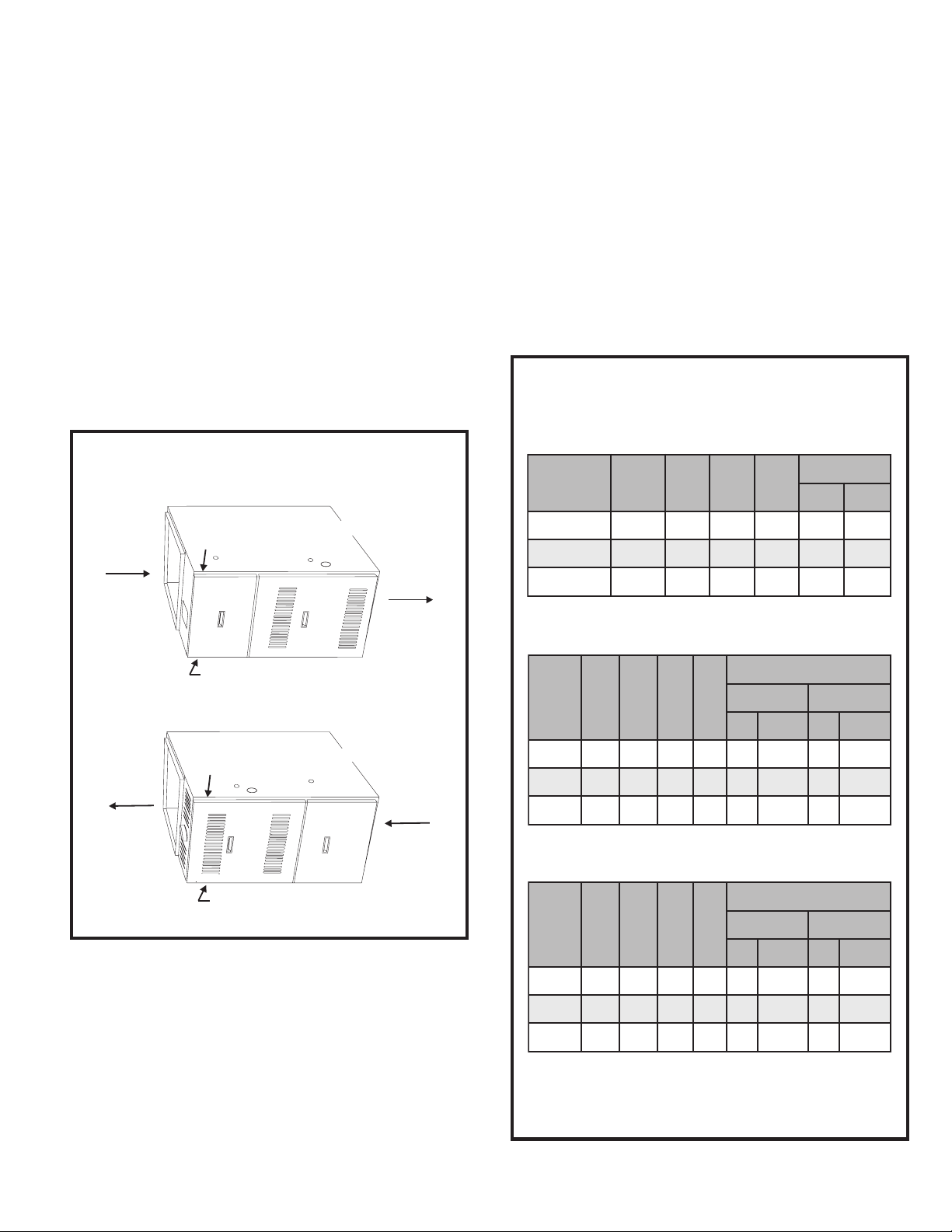
Air openings in the front of the furnace must
be kept free of obstructions. Any obstruction
may cause improper operation that can result
in a fire hazard or carbon monoxide injury.
WARNING
Where servicing clearances are greater than clearances
to combustibles, servicing clearances take precedence.
G1D80BT, G2D80CT, and horizontally installed G1D80BR
and G2D80CR models may be installed on wood flooring,
but shall not be installed directly on carpeting, tile, or other
combustible material other than wood flooring.
G1D80BR and G2D80CR models installed as counterflow
(downflow) units may be installed on combustible flooring
provided a special combustible floor base is used. See
Counterflow (Downflow) Installations on page 14 for
more information. Refer to unit rating plate for combustible
floor base part number.
Location
All models are suitable for closet or utility room installation.
The furnace must be installed so that electrical compo-
nents are protected from water.
The furnace is suitable for installation in buildings con-
structed on-site. The furnace should be centralized in
respect to the heat distribution system as much as
practicable. When installed in a utility room, the door
should be wide enough to allow the largest part of the
furnace to enter, or to permit the replacement of another
appliance, such as a water heater.
A gas-fired furnace for installation in a residential garage
must be installed so the burner(s) and the ignition source are
located not less than 18" above the floor. The furnace is to be
located or protected to avoid physical damage by vehicles.
This furnace is not recommended to be used as a construc-
tion heater during any phase of construction. Very low return
air temperatures, harmful vapors, and operation of the unit
with clogged or misplaced filters will damage the unit.
The furnace may be used for heating of buildings or struc-
tures under construction, if the following conditions are met:
• The vent system must be permanently installed per
these installation instructions.
• A room thermostat must control the furnace. The use
of fixed jumpers that will provide continuous heating is
not allowed.
• The return air duct must be provided and sealed to
the furnace.
• Return air temperature range between 60°F and 80°F
must be maintained.
• Air filters must be installed in the system and must be
maintained during construction.
• Air filters must be replaced upon construction completion.
• The input rate and temperature rise must be set per
the furnace rating plate.
• One hundred percent (100%) outdoor air must be
provided for combustion air requirements during construc-
tion.Temporary ducting may supply outdoor air to the
furnace. Do not connect duct directly to the furnace. Size
the temporary duct following the instructions given on the
next page in the Combustion and Ventilation Air
section regarding confined space with air from outside.
• The furnace heat exchanger, components, duct
system, air filters, and evaporator coils must be thor-
oughly cleaned following final construction cleanup.
• All furnace operating conditions (including ignition,
input rate, temperature rise, and venting) must be
verified according to these installation instructions.
G1D80BR, G1D80BT, G2D80CR, and G2D80CT models
installed in the horizontal position are approved for attic
installations. If the furnace is to be installed in an attic or
other insulated space, it must be kept free and clear of
insulating materials. When a furnace is installed in
conjunction with an evaporator coil in an attic or above a
finished ceiling where condensate overflow could result
in property damage, a drain pan should be provided
under the units as specified by most local building codes.
These furnaces may be installed as suspended units in the
horizontal position.These furnaces are not designed for
direct attachment of suspension rods to the furnace casing.
The suspending means must be field fabricated, and
should consist of two “cradles” made by attaching two
rods to a length of angle iron or suitable gauge steel.
Locate the cradles as close as possible to the ends of the
furnace (this will provide access for removal of major
components such as the blower assembly). Provide
enough clearance between the suspension rods and the
furnace to allow removal of access panels.
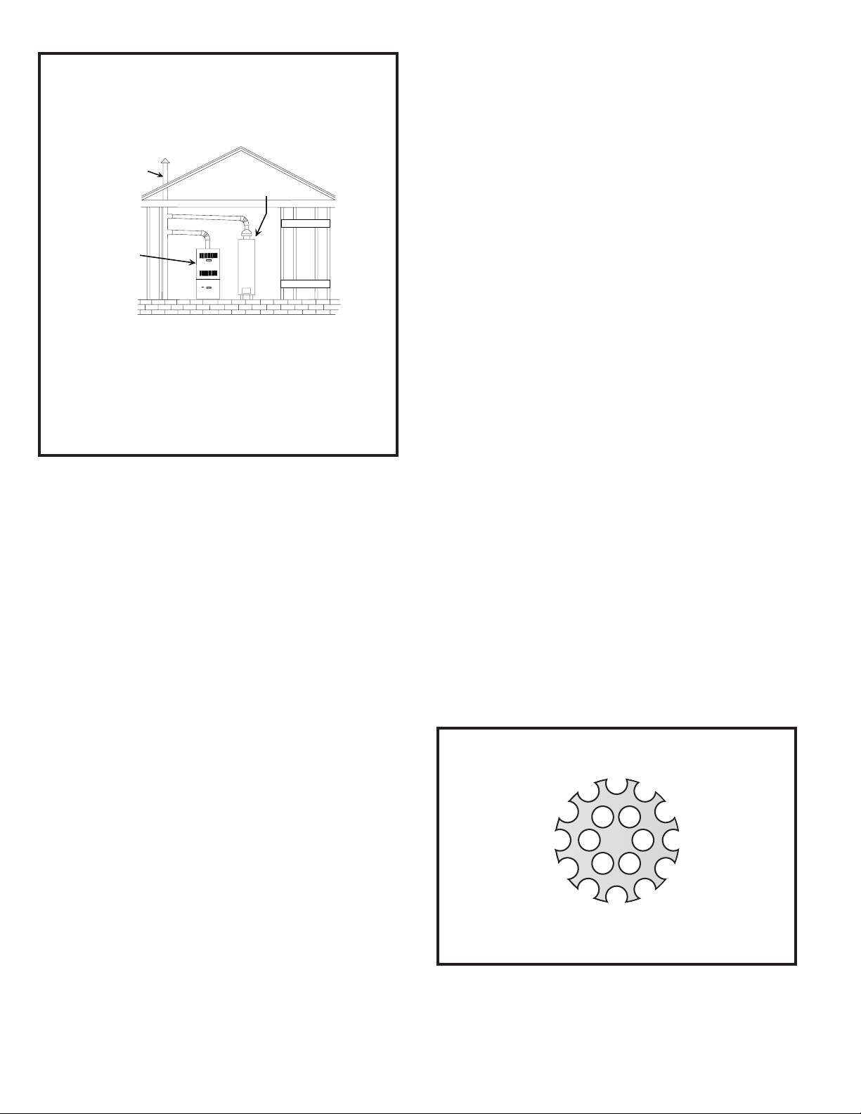
Combustion and Ventilation Air
Adequate provisions for combustion air and ventilation of
furnace must be made. Refer to Section 5.3, “Air for
Combustion and Ventilation,” of the National Fuel Gas
Code, ANSI Z223.1/NFPA54 (latest edition), Sections 7.2,
7.3, or 7.4 of CSA B149.1 Natural Gas and Propane
Installation Codes (latest editions), or applicable provi-
sions of the local building codes.