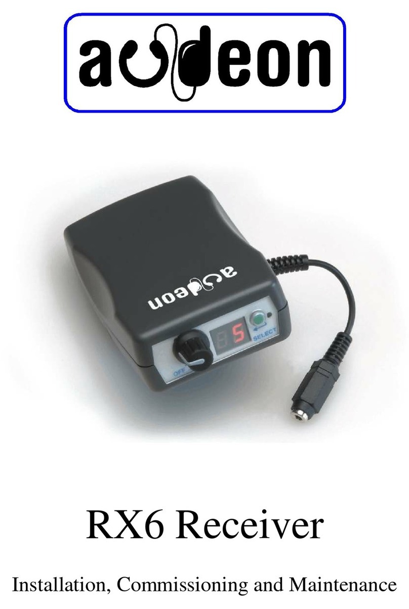
Audeon RX7 Receiver Maintenance and service guide

RX7 Receiver
Installation, Commissioning and Maintenance

Page 1 of 7
RX7 Receiver
Installation, Commissioning and Maintenance
This note appliesto the RX7 receiver and describes the installation of the system into a fitness studio, though
it is applicable to many other situations.
Introduction - RX7 Receiver
The RX7 is a 16 channel stereo UHF radio receiver designed as part of the Audeon wireless audio system. It
receives frequency modulated radio signals with Zenith-GE stereo encoding in the 864 MHz ISM band and in
TV channel 69 (854 MHz to 862 MHz). Production of the RX7 receiver commenced in September 2006.
The RX7 has facilities to enable the installer to reassign the channel frequency allocation and to reduce the
numberofavailablechannelswhicharereceived.Thisfacilitywillallowthereceptionofsignalsfromthesingle
channel transmitters where the frequency allocation requires non harmonically related carriers.
Operating the receiver
Connect a suitable pair of headphones to the 3.5mm jack socket. If the display is not already lit, the unit will
switchon when theexercise equipment is in use. The display shows thechannelselected.Pressingtheup arrow
underneath the display increments the channel number, until all channels have been selected when it returns
to channel ‘1’. Pressing the ‘+’ and ‘-’ buttons will increase or decrease the volume. Avoid increasing the
volume control before wearing the headphones as the sound may be very loud and uncomfortable.
Installation of the system
Initial testing
After the successful installation of the transmitter (see appropriate instructions for either the MCTX or the
SCTX). Because theRX7 does not have an internal battery you willneed totest the reception with the receiver
connectedto exercise machines in a number of locations around the gym. Anyproblems at this stage should be
addressed and the transmitter aerial re-sited if required. You should expect to have a minimum 90% coverage

RX7 Receiver - Installation, Commissioning
and Maintenance
Page 2 of 7
in most venues but metal pillars and similar objects which are in direct line of sight will obstruct the radio
signals
Installing the Receivers
The receivers are supplied with the internal jumper link set to 8 channel operation unless the installer has
requested a different frequency plan. The PIC microcontroller which is inside the receiver has the software
version indicated on its label and it is also displayed following the ‘HELLO’ message.
Changing the number of channels from the standard 8 channel frequency plan to the standard 16 channel plan
can be done either in hardware or software.
Changing the Frequency Plan in the Hardware
Tochange fromthestandard8channelto16 channeloperation,openthereceiverbyunscrewingthethreesmall
pozidrive M2.5 screws, the case can then be gently pulled apart to reveal the electronic PCBs. The main
receiver PCB designated RX710 has the jumper link (LK1) in one corner. Remove the jumper link so that the
two pinsare notconnected then fasten thetwo halves of the receiverback together making sure that the boards
locate together correctly.
Entering the Software Programming Mode
Whenfirst connectingthe equipmentthe installer will need to access the programming mode by holding down
the channel select switch whilst connecting the receiver until the flashing letter ‘P’ appears. After displaying
the letters ‘H E L L O’ followed by a ‘1’ (the software version) a flashing letter ‘P’ (for programming mode)
will be displayed. The receiver is now in programming mode and the letter ‘A’ is displayed. Pressing the
channel select button will cycle through the three menus ‘A’, ‘L’ and ‘C’. Holding the channel select button
down whilst one of the letters is displayed will allow the installer to select options from that menu.
Selection of the required frequency plan is achieved by using one of the three menus.
Menu ‘A’ Alternate Frequency Plan
Selecting this menu will enable the installer to easily select a number of popular predefined frequency plans.
Thesearedesignedforthelowest intermodwhenusingsinglechanneltransmittersinaninstallation.Pleasenote
that to avoid crosstalk and intermodulation we do not recommend using single channel transmitters on more
than 4 frequencies within the licence free band (863MHz to 865MHz). The frequency assignments for these
plans are shown in appendix ii.
When ‘A’ is displayed hold the channel select button down until ‘-’ is displayed, release the button and a ‘1’
is now displayed. To select this as the required frequencyplan press the channel select button until ‘F’ (finish)
is displayed.The plan for selection1has now been written to the EEPROM along with the lastchannel number
to be displayed (in this case a 1). Switch the receiver off and the new frequency plan will be effective when the

RX7 Receiver - Installation, Commissioning
and Maintenance
Page 3 of 7
receiver is switched on. Do not hold the channel select button down whilst ‘HELLO’ is displayed unless you
wish to re-enter the programming mode.
The selection can be easily changed back to the standard frequency plan using menu ‘C’ (see ‘C’ to clear
selection), or reprogrammed with analternateplan ‘A’ or placed in learn mode ‘L’. To select a new frequency
plan from those in appendix ii proceed as above. On switch on hold the channel select button down until ‘P’
flashes, select ‘A’ andholduntilthe ‘-’appears.Nowselectthe required new frequency plan. This time choose
the 4 channel plan which will reallocate the standard frequencies allocated to channels 1, 3, 6 and 8 to a new
plan where they will appear channels 1, 2, 3 and 4 on the display. Press the channel select button until ‘4’ is
displayed,thenholdthe button down until ‘F’ for finish isdisplayed. The EEPROM has now been updatedwith
the newplan, thenumberof channelsselected hasbeensaved as 4and the flagin the programmemoryhasbeen
reset for frequency plan number 4.
Menu ‘L’ Learn a new plan
This menu will allow the installer to create a frequency plan to suit the venue. Sometimes frequencies are
required in TV channel 69 and others in channel 70. This is often the case where radio microphones are in use
on the same site.
Hold the selector button down when ‘L’ is displayed until the ‘-’ is displayed. Release the button and ‘1’ is
displayed.Frequencieswhicharenot requiredaredeletedfromthefrequencyplan,soassumingthatfrequencies
allocated in the standard frequency plan (appendix i) for channels 2, 4 and 16 are to be deleted, press the
selector button once so that ‘2’ isdisplayed. Now press the button until ‘E’ (erase) flashes. When the ‘E’ stops
flashing the next channel number (3) will be displayed and the receiver has removed channel 2 from the
frequency plan. The number 3 is now showing on the display, you require this frequency so press the button
once so that the number 4 is displayed. Channel 4 is not required so press and hold down the button until ‘E’
(erase) flashes. When the ‘E’ stops flashing number 5 will be displayed. Channels 5 to 15 are required so press
the button once for each of these. At channel 16 which is not required hold the button down until ‘E’ flashes.
When ‘E’ stops flashing the number 17 will be displayed for a short time followed by ‘F’ (finish). The new
frequency plan has been written to the EEPROM, the last channel number has been set for the new total of
requiredchannelsandthe programmemoryflaghasbeensetinsidethereceivertoindicatethat anewfrequency
allocation has beenset. Turnthe receiver off,thenswitch it on again to check the new frequency plan. You will
have a totalof 13channels which have been reallocated to the frequencies which were not deletedinascending
order.
To change the channels to a different plan repeat the above learn mode ‘L’ or use the allocation mode (A) or
the clear mode to return to the standard frequency plan.
Menu ‘C’ Clear selections
This menu allows the installer to quickly reset the channel frequency plan to the standard frequency plan.
Hold the selector button down whilst ‘C’ is displayed until ‘-’ is displayed. Release the button and ‘F’ (finish)
is displayed. The EEPROM has been reset to the originalsettings. Switch the receiver offand when you switch
it on again the original factory settings will be restored.

RX7 Receiver - Installation, Commissioning
and Maintenance
Page 4 of 7
Fastening the Receiver to a machine
Fasten the receiver to the machine in a position where the receiver is
easily accessible for the user and it is out of the way of moving parts.
The receiver should be attached using the two 7.6mm wide cable ties
(supplied) which are fed through the appropriate holes in the receiver
mounting plate. The receiver can be attached at any orientation - in
multiples of 45/- to the bar to which you are fixing it. Choose holes in
the bracket which give the strongest pull and the closest fixing. The
mountingplateisdesigned so that itcan be fastened to differentsizesof
barand this canbe seenbythesteppedshapeofthemoulding.Checkfor
the appropriate mounting position and then select the correct holes for
the cable tie. The cable tie should be a snug fit round the equipment bar
so that the greatest surface area of the tie is in contact with the bar to
reduceslippage. For bars with a polished surface where friction is poor
athin layer of neoprene rubber (one non-slip mat is supplied for each
receiver) can be used to increase the friction. Farnell sell a suitable
material ‘multigrip anti-slip mat’ (their part no. 152 - 150B) which can
be cut to size (75mm × 55mm). One roll will provide approximately 50
pieces. Note that the users will probably play with the receiver during
exercise so make sure it is firmly attached to the machine. Extra cable
ties and non-slip mats are available from the factory.
Connecting the power lead to the CSAFE outlet
The power cable should be connected to the 8 pin RJ45 socket on the machine and then fixed down so that it
cannot interfere with the user or the moving parts of the machine. Check that the receiver is working. Signals
shouldbe received on all channels.Unplugthe headphonesand check that the receiver goesinto standbymode
afterapproximately 2 minutes, when the sound ismuted. The receiverwill operate and return to the state itwas
in before the headphone lead was removed as soon as the headphones are reconnected or the channel select
button is pressed once. When connecting the RX7 to a self powered machine you will have to operate the
machine whilst testing the operation,an assistant will probablybe required for this test. Some equipment may
have a CSAFE socket which has not been enabled or no CSAFE outlet.
The installation procedure should be repeated for all of the receivers.
Changing the headphone lead
Tochange theheadphone lead,insertasmall(4mm)screwdriverinto
the rectangular hole between the end of the plastic part of the
headphone lead and the box. Twist the screwdriver to lever out the
plastic insert. When inserting a new headphone lead, be careful not
to bend the metal pins of the connector on the circuit board.

RX7 Receiver - Installation, Commissioning
and Maintenance
Page 5 of 7
Other facilities
Hours Used Counter
The receiver will record the total time that the unit has been operating which will provide the factory with
useful information when the receiver is serviced.
Switch On Counter
This counter will record the number of times the receiver has been switched on so that we can determine how
much use the receiver has had. It can only be read at the factory during a service.
Headphone Disconnect Counter
Thiscounter records the number of timestheheadphoneshavebeenremovedwhenthe receiver is switched on.
Like the Switch On Counter above it willprovide information onthe receiver’suse and can onlybe readat the
factory.
Software Version
The current software version is indicated following the ‘HELLO’ message. For version 1 software a ‘1’ is
displayed, so you may not notice this before the first channel is displayed.
User maintenance
The venue staff should be instructed on how to operate the receivers and how to do simple maintenance. The
receivers should be cleaned after use with a damp cloth toremove anysweat and to stop a build up of bacteria.
The receivers should be checked once a week for malfunctions.
The headphone lead is also the aerial and reception will depend on the lead being in good condition.
Deterioration ofthe headphone lead will cause poor reception andcracklingin the headphonesandwill require
changing after approximately three months depending on use. You should demonstrate to the staff how to
change theheadphoneleadandoffertoleave somespareones.Youshould alsoexplain that theheadphone lead
is a consumable item and therefore does not have a warranty.
Spare parts
Spare headphone leads are available from the manufacturer, we suggest that you leave a price list with the
operator.

RX7 Receiver - Installation, Commissioning
and Maintenance
Page 6 of 7
Service
In the UK Audeon has a dedicated service line (0113 252 5582) to coordinate maintenance and repairs of
Audeon equipment. The operator should be made aware of the benefits ofexpert advice and support. The
telephone line is staffed by experienced engineers who are familiar with the Audeon range of products. They
can provide advice, online help and will arrange for maintenance from you, the dealer, if required. A poster is
provided with the help line telephone number for display on the staff notice board.
User Instruction
Before leaving the installation ensure that the staff are;
• Familiar with the system.
• Know about it’s features and benefits.
• They can demonstrate it to the users.
• They know how to maintain it and keep it clean.
• They can change the headphone lead.
• They know how to obtain service for the system.

RX7 Receiver - Installation, Commissioning
and Maintenance
Page 7 of 7
Appendix I Standard Channel Plan - Radio Frequencies
ISM licence free band UHF channel 70
Channel 1 863A10 MHz
Channel 2 863A35 MHz
Channel 3 863A60 MHz
Channel 4 863A85 MHz
Channel 5 864A10 MHz
Channel 6 864A35 MHz
Channel 7 864A60 MHz
Channel 8 864A85 MHz
TV channel 69 (licence required from JFMG in UK)
Channel 9 854A60 MHz
Channel 10 855A90 MHz
Channel 11 856A90 MHz
Channel 12 857A60 MHz
Channel 13 858A70 MHz
Channel 14 859A30 MHz
Channel 15 860A20 MHz
Channel 16 861A00 MHz
Appendix ii Reallocation of channels - Alternate Frequency Plans
Selectedfrequenciesareassignedtoconsecutivechannelnumbers.Eachfrequencynumberreferstothechannel
number associated with the required frequency in the standard frequencyplan (appendix i)
Plan No. Frequencies selected Last Channel No.
1 1 1
21 & 3 2
31, 3, & 6 3
41, 3, 6 & 8 4
51, 2, 4, 6 & 8 5
61, 2, 4, 5, 7 & 8 6
71, 2, 3, 4, 5, 6 & 7 7
81, 2, 3, 4, 5, 6, 7, & 8 8
91, 2, 3, 4, 5, 6, 7, 8 & 9 9
10 1, 2, 3, 4, 5, 6, 7, 8, 9 &10 10
11 1, 2, 3, 4, 5, 6, 7, 8, 9, 10 &11 11
12 1, 2, 3, 4, 5, 6, 7, 8, 9, 10,11 &12 12
13 1, 2, 3, 4, 5, 6, 7, 8, 9, 10,11, 12 & 13 13
14 1, 2, 3, 4, 5, 6, 7, 8, 9, 10,11, 12, 13 & 14 14
15 1, 2, 3, 4, 5, 6, 7, 8, 9, 10,11, 12, 13, 14 & 15 15
16 1, 2, 3, 4, 5, 6, 7, 8, 9, 10,11, 12, 13, 14, 15 &16 16

Fastening the RX7 to exercise equipment
The bracket for the RX7 is designed to fit round or square bars of
differing sizes. It is important that the correct cable ties are used and they are fed through the
correct holes in the mounting bracket to avoid premature failure due to distortion of the bracket.
The following photos show both the correct and incorrect ways to fasten them to equipment.
Smaller round bars
Correctly fastened to a round bar using 7.6mm cable ties, a non
slip mat and the inner mounting holes - no distortion of the
bracket. The bracket must be securely fastened on to the exercise
equipment to prevent the users “playing with it” and the wires
coming loose and fracturing.
Incorrectly fastened bracket using the outer mounting slots - bracket distorted and will then fail
in use due to the stress placed on the central mounting screw hole. This occurs when users try
to move the receiver whilst exercising.
Correctly fastened bracket attached to a large flat or round bar - no distortion of the bracket
For further information please contact the Audeon service line 0113 252 5582
Table of contents
Other Audeon Receiver manuals
