Australian Hydronic TIEMME User manual

•
page -
1
-
Australian Hydronic Supplies
10 Frankston Gardens Drive
Carrum Downs, Victoria,
Australia 3 01
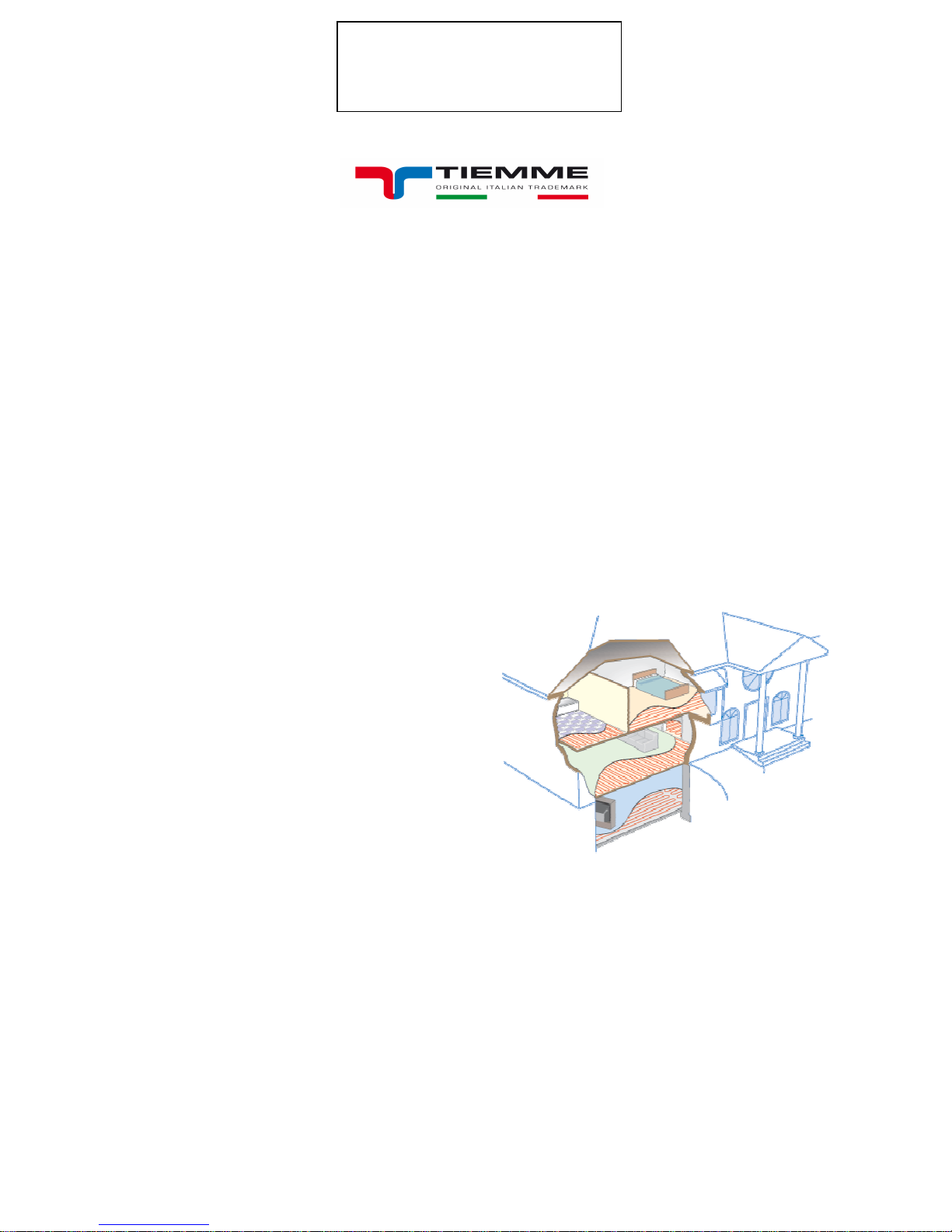
HYDRONIC RADIANT HEATING SYSTEM
Hydronic radiant heating & cooling systems can be installed in many ways to create a wonderfully
warm room environment.
These include:
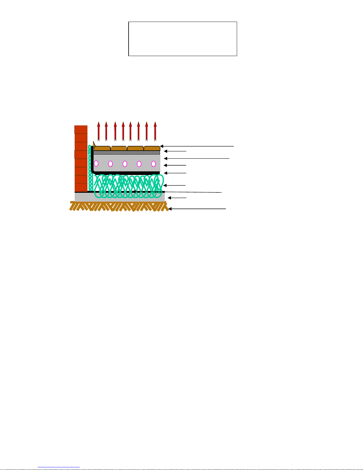
1. Pipes embedded in the concrete floor.
. Pipes in a floating floor system.
3. Pipes fixed to the underside of a wooden floor.
4. Pipes embedded in the walls of a room.
5. Pipes embedded in the ceiling of a room.
6. All these methods offer many practical benefits to suit the needs of all.
7. Hydronic radiant heating has been used for centuries. In the last few years, significant improvements in
the technology together with the realisation of the benefits of this form of heating and cooling have created
a rapid rise in installations. Tiemme has been one of the companies leading the way.
Benefits - Tiemme radiant floor, wall or ceiling
heating, provides energy saving with comfort, quiet
and clean operation, with room versatility and choice
of energy usage.
Energy Saving - Room temperatures can be set as
much as degrees lower and still maintain the
required comfort level. In houses with high ceilings the
savings can be significant.
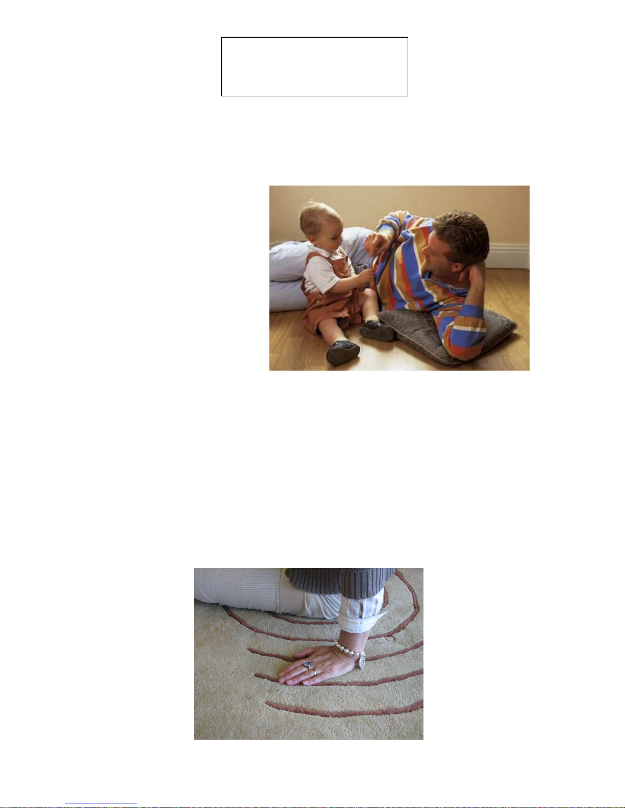
Ultimate Comfort - Rooms can be heated to different
temperatures according to their usage. Zones can be
set to heat rooms at different times to eliminate cold
rooms often during a relative short period of usage.
The floors are always comfortably warm no matter
what the floor coverings are.
Quiet Operation - Tiemme radiant floor heating
systems operate without noise and draughts. Air movement is kept to a minimum so dust and germs are not spread
around the house.
Choice of Surfaces - Tiemme radiant heating systems can be installed in a concrete floor on the ground or
suspended below with wooden floors and even in the walls or ceiling. The choices are unlimited.
Freedom to decorate - As the heat gently radiates from the whole of the floor there are no obstructions or
limitations for the placement of furniture.
Choice of energy – Tiemme radiant systems can be powered by a gas-fired boiler, a combination of heat pump
and solar collectors, solid fuel boiler or any new energy system yet to be discovered. This means your heating
system is always ready for the future.
Healthy Choice - Over the years people who have switched from forced air to floor radiant heating have greatly
improved their allergy problems. This is attributed to less dust blowing around.
Zero maintenance - Once installed Tiemme radiant floor heating does not require routine maintenance or
cleaning.

•
page -
2
-
Australian Hydronic Supplies
10 Frankston Gardens Drive
Carrum Downs, Victoria,
Australia 3 01
The following manual will show you
How radiant under floor heating is
-selected
- installed
- operated
A l l f o r y o u r b e n e f i t
P l e a s e r e a d t h i s m a n u a l c a r e f u l l y
1.0 INTRODUCTION. .................................................................................................... 3
.0 RADIANT UNDER FLOOR HEATING: ................................................................... 4
3.0 HEAT LOSS CALCULATIONS............................................................................... 6
4.0 PLANNING - LAYING OUT THE SYSTEM. .......................................................... 11
5.0 USEFUL INFORMATION ........................................................................................ 1
5.0 USEFUL INFORMATION ...................................................................................... 1
6.0 SELECTING A HEAT SOURCE. .......................................................................... 13
7.0 INFORMATION FOR THE BUILDER: .................................................................. 15
8.0 HOW IT IS INSTALLED?...................................................................................... 16
9.0 MANIFOLD SYSTEM ........................................................................................... 0
10.0 EXPANSION VESSELS SIZING ........................................................................... 4
11.0 FLOOR COVERINGS ........................................................................................... 5
1 .0 HOW IS IT OPERATED? ...................................................................................... 6
13.0 OTHER FORMS OF MULTITHERM RADIANT SYSTEMS .................................. 6
14.0 WARRANTY DECLARATION ..................... ERROR! BOOKMARK NOT DEFINED.

•
page -
3
-
Australian Hydronic Supplies
10 Frankston Gardens Drive
Carrum Downs, Victoria,
Australia 3 01
1.0 Introduction
Tiemme radiant heating systems give exceptional comfort and safety, and offers substantially
lower running costs than other types of heating. It is also resistant to scale build up and is non
corrosive. Tiemme pipe has an oxygen barrier. The first Tiemme pipes were installed over twenty
five (50) years ago, since then many millions of metres of Tiemme pipe have been installed and
continue to give trouble free service.
Tiemme pipe is manufactured and certified in accordance to EN-ISO 15875 & IPP n⁰16 standards
1.1 Technical details
Material : PE-Xb CobraPex
Shock resistance: as low as – 100
o
C
Working Pressure: 10 Bar at +95
o
C
Density: 0.943 g/M
3
Tenacity: + 7 N/mm
Crack extension: %
E-module: N/mm
Dimensions outside diameter: 16 mm
Wall thickness: .0 mm
Coil length 1 0/300/600M
Volume content: l/100M
Weight: kg/100M
Bending radius at 20
o
C: 14 diameters
Oxygen diffusion Barrier EVOH
The COBRAPEX pipe with oxygen barrier EVOH is made of high density polyethylene chemically cross
linked (silani reticulation)
The COBRAPEX pipe reticulation is type “b” (PE-Xb) this process modifies the chemical structure in order
to:
-Increase the maximum working temperature (95⁰C or 110⁰C for short periods);
-Reduce the deformation under stress;
-Increase the resistance to chemical products;
-Increase the resistance to UV rays
-Increase the resistance to abrasions and hurts
-Increase the technical memory characteristics.
TIEMME
Offers the best solution for a safe radiant floor heating system
The objective of this manual is to assist with the selection and installation of radiant in a hydronic heating
system. The installer should have a mechanical services license and exercise a duty of care in all aspects
of the installation. Australian Hydronic Supplies Pty Ltd cannot be held responsible for the selection or
installation of any system.

•
page -
4
-
Australian Hydronic Supplies
10 Frankston Gardens Drive
Carrum Downs, Victoria,
Australia 3 01
.0 Radiant under floor heating
.1 How does it work?
”What exactly is radiant energy?” Hold your
hand over a hot cup of coffee and feel the
heat. The logical conclusion is that heat
rises. Logical maybe, but incorrect! “Hot
air” rises but “heat” can travel in any
direction. That is why you can feel the heat
of the cup when you place your hand near
the side of it. Radiant energy transfer is
caused by a warm surface giving up its heat
to a cooler surface. Place your hand on the
side of the cup and it will be heated through
conduction. Whenever there is a
temperature difference between two
surfaces, both surfaces will attempt to
equalize.
Radiant energy travels through space without heating the space itself. It only turns into heat when it contacts a
cooler surface. Our human comfort relies just as much on radiant heat transfer as it does on air temperature, yet
the majority of heating and air-conditioning professionals think only in terms of air temperature. As a result,
Australians are missing the ultimate comfort available from radiant floor heating in their own homes or places of
business. By controlling both the air temperature and the radiant transfer, radiant under floor heating can deliver
comfort that is unsurpassed. The system delivers a continuous flow of warm water at a temperature as near as
possible to the optimum temperature required to maintain comfort conditions. For the same comfort level the room
air temperature can be °C lower because radiant heat warms the surfaces rather than the air around the surfaces.
This means you feel more comfortable. The lower temperature means less fuel is consumed and the system is
more economical, saving more money every year.
# a thought for the day #
If hot air ducted heating is so great, why are there so many duct-cleaning
companies?

•
page -
5
-
Australian Hydronic Supplies
10 Frankston Gardens Drive
Carrum Downs, Victoria,
Australia 3 01
How is it selected?
. .1 Getting started
A qualified heating engineer or a qualified mechanical services installer should select your radiant
underfloor heating system.
. .3 The heated floor
The slab will naturally dissipate heat through the media in an upward direction and provide uniform heat
transference. Downward heat into the subsoil is lost energy and can be minimised with the use of
appropriate under slab insulation.
The system is selected to provide the following conditions:
Flow temperature of the water 40 – 55
o
C
Surface temperature of slab 5 – 30
o
C
Room temperature 0 – 3
o
C
Heat output @ 200mm centres: 140 W/m
. .3 Concrete thickness
The thickness of the concrete slab will be determined by relevant building regulations and as such will be suitable
for floor coil heating. It is important that a uniform cover be maintained between the top of the pipe and slab surface
to ensure even floor temperature.
Minimum cover 30mm
Maximum cover 50mm
Minimum slab thickness 100mm
The following information is to be provided at selection stage:
1. Tiemme Cobra-Pex pipe specified
2. Pipe dimensions 16 dia x 2.0 wall
. Pipe spacing
4. Required length of pipe on each circuit
5. Required flow rate through system
6. Manifold specifications and location
7. Boiler specifications and location
8. Thermostat specifications and location
9. Installation lay-out of pipe runs
Australian Hydronic Supplies is able to provide backup technical support for both specifiers and installers of
Tiemme radiant underfloor heating systems and provide the necessary equipment to install this fantastic system of
heating. Please refer to the shopping list in section 7.2.
All design and specification work is to be approved by a qualified heating engineer or hydraulic consultant before
commencement of work.

•
page -
6
-
Australian Hydronic Supplies
10 Frankston Gardens Drive
Carrum Downs, Victoria,
Australia 3201
3.0 Heat loss calculations
All heat loss calculations should be made by a suitably qualified person, so that the building is not over or
under capitalised on the heating equipment. Over capitalised means too much money has been spent, but
the system will perform very well. Under capitalised means the system will never reach the expectation of
the owner and cannot be improved, even at many times the cost of the original savings made.
3.1.1 Floor coverings heat transfer
As part of the heat loss calculation, consideration has to be made for the floor coverings to be used. The
most efficient materials to use for floor coverings are those that have a high rate of conduction, (a low
thermal resistance) thus can conduct the heat from the floor and radiate its warmth to you. As a rule, a
maximum R-value of 0.15m
K/W is best for the floor covering. The following table illustrates more common
floor covering materials. Actual rates should be obtained from the supplier.
Floor Covering
Nominal Thickness
R
-
value
Ceramic tiles
12 mm including mortar base
0.01
Stone or marble
25 mm including mortar base
0.01
Wood
10 mm including adhesive
0.05
Vinyl
5 mm
0.02
Carpet
10mm including underfelt
0.15
1.
Ideal Heating Curve
2. Radiant Floor Heating
. Radiators on Inside
Walls
4. Radiators on Outside
Walls
5. Forced Hot Air Heating
6. Ceiling Heat

•
page -
7
-
Australian Hydronic Supplies
10 Frankston Gardens Drive
Carrum Downs, Victoria,
Australia 3 01
Heated Room
Concrete
Concrete Slab
Moisture Barrier
PS Insulation
Compacted Fill
Consolidated Earth
Tiemme pipe
Heated Room
3.1. Slab construction
Examples of slab constructions are detailed below:
Moisture Barrier
Compacted Fill
Consolidated Earth
Distance from top of pipe
to surface of concrete -
Maximum 65 mm
Minimum 30 mm
Pip
FIG. 1 General installation
Heated Room
Pip
FIG. 1 General installation
Heated Room

•
page -
8
-
Australian Hydronic Supplies
10 Frankston Gardens Drive
Carrum Downs, Victoria,
Australia 3 01
The cost benefit of each method of construction should be considered by the heating engineer
and your builder before construction commences
.
FIG. 2 pipe in slab with insulation
Consolidated earth
Concrete
slab
Moisture Barrier
Insulation
Polyethylene membrane
Mortar
Bed
Tiles
Screed
Tiemme pipe
FIG. 3 Pipe in Screed installation
Heated Room

•
page -
9
-
Australian Hydronic Supplies
10 Frankston Gardens Drive
Carrum Downs, Victoria,
Australia 3 01
3. Heat output
Tiemme 16mm x .0mm pipe
Calculate the heat output at various room and water flow temperatures of 30
o
C
Floor
covering Pipe spacing
Room temp
15
o
C
Room temp
18
o
C
Room temp
0
o
C
Room temp
22
o
C
Room temp
24
o
C
mm
W/M
2
–
Floor
o
C
W/M
2
–
Floor
o
C
W/M
2
–
Floor
o
C
W/M
2
–
Floor
o
C
W/M
2
–
Floor
o
C
Masonry
tiles
50
107
–
22.6
86
–
24.1
71
–
5.1
58
–
26.1
44
–
27.1
100
100
–
22.1
80
–
2 .1
67
–
4.8
54
–
25.9
40
–
26.9
150
92
–
21.6
7
–
2 .2
61
–
4.4
50
25.6
7
–
26.6
200
85
–
21.1
67
–
22.8
56
–
4.0
45
–
25.2
4
–
26.4
25
75
–
20.4
60
–
22.
50
–
3.6
40
–
24.9
0
–
26.1
00
65
–
19.6
5
–
21.8
44
–
3.1
5
–
24.5
26
–
25.9
PVC
parquetry
50
90
–
21.4
79
–
2 .6
60
–
4.3
8 24.7
28
–
26.0
100
84
–
21.0
70
–
2 .2
56
–
4.0
6
–
24.6
26
-
25.9
150
78
–
20.6
68
–
22.8
51
–
3.6
–
24.4
24
–
25.7
200
70
–
20.0
61
–
22.4
47
–
3.4
0
–
24.1
22
–
25.6
250
6
–
19.5
55
–
21.9
4
–
3.0
27
-
2 .9
20
–
25.4
00
55
–
18.9
48
–
21.4
37
–
.8
24
–
2 .7
18
–
25.2
Carpet
50
71
–
20.1
58
–
22.1
47
–
3.4
8
–
24.7
28
–
26.0
100
67
–
19.8
54
–
21.9
44
–
3.1
6
–
24.6
26
–
25.9
150
62
–
19.4
50
–
21.6
41
–
.9
–
24.4
24
–
25.7
200
56
–
19.0
46
–
21.
37
–
.6
0
–
24.1
22
–
25.6
250
51
–
18.6
41
–
20.9
34
–
.4
27
–
2 .9
20
–
25.4
00
45
–
18.2
7
–
20.6
30
–
.1
24
–
2 .7
18
–
25.2
Calculate the heat output at various room and water flow temperature of 35
o
C
Floor
covering Pipe spacing Room temp
15
o
C
Room temp
18
o
C
Room temp
20
o
C
Room temp
22
o
C
Room temp
24
o
C
mm
W/M
2
–
Floor
o
C
W/M
2
–
Floor
o
C
W/M
2
–
Floor
o
C
W/M
2
–
Floor
o
C
W/M
2
–
Floor
o
C
Masonry
tiles
50
14
–
25.4
122
–
26.7
108
–
7.7
80
–
28.7
80
–
29.7
100
1 4
–
24.6
114
–
26.2
100
–
7.
87
–
28.2
74
-
29.
150
12
–
2 .8
105
–
25.5
9
–
6.6
80
–
27.7
68
–
28.8
200
112
–
2 .0
95
–
24.8
84
–
6.0
72
–
27.2
62
–
28.4
250
100
–
22.1
85
–
24.1
75
–
5.3
64
–
26.6
55
–
27.9
00
88
–
21.
74
–
2 .
66
–
4.7
57
–
26.1
48
–
27.4
PVC
parquetry
50
120
–
2 .6
102
25.
90
–
6.5
77
–
27.6
66
–
28
-
7
100
112
-
2 .0
96
–
24.8
84
–
6.0
7
–
27.2
62
–
28.4
150
104
–
22.4
88
–
24.
77
–
5.6
67
–
26.8
57
–
28.1
200
94
–
21.7
80
–
2 .7
70
–
5.0
61
–
26.4
52
–
27.7
250
84
–
21.0
71
–
21.1
63
–
4.5
54
-
25.9
47
-
27.
00
7
–
20.
62
–
22.4
55
–
3.9
47
–
25.4
41
–
26.9
Carpet
50
95
–
21.8
80
–
2 .7
71
–
5.1
61
–
26.4
51
–
27.6
100
89
–
21.
75
–
2 .4
66
–
4.7
57
–
26.1
48
–
27.4
150
82
–
20.9
70
–
2 .0
6
–
4.4
8
–
25.8
45
–
27.2
200
75
–
20.4
64
–
22.5
56
–
4.0
48
–
25.4
41
–
26.9
250
68
–
19.8
58
–
22.1
51
–
3.6
44
–
25.1
7
–
26.6
00
60
–
19.
51
–
21.6
45
–
3.
9
–
24.7
–
26.

•
page -
10
-
Australian Hydronic Supplies
10 Frankston Gardens Drive
Carrum Downs, Victoria,
Australia 3 01
Calculate the heat output at various room and water flow temperature of 40
o
C
Floor
covering Pipe spacing
Room temp
15
o
C
Room temp
18
o
C
Room temp
0
o
C
Room temp
o
C
Room temp
4
o
C
mm
W/M
2
–
Floor
o
C
W/M
2
–
Floor
o
C
W/M
2
–
Floor
o
C
W/M
2
–
Floor
o
C
W/M
2
–
Floor
o
C
Masonry
tiles
50
180
-
27.8
158
–
29.
143
–
30.
1 0
–
29.
115
–
2.2
100
168
-
27.0
147
–
28.5
134
–
9.5
120
–
28.6
108
–
1.7
150
154
–
26.0
1 4
–
27.6
1
–
8.7
110
–
27.9
99
–
1.1
200
140
–
25.0
12
–
26.8
111
-
8.0
100
–
27.2
90
–
0.5
250
125
–
2 .9
110
–
25.9
100
–
7.
90
–
26.5
80
–
29.6
00
110
–
22.8
97
–
24.9
88
–
5.7
80
–
25.7
70
–
29.1
PVC
parquetry
50
150
–
26.7
1 2
–
27.5
1 0
-
8.6
108 29.7
96
–
0.8
100
140
–
25.0
124
–
26.9
11
–
8.0
101
–
29.
90
–
0.4
150
1 0
–
24.
11
–
26.1
103
–
7.4
9
–
28.7
8
–
29.9
200
117
–
2 .4
10
–
25.4
94
–
6.8
84
–
28.1
75
–
29.
250
105
–
22.5
92
–
24.0
84
–
6.0
75
–
27.5
67
–
28.8
00
92
–
21.6
81
–
2 .
73
–
5.
66
–
26.7
59
–
28.2
Carpet
50
118
–
2 .4
104
–
25.5
95
–
6.7
85
–
28.1
76
–
29.4
100
111
–
22.9
98
–
25.0
89
–
6.3
80
–
27.7
71
–
29.1
150
10
–
22.
90
–
24.5
8
–
5.9
74
–
27.
66
–
28.7
200
94
–
21.7
8
–
2 .9
75
–
5.3
67
–
26.8
60
–
28.7
250
85
–
21.0
75
–
2 .
68
–
4.8
61
–
26.
60
-
27.8
00
75
–
20.
66
–
22.7
60
–
4.3
54
–
25.8
48
–
27.4
Calculate the heat output at various room and water flow temperature of 45
o
C
Floor
covering Pipe spacing
Room temp
15
o
C
Room temp
18
o
C
Room temp
20
o
C
Room temp
22
o
C
Room temp
24
o
C
mm
W/M
2
–
Floor
o
C
W/M
2
–
Floor
o
C
W/M
2
–
Floor
o
C
W/M
2
–
Floor
o
C
W/M
2
–
Floor
o
C
Masonry
tiles
50
215
-
0.4
194
–
1.8
180
–
33.7
165
–
.7
151
–
4.8
100
200
-
29.
180
–
20.9
167
–
31.9
154
–
.0
140
–
4.0
150
184
-
28.2
165
–
29.8
15
–
30.9
141
–
2.1
129
–
.2
200
168
-
27.0
150
–
28.7
140
–
30.0
129
–
1.2
118
–
2.4
250
150
-
25.7
1 4
–
27.6
1 4
–
8.9
114
–
0.1
105
–
1.5
00
1 2
-
24.4
118
–
26.4
110
–
7.9
101
–
29.2
92
–
0.6
PVC
parquetry
50
180
–
27.8
162
–
29.6
150
–
30.7
1 8
–
1.8
125
–
2.9
100
167
–
27.0
151
–
28.9
140
–
30.0
129
–
1.2
117
–
2.4
150
154
–
26.0
140
–
28.0
1 9
–
9.
118
–
0.5
108
–
1.7
200
140
–
25.0
127
–
27.0
117
–
8.4
108
–
29.7
98
–
1.0
250
125
–
2 .9
114
–
26.1
105
–
7.6
96
–
28.9
88
–
0.
00
110
–
22.8
100
–
25.6
9
–
6.6
84
–
28.1
77
–
29.5
Carpet
50
141
–
25
127
–
27.1
118
–
8.4
109
–
29.8
99
–
1.0
100
1 2
–
25
120
–
26.6
111
–
7.9
102
–
29.
9
–
0.6
150
122
–
24
112
–
26.0
103
–
7.3
95
–
28.8
86
–
0.2
200
112
–
2
102
–
25.
94
–
6.7
86
–
28.2
79
–
29.6
250
102
–
22
92
–
24.6
85
–
6.1
78
–
27.6
71
–
29.6
00
90
-
22
81
–
2 .8
74
–
5.3
69
–
26.9
6
–
28.5
Note: Outputs shown thus 140 – 30.0 are the preferred combination of pipe spacing and room
temperature

•
page -
11
-
Australian Hydronic Supplies
10 Frankston Gardens Drive
Carrum Downs, Victoria,
Australia 3 01
4.0 Planning - laying out the system
Fig
4
Every system has to be precisely plann
ed to maximise the comfort and energy efficiency of the
system. The flexibility of the underfloor heating allows heating to be concentrated where needed most
and reduced where little or no heat is required. The closer the pipe spacing or deeper the pipe is
embedded in the screed the more uniform the heat distribution. Increasing the water temperature
increases the heat output of the heating system.
The diagrams below illustrate some of these possibilities:
4.1 Piping laying patterns
c)
System C
Combination system
This method allows greater heat to be applied to
the coldest area of the room, being the outside
walls often where there are large full-length
windows. Cold air cascading down these windows
is quickly heated by the concentrated heating on
the perimeter of the building to increase the
comfort of the room
FLO W
RETU RN
d
) System D
Localising the heat
distribution.
Whatever system A – C is used, where possible,
avoid placing piping under places such as kitchen
cupboards, refrigerators and also in the bathroom.
Heat can be concentrate for an airing cupboard or
sitting area. This all makes Tiemme underfloor
heating system a most practical system.
SYSTEM - D
C UPB O ARD S
a)
System A
Spiral Laying Pattern
This the most common method used as it gives a more
even heat distribution across the floor. Always lay the flow
pipe (hottest) nearest to the outside wall, with a distance of
150-200 mm from the inside of the finished wall. This
system has mainly 90
o
bends which are easier to lay than
180
o
bends
.
SYSTEM - A
R E TUR N FLOW
b)
System B
Serpentine Laying Pattern
This method is useful when laying above the concrete where
battens are used under a floating wooden floor. It also allows
the warmest floor to be closest to the coldest wall. Always lay
the flow pipe (hottest) nearest to the outside wall with a
distance of 150-200 mm from the inside of the finished wall
.
SYSTEM - B

•
page -
12
-
Australian Hydronic Supplies
10 Frankston Gardens Drive
Carrum Downs, Victoria,
Australia 3 01
5.0 Useful information
5.1 Water flow rates
Water flow rates can be calculated from the following formula:
Water Flow (l/s) = KW / x 4.187 x temp change
o
K - (K usually 10 – 15
o
K)
KW = water flow (l/s) x 4.187 x temp change
o
K
As a guide, water velocity in pipes should not exceed:
Residential – 0.7 M/s Industrial – 1.0 M/s
With a maximum pressure drop not exceeding 0kPa
Velocities and pressures above this will cause noise, erosion and circulation problems.
This will depend on the type of circulator used, the project conditions and function.
5. Heat load calculator
The following formula can be used to calculate the heat load of the room:
Room - Length x width x height x Factor
1000
Where factor = for bedrooms 40
for living rooms 50
Using the same example room:
a bedroom - 5 x 4.5 x 3 x 40 = .7 kW
a lounge - 5 x 4.5 x 3 x 50 = 3.4 kW
This means a living room would be warmer than a bedroom.
This method gives an approximation only. A full heat load calculation should be
done by a suitably qualified heating engineer.

•
page -
13
-
Australian Hydronic Supplies
10 Frankston Gardens Drive
Carrum Downs, Victoria,
Australia 3 01
6.0 Selecting a heat source
The choice of heat source for Tiemme floor heating is almost unlimited requiring only a flow and
temperature controlled water flow. The possibilities include; geothermal, gas-fired boilers, electric
boilers, wood-fired boilers and heat pumps. Of these, the gas-fired boiler is the most common.
Gas boilers
These can be categorised as the following:
TYPE D -
Condensing boilers
. These boilers offer
the highest efficiency and are ideal for the
low water temperatures required by the
Tiemme floor heating system. This type of
gas boiler is easy to plumb and control and
is highly recommended
TYPE B -
Cast iron boiler
. Long lasting simple control
system easy to plumb and control
TYPE A -
Storage boiler.
Usually with domestic hot
water capacity. Works well with floor heating
and is easy to plumb and control.
TYPE C -
Copper tube atmospheric boilers
.
Requires an additional pump to work, but
has better efficiency than atmospheric
storage or cast iron boilers.

•
page -
14
-
Australian Hydronic Supplies
10 Frankston Gardens Drive
Carrum Downs, Victoria,
Australia 3 01
6. Electric boilers
These can be categorised as the following:
(1) Off peak Laing electric boilers. An option when
natural gas is not available. Usually requires three
phase power to provide enough energy input for the
short time the boiler has to recover. For maximum
capacity, water has to be stored at the highest
temperature possible then mixed to a lower
temperature in use. This requires some form of
temperature controlled mixing valve. Running costs
similar to natural gas boilers but a very large storage
tank is required. Type B plumbing.
( ) Instantaneous electric boiler. Some new
electric boilers are becoming available which offer an
alternative mainly for smaller applications on single-
phase power. Day rate electric makes it more
expensive to run but it is compensated by the
efficiency of the Tiemme floor heating system giving a
far better heat distribution than a direct air heater of
similar capacity. Simple to install and control. Type D
plumbing.
(3) Electric heat pumps. These water heaters
provide the efficiency of the refrigeration multiplier to
give excellent running costs where natural gas is not
available. Further efficiency can be gained by using
ground or water sourced heat, however, this all adds
considerably to an already high capital cost of
installation. This method is mostly suited to large
commercial applications. It can also be used as a
reverse cycle heat pump to provide base load cooling
to a building through the same Tiemme floor system.
Type D plumbing.
6.3 Geothermal
This can be categorised as the following:
(4)
Although ground sourced warm to hot
water is available in many parts of the
country, very few systems have been
installed. This is due in part to the isolated
places where hot water is available, although
Portland in Victoria is one place where it is
utilised. Similarly cold water from rivers and
large dams can be utilised for base load
cooling.

•
page -
15
-
Australian Hydronic Supplies
10 Frankston Gardens Drive
Carrum Downs, Victoria,
Australia 3 01
7.0 Information for the builder
Full co-operation and communication between the builder and you the under floor heating installer is
required to co-ordinate the installation of the heating system during the construction phase of the
building.
7.1 Site requirements
As the Tiemme under floor heating installer, it is in your interest to ensure that the main contractor (the
builder?) and other trades are made aware of the requirements for a clear working space. This is
essential to ensure the smooth running of the contract and if you make these requirements clear to the
main contractor, the installation will be quick and correct.
1. The work site should be clear before commencement of work.
. Check who is responsible for the installation of the insulation, if specified.
3. Mains water must be available for the flushing and pressure testing of the system.
4. Any structural requirements are to be adhered to.
5. No go zones for the piping are to be marked out with YELLOW---LINES on the prepared site.
7. Shopping list - parts required for the project
Item Description
Quantity
required
Make
Model /
size
Supplier
Boiler
1
Australian
Hydronic Supplies
Room thermostat
-
Australian
Hydronic Supplies
Manifold kit
–
Tiemme
CIRCUITS
Tiemme
Australian
Hydronic Supplies
Pipe coils 18 x 2.2 x 100 M
COILS
Tiemme
Australian
Hydronic Supplies
Pipe ties 2 per metre of pipe
Australian
Hydronic Supplies
Mesh
M
2
Builder
Insulation
–
under floor
M
2
Australian
Hydronic Supplies
Insulation
–
wall
M
Australian
Hydronic Supplies
Main feed pipe boiler to manifold
2 mm
Australian
Hydronic Supplies
Zone control Valves
CIRCUITS
Australian
Hydronic Supplies
Zone control
thermostats
CIRCUITS
Australian
Hydronic Supplies

•
page -
16
-
Australian Hydronic Supplies
10 Frankston Gardens Drive
Carrum Downs, Victoria,
Australia 3 01
IMPORTANT.
The pipe should be stored indoors on a flat surface away fro any sources of heat, che icals or
echanical da age until required for use. When finished check that there is no da age to the outer
EVOH layer.
Should a pipe be kinked it can be repaired by the following method.
Use a hot air gun or similar to heat the affected area by applying heat over the general area. To
avoid overheating, keep the gun constantly moving for about – 5 minutes when the pipe should
recover.
When necessary to bend the pipe to the minimum radius, use the same method to warm the pipe
before bending.
Photo showing ellow lines
around NO GO ZONES.
8.0 How it is installed?
8.1 Before you start installing the pipe
1. All formwork has to be finished and mesh installed on all parts of
project prior to the laying Tiemme pipes.
. Fix the header firmly in at the selected position, preferably in the
centre of the system in a cupboard, storage room, laundry room,
linen room or utility room.
3. Cover the manifold to ensure that it is not damaged by wet
concrete during the pour.
4. Mark the manifold with the name of each circuit i.e. “lounge,”
“bedroom 2 & ” etc.
5. Lay out the polystyrene insulation over site.
6. Clearly mark the position of all external and internal walls and any
other no go zones. A suggestion is the use of yellow pressure pack
paint.
7. Check the selected laying pattern being used and the pipe
centres, remembering that with a spiral pattern the spacing
starts at twice the nominated centre distance. Refer to
Page 9.
8. Plan in which order the circuits are to be laid to avoid
having to cross other pipes or areas where internal walls,
cupboards, vanities, toilets etc. may be installed with the
use of concrete fasteners. Also do not lay pipes under any
open fireplaces or slow combustion heaters and other like
appliances.
Photo showing insulation
installed and pipe laid.
Tiemme
Manifold

•
page -
17
-
Australian Hydronic Supplies
10 Frankston Gardens Drive
Carrum Downs, Victoria,
Australia 3 01
8. Laying the pipe
1. Use a de-coiler to unwind the pipe off the coil without kinking
the pipe.
. Use conduit type cutter to produce a clean burr free cut
3. Lay pipes in either spiral or serpentine laying pattern as
selected Refer section 4.1
4. Securely fix the pipe to the mesh at a maximum of 600 spacing using plastic cable ties or
plastic coated copper wire – DO NOT USE BARE COPPERWIRE AS
THIS WILL VOID THE WARRANTY.
5. Fit corrugated sleeves around the pipes for one (1) metre from the
manifold into the slab. This gives added protection at the point of entry
and exit from the slab.
6. Start the circuit installation from the header out to the room entering and
exiting the selected room through the doorways only.
7. The length of all circuits should be approximately the same; ideally each circuit should be
the full length of the pipe coil (100 metre).
8.3 Construction – expansion joints
Where expansion joints in the concrete are required as
part of the building structure the following precautions
should be noted:
•Avoid crossing expansion joints wherever possible
•Where a crossing is unavoidable, ensure that the
pipe is at 90deg to the construction joint and that a
sleeved conduit is fitted over the pipe for a distance
of 200mm (minimum) either side of the expansion
joint.
200
minimum
200
minimu
Protective
sleeving
Tiemme
Pipe
Plan circuits to minimise the
number of pipe crossings of an
expansion joint

•
page -
18
-
Australian Hydronic Supplies
10 Frankston Gardens Drive
Carrum Downs, Victoria,
Australia 3 01
8.4 Pipe in screed installation method
1. Install Polystyrene insulation over the concrete
slab
. Place polyethylene membrane over the
insulation. Membrane prevents escape of the
water from the screed.
3. Install sound insulating edge strip along walls
and around ascending structural components.
E.g. door frames or columns.
4. Edge insulating strip is made from closed cell
PE foam and it allows for the expansion of the
heated screed and prevents thermal and
acoustic bridging to the outside wall.
5. Install pipes in either classic serpentine or
compacted marginal zone serpentine lying
pattern.
6. Integrated marginal zone serpentine laying
pattern provides more even temperature
distribution across the floor
8.4.1 Filling the system
1. The circuits must be flushed with water so that
they are free from air. The individual heating
circuits are flushed consecutively, during
which the heating valves for each other circuit
must be closed.
. Proceed as follows:-
3. Check that all manifold connections are tight.
4. Close fully ALL Flow valves and ALL return
valves.
5. Connect a hose to the flow Drain/Fill valve and
a hole from the return Drain/Fill valve to a
suitable visible drain point.
6. Open No. 1 flow and return valve. Turn on the
water, allow the all the air to purge through the
circuit until clear.
7. When satisfied there is no more air in circuit
No. 1. Close the return valve of No. 1 circuit.
8. Simultaneously close the flow valve of circuit
No. 1 and open the flow valve of circuit No. 2.
Then open the return valve of No. 2 to repeat
the purging of air in that circuit.
9. Repeat steps 4 to 6 until all circuits have been
purged of air. At this point the whole system
should be full of water and all the circuit valves
closed.
10.
Check that the main flow and return pipes
from the manifold to the boiler connections are
full of water by purging air from temporary air
bleed valves fitted to the capped ends at the
boiler location
.
8.4. Pressure testing the system
11. The system should be filled with water and bled of
all air though the air bleed valves fitted to the
manifolds and the main pipes to the boiler. (Refer to
filling the system 8.4.1 above).
1 . DO NOT USE COMPRESSED AIR.
13. Pressure test the system with the aid of a test
bucket and pressure gauges, to ensure that the
system is free of any leaks.
14. Proceed as follows:-
15. Open all flow and return valves.
16. Fill pressure pump and connect to system at a
convenient point out side of the concrete pour area.
17. Apply pressure to 6 Bar to the system.
18. Check all joins for leaks.
19. Re pressurise the system until the pressure
remains stable.
0. Note that the test pressure will be affected by
ambient temperature changes. A 10
o
C change
corresponds to a 0.5 – 1.0 Bar pressure variation. A
normal settled gauge pressure of between .5 and
4.5 Bar during testing would be satisfactory.
1. Leave the system under pressure with a visible
pressure gauge during the concrete pour to ensure
that any leaks caused by an improper concrete
pour are quickly found.
22. Check to see if the system is under pressure prior
to the pour and note the pressure at the gauge.

•
page -
19
-
Australian Hydronic Supplies
10 Frankston Gardens Drive
Carrum Downs, Victoria,
Australia 3 01
8.5 Pouring the slab
1. Ensure that the screed used in the concrete
is suitable for underfloor heating.
. To avoid possible damage to the pipe the
slab should be poured at the earliest
possible opportunity after the leak test has
been completed.
3. Ensure that the concrete vibrator probes do
not come into contact with the pipe.
4. Care must be taken to ensure that shovels
or other hand tools do not damage pipe
work.
5. Provide board walkways to facilitate safe
passage for wheel barrows.
6. Minimum concrete cover above the top of
the pipe is 0mm. Maximum concrete cover
is 50mm.
7. If the pipe is damaged during the pour,
immediately remove the wet concrete
around the damaged area and repair the
damage.
8. Remove the damaged pipe and using
connectors replace with a new section of
pipe, then re-pressurise that circuit. Wrap
the brass connector with plastic tape to
reduce corrosion.
8.6 Curing of the slab
9. Once complete, the slab should be allowed to
cure naturally until full strength is obtained; this
is generally achieved at 28 days.
10. Do not use the heating system as a
means of achieving premature curing
as damage to the slab may result.
11. To avoid damaging pipes, trades should be
instructed not to light any fires or apply any
heat to the concrete floor.
1 . To minimize the possibility of accidental
puncturing of pipes during the construction of
the building, the pipes should be marked on the
concrete in areas where this could happen.
13.
If it is not possible to keep the system under
pressure during the concrete pour, then the
system should be pressure tested again
immediately after the pour has been
completed
.
8.7 Commissioning of the system
1
4.
Check that the system still has the original
pressure as when the slab was poured.
15. Before releasing the pressure on the manifolds,
close all manifold circuit flow and return valves
to maintain pressure in the circuits assuring no
air can be entrapped and isolating the circuit
should a pipe be punctured during construction.
16. Install the boiler and connect all relevant pipes,
pressure at 1 – 1.5 Bar cold.
17. Ensure that all air is bled from the system.
18. The boiler should be commissioned to the
manufacturer’s recommendations but at a low
flow water temperature say 0
o
C.
19. The system should be uniformly heated with all
circuit valves fully open.
0. Starting at 20 - 25
o
water temperature for
days, then slowly increasing the water flow
temperature over a period, at about 5
o
C per day
to the desired flow temperature of 45 is reached.
1. As moisture may escape during this initial heat
up period, adequate ventilation of the building is
strongly recommended.
. After approximately 7 days the preliminary
balancing of the system should be performed.
3. All floor coverings and furnishings should be
completed before final balancing is carried out.

•
page -
20
-
Australian Hydronic Supplies
10 Frankston Gardens Drive
Carrum Downs, Victoria,
Australia 3 01
9.0 Manifold system
MULTIM DUL
System 2000
Definite
A d v a n t a g e s
•Valves for every loop are already part
of the module
•Flow meters adjustable from 0 to 0.5
l/s per circuit
•Adjust the flow by turning the top of
the return module valve.
•Module system allows up to 15 circuits
per manifold
•Valves built-in to the manifold saving
installation time.
•Easy to extend later
•System can be installed left or right
hand.
•Easy connection to Multitherm pipe
•Custom made wall brackets
•Each module is manufactured from
high temperature resistant fibreglass
reinforced polyamide.
•Temperature resistant from -20
o
C to +
200
o
C.
•Maximum operating temperature +
80oC at 5 Bar pressure
•Testing pressure 10 Bar.
•Supply module has integrated valves
for manual or automatic con
Table of contents