Ayre T-series User manual

www.ayre.com.au
• T410-115DU 12kWDuctedSystem
• T410-140DU 15kWDuctedSystem
USER MANUAL
T-series Ducted Air Conditioner

1
CONTENTS
REMOTE CONTROLLER OPERATION
DRAINAGE PIPE INSTALLATION
ELECTRIC WIRING
TRY TEST
REFRIGERANT PIPE INSTALLATION
OUTDOOR UNIT INSTALLATION
INDOOR UNIT INSTALLATION
PRECAUTION
IMPORTANT SAFETY INFORMATION
PARTS AND FUNCTIONS
19
3
4
9
9
11
14
15
16
17
TROUBLES AND CAUSES ABOUT REMOTE CONTROLLER
TROUBLESHOOTING
20
CAPACITY CORRECTION FACTOR
20
AIR FLOW AND STATIC PRESSURE
22
SPECIFICATION
23

Read the following " PRECAUTIONS" carefully before installation.
The caution items stated here must be followed because these important contents are related
to safety. The meaning of each indication used is as below.
Incorrect installation due to ignoring of the instruction will cause harm or damage, and the
seriousness is classified by the following indications.
!This indication shows the possibility of causing death or serious injury.
This indication shows the possibility of causing injury or damage to
properties only.
1. Injury means causing harmed, burned, electrical shocked, but not serious for hospitalization.
2. Damage of property means disrepair of property, material.
Carry out test running to confirm that no abnormality occurs after the installation. Then, expl-
ain to user the operation, care and maintenance as stated in instructions. Please remind the
customer to keep the operating instructions for future reference.
Engage dealer or specialist for installation. If installation done by user is defective, it
will cause water leakage, electrical shock or fire.
Install according to this installation instructions strictly. If installation is defective, it will
cause water leakage, electrical shock or fire.
Use the attached accessories parts and specified parts for installation. Otherwise, it will
cause the set to fall, water leakage, fire or electrical shock.
Install at a strong and firm location which is able to withstand the set's weight. If the stren-
gth is not enough or installation is not properly done, the set will drop and cause injury.
For electrical work, follow the local national wiring standard, regulation and this installa-
tion instructions. An independent circuit and single outlet must be used. If electrical circuit
capacity is not enough or defect found in electrical work, it will cause electrical shock or fire.
When carrying out piping connection, take care not to let air or other substances other
than the specified refrigerant go into refrigeration cycle. Otherwise, it will cause lower
capacity, abnormal high pressure in the refrigeration cycle, explosion and injury.
Grounding is necessary. It may cause electrical shock if grounding is not perfect.
Do not install the unit at place where leakage of flammable gas may occur. In case gas
leaks and accumulates at surrounding of the unit, it may cause fire.
WARNING
!WARNING
!CAUTION
NOTE :
PRECAUTION
User manual • T-series Ducted Air Conditioner

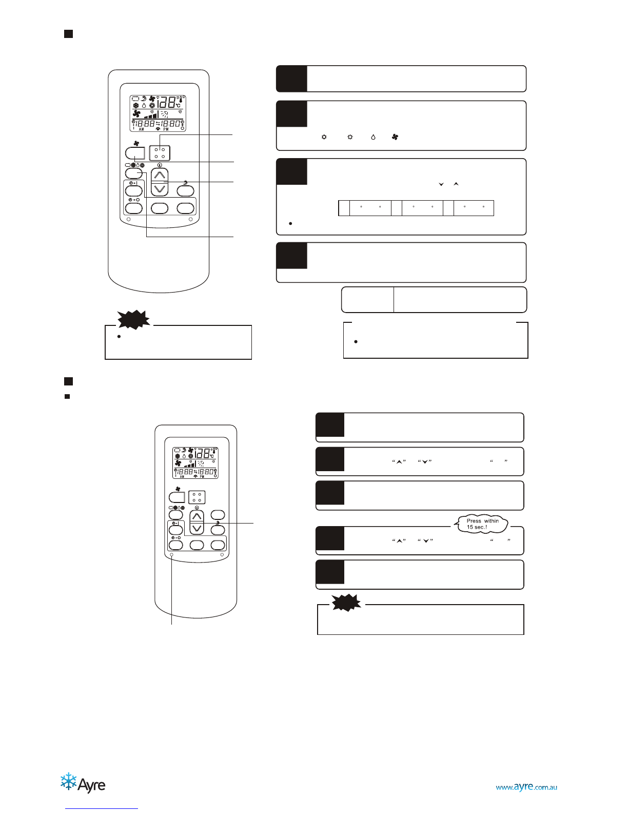
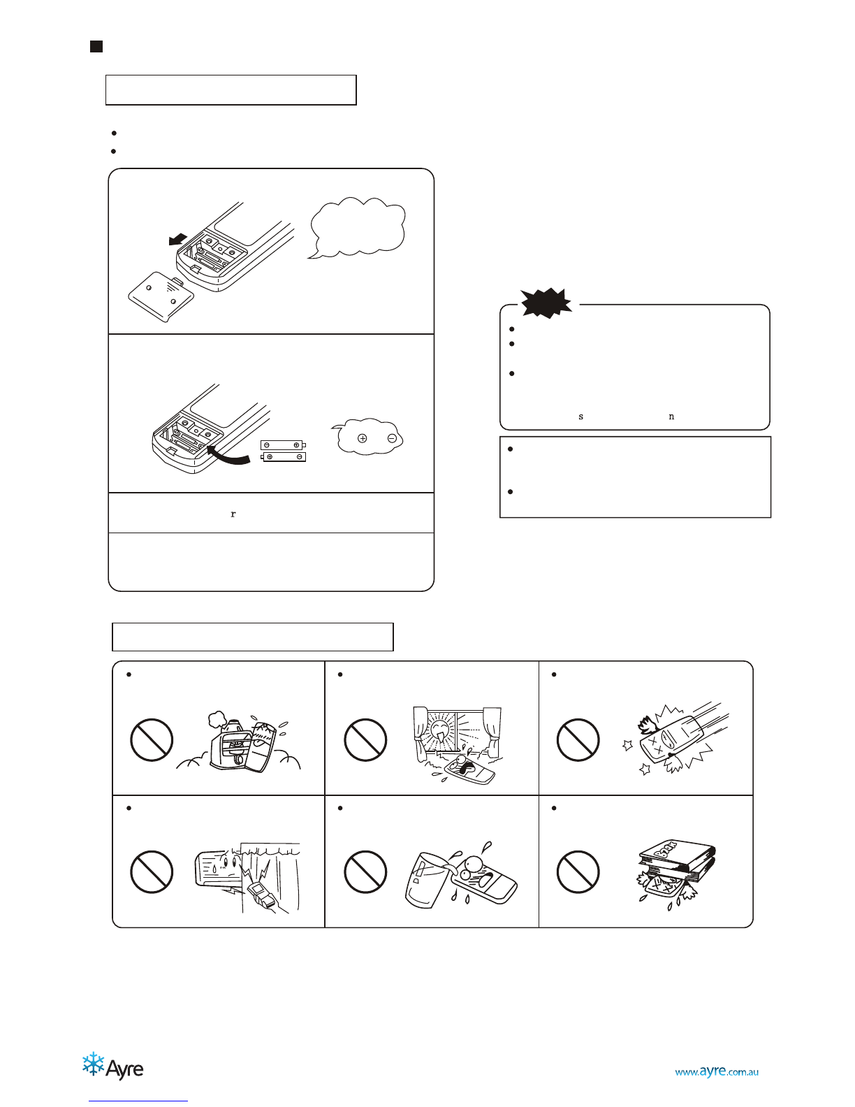
Features of Protector
Feature of HEATING mode
Preheat
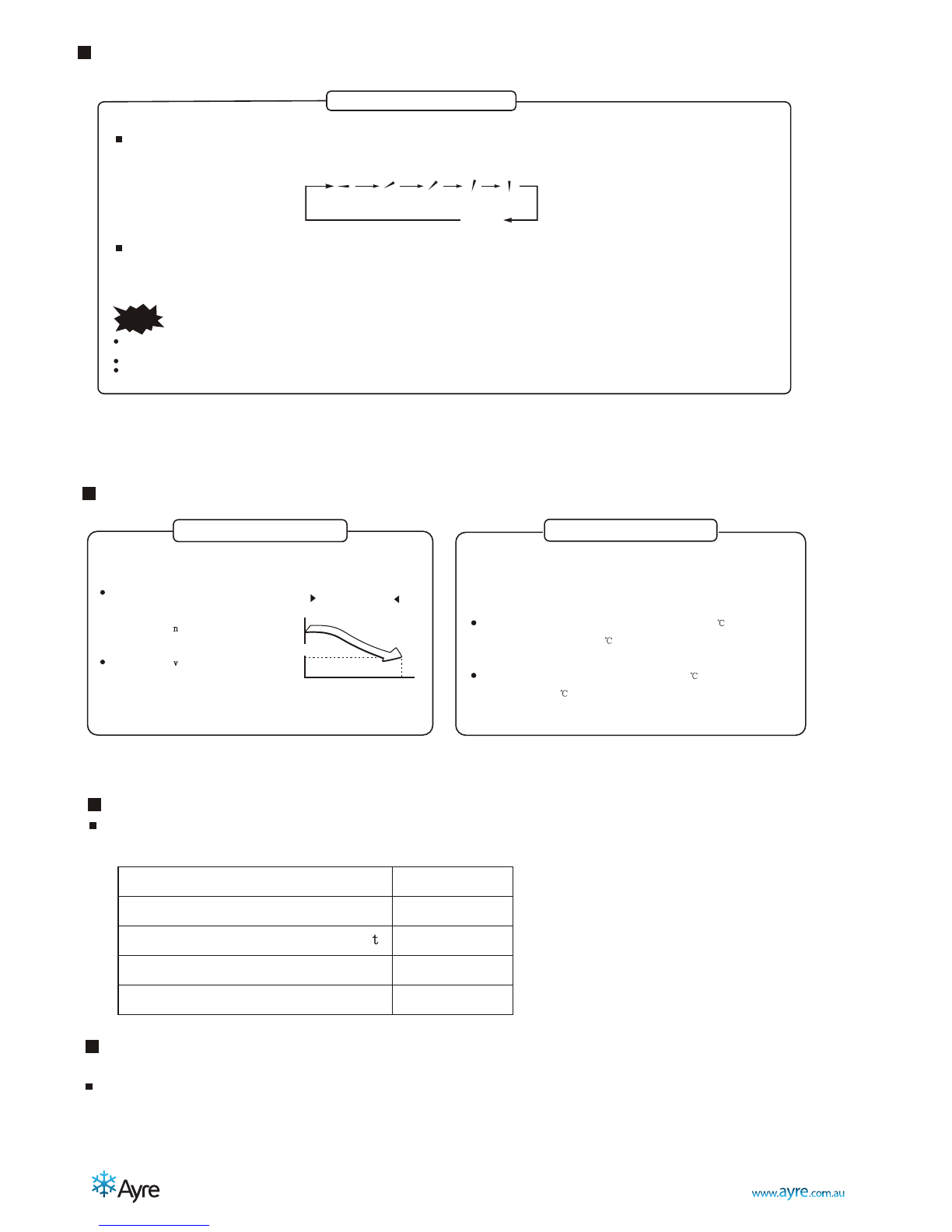
DRY Room temperature is below 18
If the air conditioner runs for a long time in
"COOLING" or "DRY" mode at air relative
humidity higher than 80% (doors or windows
opened),dew may generate and drip near air outlet.
The protective device will trip at
following cases.
Stop the appliance and restart it at once
or change other modes during operation,
you have to wait 3 minutes before restarting.
After switching on the power circuit breaker
and then turn on the air conditioner at once,
you have to wait about 20 seconds.
In case all operations have stopped, you need
Press "ON/OFF" button again to restart it.
Set TIMER once again if it has been canceled.
Defrost
After a long time of operation, the air
conditioner should be inspected for
the following items.
Abnormal heating of the power supply
cord and plug or even a burnt smell.
Abnormal operating noise or vibration.
Water leakage from indoor unit.
Metal cabinet electrified .
Stop using the air conditioner if above
problem happened.
It is advisable that the air conditioner
should be given a detail check-up
after using for five years even if none
of the above happen.
Do not place any obstacles in front
of the outlet of the outdoor unit for
fear it affects operation and increases
the noise level.
2-5 minutes are necessary to preheat the indoor heat exchanger at the beginning of
"HEATING" operation, lest cold air be discharged.
In "HEATING" operation the appliance will defrost automatically. This procedure lasts
2 10 minutes, then returns to "HEATING" mode automatically. During defrosting, indoor
fan stop running and return to heating mode operation automatically when
defrosting has finished.
Inspection
Noise pollution
Operating condition
The protective device maybe trip and stop
the unit within temp range listed below:
HEATING
Outdoor air temperature is over 21
COOLING
Outdoor air temperature is below -7
Room temperature is over 31
Outdoor air temperature is over 43
Room temperature is below 17
Install the air conditioner in a place
that can bear its weight in order to
operate more quietly.
Install the outdoor unit in a place
where the air discharged and the
operation noise do not annoy your
neighbors.
2
User manual • T-series Ducted Air Conditioner

The air conditioner cannot be started up until it is powered on for 2 hours. Furthermore, in
case of a shutdown lasting for about one diel only, please do not cut off the electricity supply. (it
is necessary to heat the crankcase heater so as to avoid force start of compressor. )
Notice that the air inlet/outlet must not be choked up. If chokeup takes place, the air
conditioner behavior may be affected, or air conditioner cannot run because of actuation of
protector.
After you have installed the wire controller, the function of auto-restarted is shielded by wire
controller.
Requirements
3
PARTS AND FUNCTIONS
Drain pipe
1
2
3
4
5
6
7
8
9
13
12
11
10
2
1
10
4
5
6
2
8
9
3
7
Outdoor unit
Drain pan
Refrigerant pipe
Centrifugal fan motor
Drain adapter
Air outlet
Electric control box
Remote controller
Line control panel
(Selected and purchasedadditionally )
Refrigerant connecting pipe
Connecting cable
Stop valve
Air-outlet grill enclosure
Inlet air
Inlet air
Outlet air
SLEEP
SLEEP
FAN
FAN
TIMER
TIMER
SWING
SWING
ON/OFF
ON/OFF
MODE
MODE
MID
MID
SWING
SWING
AUTO
AUTO
DRY
DRY
FAN
FAN
HEAT
HEAT
COOL
COOL
FEEL
FEEL
SLEEP
SLEEP
TIMER ON
TIMERON
HIGH
HIGH
LOW
LOW
TMIEROFF
TMIEROFF
User manual • T-series Ducted Air Conditioner

4
Parts of Names & Functions
During normal operation time......time only is indica
t
ON/OFF button
This button,when pressed,starts
operation and stops when repressed.
SLEEP button
This button changes SLEEP operation.
This button sets the temprature and time.
SET button
TIMER button
The button selects ON TIMER
operation or normal operation.
FAN SPEED button
Button for setting the air quantity
Symbols indicate OPERATION MODE
Indicators for the operation which
has been set.
OPERATION MODE select button
Each time the button is pushed,the
indicator is switched over in turn.
Temperature indicator
Indicates the set temperature.(It doesn't indicate
temperature when operation mode is at AUTO)
AIR FLOW indicator
Indicators selected flap mode.
Air flow indicator
Indicators the seleted air flow rate.
Present time and ON-TIMER indicator
During ON-TIMER operation......[ START] is indicated
Temperature indicator
Indicates the set temperature.(It doesn't indicate
temperature when operation mode is at AUTO)
CLOCK button
RESET button
ON/OFF
CLOCK RESET
HR. MIN.
REMOTE CONTROLLER OPERATION
User manual • T-series Ducted Air Conditioner

5
AUTO mode operation procedure
Operates by selecting automatically the operation mode(HEAT,DRY,COOL)depending on the room temperature at starting.
With the remote controller pointing toward the air conditioner.
Press the ON/OFF button.
1
When the unit is not at AUTO mode:
2
Press the MODE select button.
Move the MODE to the (AUTO)position.
To Stop: Press the ON/OFF button.
The operation of the AUTO
mode can be performed by
only pressing the ON/OFF
button from the next time.
Air is not blown out during opera-
tion.
NOTE
If you don't like the content of AUTO mode operation,
change to HEAT,DRY or COOL than AUTO.
If you don't like the content of AUTO mode operation,
change to HEAT,DRY or COOL than AUTO.
Temperature adjusting procedure during AUTO operation
Air temperature adjustment is possible even during automatic operation.There are 6 levels of adjustment possible with
the button or the button .
ON/OFF
CLOCK RESET
HR. MIN.
2
1
Press the or button.
1
In AUTO mode,the indicator default temperature is 24 .
When the button or the button is pushed ,the indicator does not change.
When a change in temperature is desired
TOO COOL
Press the button.
TOO HOT
Press the button.
ON/OFF
CLOCK RESET
HR. MIN.
User manual • T-series Ducted Air Conditioner

6
COOL/ HEAT / DRY mode operation procedure
With the remote controller pointing toward the air conditioner.
Press the ON/OFF button.
1
3
Press the MODE select button.
Move the MODE to the desirable operation position.
[ (COOL), (HEAT), (DRY), (FAN) ]
[ (COOL), (HEAT), (DRY), (FAN) ]
2
4
Set to your favorite temperature press or button.
Standard.
Set to your favorite temperature press or button.
Standard.
Press the TEMP . button.
If FAN is selected,room temperature isn't controlled,operation being continuously.
26 C ~28 C
HEAT
22 C ~24 C
COOL
DRY
21 C ~24 C
NOTE
Press the FAN SPEED button.
Set to your favorite air flow rate.
To Stop: Press the ON/OFF button.
Air is not blown out at during operation.
Changing procedure of the content of the operation
Set to the new content.
The content of the operation can be set or changed
even while the air conditioner is off operation.
The content of the operation can be set orchanged
even while the air conditioner is off operation.
When cells are inserted,the present time is automatically set to AM12:00
Ex:Set to AM10:30.
Ex:Set to AM10:30.
1
Please slide and remove the cover.
Press the CLOCK switch,with the tip of a ball pen, etc,
the present time can be set.
3
Press the CLOCK switch again.
NOTE
The timer is set on the basis of the present time.So set the
present time correctly.
The timer is set on the basis of the present time.Soset the
present time correctly.
ON/OFF
CLOCK RESET
HR. MIN.
1 ,3,5
2,4
2
Press the or button to set the HR .
4
Press the or button to set the MIN .
5
Press the clock switch to confirm.
2
1
4
3
ON/OFF
CLOCK RESET
HR. MIN.
Present time setting procedure
User manual • T-series Ducted Air Conditioner

Air flow direction adjustment procedure(Some type remote controller has no this function)
Up/down direction can be adjusted by using the AIRFLOW button on the remote controller.
This button,each time pressed,changes the mode in the following sequence:
Up/down direction can be adjusted byusing the AIRFLOW button on the remote controller.
This button,each time pressed,changes the mode in the following sequence:
Adjusting air flow direction
NOTE
When the room temperature controller(thermostat)trips in the heating mode or when the defrosting operation is conducted,the blow flap changes automatically to the
horizontal position.
When the heating operation has just started and the room temperature is still low,it may take a little time before the flap moves to the above sway operation angle.
The flap may stop at the tilted down-blow position during the"Sway operation"in the heating mode,
AUTO
push the LOUVER button,changes the mode to swing louver.
Push the button,to stop swing.
push the LOUVER button,changes the mode to swing louver.
Push the button,to stop swing.
About TIMER operation
About Amenity reservation
Amenity reservation function is provided to start the operation a little earlier
so that the room temperature is near the optimum temperature at the timer ON
time in case of starting the operation by TIMER ON/OFF.
Mechanism
Mechanism
Checking of the room temperature
starts 60 minutes ahead of the timer
starts 60 minutes ahead of thetimer
ON time.Depe ding on the tempera-
ture at that time,operation starts 5 to
60 minutes ahead of the timer ON time.
Amenity reser ation is the function
only for COOL and HEAT operation
mode (including AUTO).It does not
actuate in DRY mode.
About SLEEP Operation
When the SLEEP operation is selected,the room temperature is auto-
matically controlled with elapsed time so that the room isn't too cool
during cooling or too warm during heating.
During cooling and dry:Present temperature is raised 1 in an hour
(when the timer is set),and 2 raise in two hours.Then the temperature
dosen't change ever.
During heating:Present temperature is lowered 1 in an hour (when the
timer is set),and 2 lower in two hours.Then the temperature dosen't
change ever.
In cool operation
In cool operation
Set
Temperature
Set
Temperature
Check the room
temp. 60 min
ahead
Check the room
temp. 60 min
ahead
Set time
Set time
(Operation)
(Operation)
(Stop) Operation starts
About FAN SPEED
Capacity of the air conditioner can be selected by your choice during heating or cooling.
Operation capacity by your choice
Set automatically by microcomputer
Powerful operation with high capaci y
Standard operation
Standard operation
Optional
Optional
FAN SPEED
FAN SPEED
AUTO
AUTO
HI
MED
MED
LO
LO
About power-off memory function
When the airconditioner disconnect the power supply suddenly, restart it , then theair conditioner operates at the mode
it did beforepower suddenly failed.
7
User manual • T-series Ducted Air Conditioner

Remote controller handling procedure
Batteries replacing procedure
Following cases signify dead cells.Replace the dead batteries with new ones.
Receiving sound is not emitted from the unit when signal is transmitted.
Indicator becomes indistinct.
Receiving sound is not emitted from the unit when signal is transmitted.
Indicator becomes indistinct.
Please slide and remove the cover.
Exchange the batteries.
Install the cove .
Install the cove .
Set it to the present time.
Guideline of the life time is printed on the battery.
The battery life may be shorter than that of the air
conditioner depending on the date of manufacture.
However,the battery may be alive even after the
nominal life time expired.
NOTE
Do not use an old battery together with a new one.
Remove cells when the remote controller is not
used for a long period.
The life of a cell made in conformity to JIS or IEC
Is 6 to 12 months in normal use.If it is used longer
or an unspecified cell is used,a liquid leaks from
the cell,cau ing the remote co troller inoperative.
1
2
3
4
Attention to
the and
marks.
Attention to
the and
marks.
Slide the cover
upwardly in the
direction of the
arrow.
Slide the cover
upwardly in the
direction of the
arrow.
Note of remote controller handling
A place wlth high temperature such
as near an electric carpet or a stove.
A place unprotected from direct
sunlight or strong lighting.
It will be damaged if falling.Be careful.
Do not put obstacles between the
remote controller and the unit.
Protect the remote controller from
being splashed with water,etc.
Do not put weights on the remote
controller.
8
User manual • T-series Ducted Air Conditioner

TROUBLES AND CAUSES ABOUT REMOTE CONTROLLER
Before you ask for service or repairs, check the following points.
Setting change is impossible.
Symptoms Causes Reason and Disposal
The fan speed can not be
changed.
Check whether the MODE
indicated on the display is
AUTO.
Check whether the MODE
indicated on the display is
DRY.
When the automatic mode is
selected ,the air conditioner
automatically selects the fan
speed .
When dry operation is selected,
the air conditioner automatically
select the fan speed .The fan speed
can be selected during
and FAN ONLY,and HEAT.
COOL
The Transmission lndicator never comes on
Symptoms Causes Reason and Disposal
The remote control signal is
not transmitted even when
the ON/FF button is pushed.
Check whether the batteries
in the remote controller are
exhausted.
The remote control signal is
not transmitted,because the
power supply is off.
The Display never comes On
Symptoms Causes Reason
The TEMP.indicator does not
come on.
Check whether the MODE
indicated on the display is
FAN ONLY.
The temperature cannot be
set during fan only operation.
IMPORTANT SAFETY INFORMATION
CAUTION
!
Do not attempt to install this unit by yourself.This unit requires
installation by qualified persons.
DANGER
!
Do not attempt to service the unit yourself.This unit has no user
serviceable components.Opening or removing the cover will
expose you to dangerous voltage.Turning off the power supply will
not prevent potential electric shock.
DANGER
!
Never put hands or objects into the air outlet of indoor or outdoor
units.These units are installed with a fan running at high speed.
To touch the moving fan will cause serious injury.
DANGER
!
9
User manual • T-series Ducted Air Conditioner

Ventilate the room regularly while the air conditioner is in use,
especially if there is also a gas appliance in use in this room,
Failure to follow these directions may result in a loss of oxygen
in the room.
WARNING
!
To prevent electric shock,turn off the power or disconnect the
power supply plug before beginning any cleaning or other routine
maintenance.
WARNING
!
Do not use liquid cleaners or aerosol cleaners,use a soft and dry
cloth for cleaning the unit .To avoid electric shock,never attempt
to clean the units by sprinkling water.
CAUTION
!
Do not use caustic household drain cleaners in the unit.Drain
cleaners can quickly destroy the unit components(drain pan and
heat exchanger coil etc).
NOTE
!
For proper performance,operate the unit in temperature and
humidity ranges indicated in this owner s manual.lf the unit is
operated beyond these conditions,it may cause malfunctions
of the unit or dew dripping from the unit.
10
WARNING
!
DANGER
!
To avoid the risk of serious electrical shock.Never sprinkle or
spill water or liquids on unit.
CAUTION
!
These are not failures
Room air is smelly.
A bad odor comes from the air conditioner.
Smells impregnated in the wall,carpet,furniture,clothing,or furs,are coming out. A white mist
of chilled air or water is generated from the outdoor unit.
If any of the following conditions occur,stop the air conditioner immediately,set off the power
switch, and contact the dealer.
The indicator lamps flash rapidly(five times per second),you disconnect the unit with the
power and then connect the unit with the power again after two or three minutes but the
lamps still flash.
Switch operations are erratic.
The fuse is blown frequently or the circuit breaker is tripped frequently.
Foreign matter or water has fallen inside the air conditioner.
Any other unusual condition is observed.
User manual • T-series Ducted Air Conditioner

User guideline
Precautions
The air conditioner must be correctly installed by installation technicians according to the attached Installation Manual , and the user himself should not install it.
Pre-installation precautions
Please confirm thatthe installation personnel are qualified in relevant installation service.If the airconditioner was installed by persons
without special skills,normal operations would not be ensured, even the personaland estate safetywould be affected
How to install indoor unit
The user's installation site should be provided with regular power supply in conformity with that indicated in nameplate of the air conditioner, and its voltage should be within a range 90
% 110 % of the rated voltage value.
Power circuit should be equipped with protector, such as electricity leakage protector or air switch, which should possess a capacity greater than 1.5 times the maximum current value
of the air conditioner.
Never fail to adopt personal circuit and effectively-grounded socket compatible with the attached plug of the air conditioner. The attached plug is equipped with grounding pin, and it
must not be modified as desired.
Please adopt the fuse or circuit breaker prescribed in Installation Instructions.
Only qualified electrician is allowed to carry out wiring tasks strictly according to electric safety requirements.
Do ensure good earth of air conditioner, in other words, the main power switch of air conditioner must be connected to reliable ground wire
The air conditionershould be installedsecurely; otherwise poorinstallation may leadto abnormal noisesand vibration.
Outdoor unit should beinstalled at a spotensuring that its airoutlet noises and hotexhaust will not violateyour neighbors.
INDOOR UNIT INSTALLATION
Installation method forindoor unit
1.Pendant installation of indoor unit
Installation mode of indoor unit must ensure minimum length of system pipeline and air conduit, therefore the Indoor unit should be installed at medium position of a suite.
Ensure adequate strength of the top suspension rod so as to withstand weight of the unit. Determine the position of suspension rod, align it to pendant-mounting hole in the unit, and then
tighten it (for position of suspension rod, see outline dimensional drawing for the unit)
Check the installation levelness of the unit, and set the drainage slope according to dimensions listed in figure below (Gradient greater than 1/100)
11
User manual • T-series Ducted Air Conditioner

2. How to mount outlet pipe
Generally, we have two types of outlet pipe available, i.e. rectangular or round ones.
Rectangular air conduit can be directly connected to air outlet of indoor unit by rivets. For outlet dimensions, see outline drawing of the unit.
Round air conduit should be connected to a piece of transitional air conduit before it is connected to air outlet of indoor unit, the other end of it can be separately connected to air conduit
window or connected to air conduit window after air flow diversion, and the total length should not be over 6m. As shown in figure below, air speeds at all air outlets should be set to basically
consistent so as to meet the room air-conditioning requirements.
Indoor unit
Air-outlet window
Outlet pipe
Transitional air
conduit
Air inlet
3. Installation method for return air pipe
In case sidewise air intake is adopted, return air pipe should be fabricated and rivet-connected to return air orifice, and the other end of it
should be connected to return air window.
In case of underside air intake, purchase or fabricate a section of pleated canvas air conduit serving as transition joint for return air orifice and
return air window. in this way, it can be freely adjusted according to height of indoor ceiling board; in addition, during operation of the unit , canvas
air conduit may avoid vibration of ceiling board, as shown in figure below.
Installation mode for sidewise air intake
Unit
Canvas air conduit
Return air pipe
Installation mode for underside air intake
Return air window
Rivet
Unit
Suspension rod Unit
Return air pipe
Canvas air conduit
Transitional air conduit
Outlet pipe
Air-out window
4. Tips for installation of return air pipe and outlet pipe
To minimize energy loss occurring in transmission process and condensed water during heating operation, return air pipe and outlet pipe should
be equipped with heat-insulating layer as shown in the figure.
Return air pipe and outlet pipe should be fixed to floor precast slabs by iron stand; in addition, all ports of the air conduit should be tightly sealed
by gasket cement, and it is advisable that the edge clearance of return air pipe should be 150mm at least.
Drain pipe for condensed water should be installed with minimum gradient of 1 , and the drain pipe should be insulated with heat-preserving
pipe casing as well.
Air conditioner
Air conditioner
Plastic pin
Plastic pin
Heat preserving
wool
Heat preserving
wool
Tin foil
Tin foil
Plastic pin cap
Plastic pin cap
Return air pipe
Canvas air conduit
Installation diagram for indoorunit
Rivet
Return air window
including filter screen
12
User manual • T-series Ducted Air Conditioner

Dimension
(1)The relationship betweenthe ceiling opening of indoor unitand the location of hanging bolts.
1096
1200
1243
221.8
380 550
590
640
(2)Install hanging bolts
If the ceilinghave been builded,please use anchor bolts .
For the newly-builtceiling , please use embedded fixed
plate embedded anchor bolts or other locallypurchased
parts to reinforce the ceiling , ensure that it is hard
enough to support the weight ofthe indoor unit.
850
(Air inlet:1096 310)
13
Indoor unit
Hanging bolt
Long nut
Anchor bolt
Ceiling
User manual • T-series Ducted Air Conditioner

Location for installing outdoor unit
1. Install it at a place where it is convenient for installation and
well ventilated.
2. Keep the required distance away from the wall as reqiured on
the previous page when carrying on installation.
3. Pipe length and drop height should comply with the
scope required below.
4. When operating at a special place, for example, a place
of greasy dirt, vulcanization gas or high-salty seashore,
make sure to adopt an effective isolation measure.
5. Avoid installing it on the roadside where there is a risk
of muddy water.
6. Install it where your neighbors would not be annoyed by
operating noise or discharged hot air.
7. Install it on a fixed shelf that is not subject to increasing noise.
8. Install it at a place without blockage for air outlet.
Outdoor unit
Indoor unit
elbow to
prevent water
from entering room
LthgiehpordxaM
25m
10m
5
OUTDOOR UNIT INSTALLATION
Please install the air conditioner according to international rules.
Above figures are only a simple presentation of the unit, it may not match the external appearance of the unit you purchased.
Over 100mm
Over 1500mm
Over 200mm
Over 500mm
Over 100mm
Max pipe length
Max drop height L
Max. bending No.
Air inlet
Air inlet
Air inlet
Air inlet
Air outlet
Air outlet
12kW, 15kW
950
373
340
416
Model: 15kW
940
376
340
400
600
608
Sketch of installation as following:
Model: 12kW
1
User manual • T-series Ducted Air Conditioner

Leaked refrigerant will generate poisonous gas if meeting fire.
Allowed Length and Drop of Pipes
Material and Size of the Pipes
Requirements are different when installing the outdoor unit.
Three length (3m,5m,10m) of pipes are available to purchase.
Pipe external
diameter
Added wrench torque
9.52
15.88
32.7(3.33kgf.m) ~
61.8(6.3kgf.m)~75.4(7.7kgf.m)
Connection of the Refrigerant Pipe
Double-span should be used when connecting the pipes.
The wrench torque follow the below table:
39.9(4.07kgf.m)
(N.m)
Wrap the connecting pipes and cables together with tape,
but not including the drainage pipe. Drainage pipe can be
fixed along them separately.
Wrapping from the joint of outdoor unit to that of indoor unit,
each round of tape should cover half of its previous one.
Wrap the piping
!
CAUTION
REFRIGERANT PIPE INSTALLATION
Ventilate the air if there was any refrigerant leakage during the installation.
Make sure there is no refrigerant leakage after the installation.
Leaked refrigerant will generate poisonous gas if meeting fire.
Pipe external
diameter
Added wrench torque
12.7
19.05
49.5(5.04kgf.m) ~
97.2(9.9kgf.m)~118.6(12.1kgf.m)
60.3(6.16kgf.m)
(N.m)
Connecting pipes
Cables
Drainage pipe
14.2(1.4kgf.m)~17.0 1.7kgf.m
Copper Pipe for Air ConditionerPipe Material
Size(mm)
Gas side
Liquid side
Model N:N:
12.7(1/2inch)
19.05(3/4inch)
15
Liquid pipe diameter
Additional charge for 1m pipe(R410A)
The additional charge is base on the diameter and length of outlet/inlet liquid type .
This AC has been charged with that for 5m pipe, those beyond 5 m should recharge as follows.
1/4
0.022kg 0.054kg
3/8
1/2
0.110Kg
Additional refrigerant charge
User manual • T-series Ducted Air Conditioner

16
The drain pipe of indoor unit must have the heat insulation , or it will condense dew, as well
as the connections of the indoor unit.
The declivity of the drain pipe downwards should not be over 1/100, and no winding and bending.
The total length of the drain pipe when pulled out traversely shall not exceed 20m , when the
pipe is over long, a prop stand must be installed every 1.5 to 2m to prevent winding.
Refer to the following figures about the installation of the pipes.
Do not impose any pressure on the connection part of the drainage pipe.
Be sure to follow this Installation Manual during drainage installation,
the drainage pipe must have the heat insulation to prevent condensing.
CAUTION
DRAINAGE PIPE INSTALLATION
Drainage Pipe Material, Heat-insulating Material
Polyvinyl chloride pipe ( 32mm outer diameter)
Foamed polyethylene insulation plate (10mm thickness)
The listed material should be used:
Drainage Pipe
Material
Heat Insulation
Material
VP30
Support Bend
Up and Down
Fold
As long as possible about (10mm)
Lean Downward
over 1/100
1.5m~2m
Lean Downward over 1/100
Connection Procedure
Connect the transparent pipe with the polyvinyl chloride pipe.
Use polyvinyl chloride glue at the connection part of the drainage pipe, be sure no water
leakage.
Paste glue at the front 40mm of the polyvinyl chloride pipe, insert it into the transparent pipe.
It needs 10 minutes for the glue to dry. Do not impose pressure on the connection during the
drying period.
Heat Insulation
Wrap the flexible hose carefully with the attached heat insulation material from the start to the
end (to indoor part) Flexible Hose Hose band
Attached Heat-insulation
Material
Polyvinyl Chloride Pipe
Field-arranged
Heat-insulation
Material
User manual • T-series Ducted Air Conditioner

!WARNING
Specified power cables should be used. Do not apply any pressure on the
terminals used to connect.
Grounding must be properly done.
Improper connection may cause fire.
Electric Wiring must be done by professionals. Use a separate circuit according
to national regulations.
The temperature of refrigerant circuit will be hight ,please keep the interconnection
able away from the copper tube.
If the wiring capacity is not enough, electric shock or fire may occur.
If the supply cord is damaged, it must be replaced by the manufacturer or its service agent
or a similarly qualified person in order to avoid a hazard.
An all-pole disconnection switch having a contact separation of at least 3mm in all poles sho-
uld beconnected in fixed wiring.
The grounding wire should be away from gas pipes, water pipes, telephone,
lightening rods or other grounding wires. Improper grounding may cause electric
shock.
Be sure to Install Current Leakage Protection Switch. Or electric shock may occur.
CAUTION
ELECTRIC WIRING
Power cord is to be selected according to national regulations.
Outdoor unit power cord should be selected and connected according to the outdoor unit
installation manual.
Wiring should be away from high temperature components, or the insulation layer of the
wires may melt down.
Use wire clamp to fix the wires and terminal block after connection.
Control wire should be wrapped together with heat insulated refrigerant pipes.
Connect the indoor unit to power only after the refrigerant has been vacuumed.
Don t connect the power wire to the signal wire connection end.
17
User manual • T-series Ducted Air Conditioner

1. Power cord indicates the supply cable from indoor air switch to indoor unit or outdoor unit.
Indoor/outdoor power connecting wire indicates the supply cable connecting indoor unit and o utdo or unit .
2. Cross-section area of power cord wire is the minimum value here. In case power-connecting wire is longer than usual, just
select the conductor cross-section a level higher than the specified one to avoid voltage drop.
4. In case single-core double-layer wire is adopted, its cross section should be one level bigger than the specified one, and the wire
should be covered with dedicated electric sheath.
2
3. The cross section of ground wire for the whole set of air conditioner should be 2 mm at least.
Power cord connected to indoor unit should be cable RVV (300 500); the power cord connected to outdoor unit and the
indoor/outdoor power connecting wire should be multi-wire strand cable ( neoprene ) YZW (300 500V).
Notice: Drain pipe must not be flattened during binding treatment.
Drain pipe outlet should be led to a
place that can avoid affecting the
environment.
Liquid pipe
Liquid-pipe heat preservation
Drain pipe
Heavy-current cable
Gas-pipe heat pre ser vat ion
Gas pipe
Light current cable
1. Wiring method for indoor unit: Open the electric
junction box to carry out wire connection. Notice
that the connecting wire should be passed through
wire-inlet rubber ring of the box. Connect the wires
according to stipulations in the wiring diagram, and
the wire splices at connecting terminal should be
tightly compacted, free of looseness.
2. Binding treatment
Once the connecting wires have been properly connected, bind the connecting tubing, connecting wire and drain
pipe by binding tapes
After binding treatment, the cross section is shown in the figure below:
Notice
18
User manual • T-series Ducted Air Conditioner
Other manuals for T-series
1
This manual suits for next models
2
Table of contents
Other Ayre Air Conditioner manuals
Popular Air Conditioner manuals by other brands

Mitsubishi Electric
Mitsubishi Electric Mr.SLIM MS24WN Service manual

Mitsubishi Electric
Mitsubishi Electric PUZ-ZM200YKA2-ET Service manual

Johnson Controls
Johnson Controls York VIR 40A installation instructions

Airxcel
Airxcel Marvair ComPac II AVHDA90 Installation & operation manual

Frigidaire
Frigidaire LRA257ST216 installation instructions

Haier
Haier AU362XHERA installation manual