Ignition6 V -29/5W.
Validfor:20
mph.
enginestonr.772302
25mph.enginestonr.
779301
30mph.enginestonr.780501
Theignitionissupplied
with:
1Coil29W.fortheheadlight
1Coil5 W.foradditionalchargingofthe
battery
1H.T.coil
Allthesecoilsaremountedonthebaseplate,placedin
theflywheel.
Whendismountingtheflywheelitmustbesecuredby
tool
nr.48.50.10.
Afterremovingthenut,theflywheelcanbepulledoff
withtoolnr.48.50.02securedagainwithtoolnr.
48.50.10.
Alwaysputtheflywheelwiththeopensideupwardson
theworkbenchtopreventironparts,likesmallwashers,
tobeattractedbythemagnetos.
Loosenthe3 screwsofthebaseplateandremovethe
baseplateoutofitspositioninthecrankcase.
Inordertomovethewiresfreelythroughtherubber
grommets,oilthema littlebefore.
Neverpullthebaseplatetomovethewiresoutofthe
grommetsbutalwayspullthewiresthemselves.
Mountingtheignitionthewireshavetobeputintothe
grommetsfirst.Someoilonthewiresmakesiteasier.
Fitthebaseplateintothecrankcaselocation,between
thecams.Takecarethatthisisdonecorrectlyandthat
nowireispinchedbetweenbaseplateandcasting.
Fitthe3 screwsbutdoenotyettightenthem.
Nextmounttheflywheelandmakesurethatthekeyfits
inthekeygrooveoftheflywheel.Fitplainwasher,
toothedwasherandnutonthecrankshaft.
Securetheflywheelagainwithtoolnr.48.50.10and
tightenthenut.
Nowturntheflywheelclockwiseuntilthebreakergapis
maximum,visiblethroughtheholesintheflywheel.
Checkthebreakergap.
Thegapmustbebetween.35and.45mm.(.014and
.018").
Ifthegapisnotcorrectitcanbeadjustedbyloosening
thescrewofthebreakerpointset,andmovingthefixed
contactintothedesireddirectionbymeansofa screw
driver.
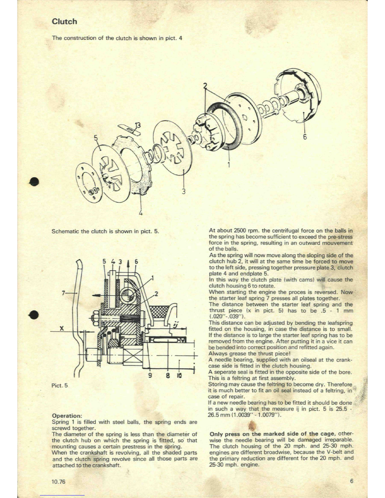
Forthecapacityofthesparktherupturedistance(see
pict.8 distanceA)isveryimportant.
/
:
\
Pict.8
Thisdistance
has
to
be
7-11
mm.
(.28.39").
Thisisanindicationforsuchpositionoftheflywheel
wherethemagneticfieldchangesitsdirection:a position
inwhichtheelectriccurrentismaximum.
Therupturedistancecanonlybechangedbychanging
thebreakergap.
Alargerbreakergapwillgivea smallerrupturedistance,
ashorterbreakergapmeansa largerrupturedistance.
Allpartsaremachinedinsuchanaccuratewaythatthis
rupturedistanceisautomaticallyiscorrectwhenthe
breakerpointgapiscorrectlyadjusted.
Theproceedingsmentionedbeforeguaranteemaximum
spark.
Nowtakecaretohavethismaximumsparkattheright
positionofthepistoninthecylinder,whichis1.8-
2.2.
mm.
(.071"
- .087")before
T.D.C.
Toadjustthis,screwa dialgaugeintothesparkplughole
ofthecylinderhead.
TurntheflywheelclockwiseuntilpistonisatT.D.C,
whichisthepointwherethedialpointerchangesits
direction.
Nowconnectanignitionadjustingapparatus,onewire
grounded(forinstanceoncylinderhead)theotheroneto
thecut-offwire
ofrthe
ignition(blackwire).
Aslongasthebreakerpointsareclosedthelampofthe
adjusterwillburn.
Turntheflywheelanti-clockwise.Themomentthe
breaker
pointsopenthelampwillextinguishbecauseof
theinteruptionoftheelectriccircuit.
Watchthedialgaugetoseehowfarthepistonhas
descended.
Whenthelatterislessthan1.8mm.
(.071")
thespark
betweenthesparkplugelectrodesistoolateorinother
wordstheignitionisretarded.
Inthatcasethebaseplatehastobeturnedanticlock-
wise.
Whenthedescendingofthepistoninthecylinderatthe
momentofignition,ismorethan2.2mm.
(.087")
the
sparkistooearly,orinotherwordstheignitionis
advanced.
Inthatcaseturnthebaseplateclockwise.
Thushavingadjustedthemomentofignition,thethree
baseplatescrewscanbetightened.
Insteadofusinga dialgaugea slidinggauge(vernier
calipers)canbeusedasfollows:
TurnthepistoninT.D.C.andmeasurethedistance
betweenpistonbottomanduppersideofthesparkplug
hole.
Turnbacktheflywheeltillthelampextinguishand
measurethedistanceagain.
Thedifferencebetweenbothsizesistheignition
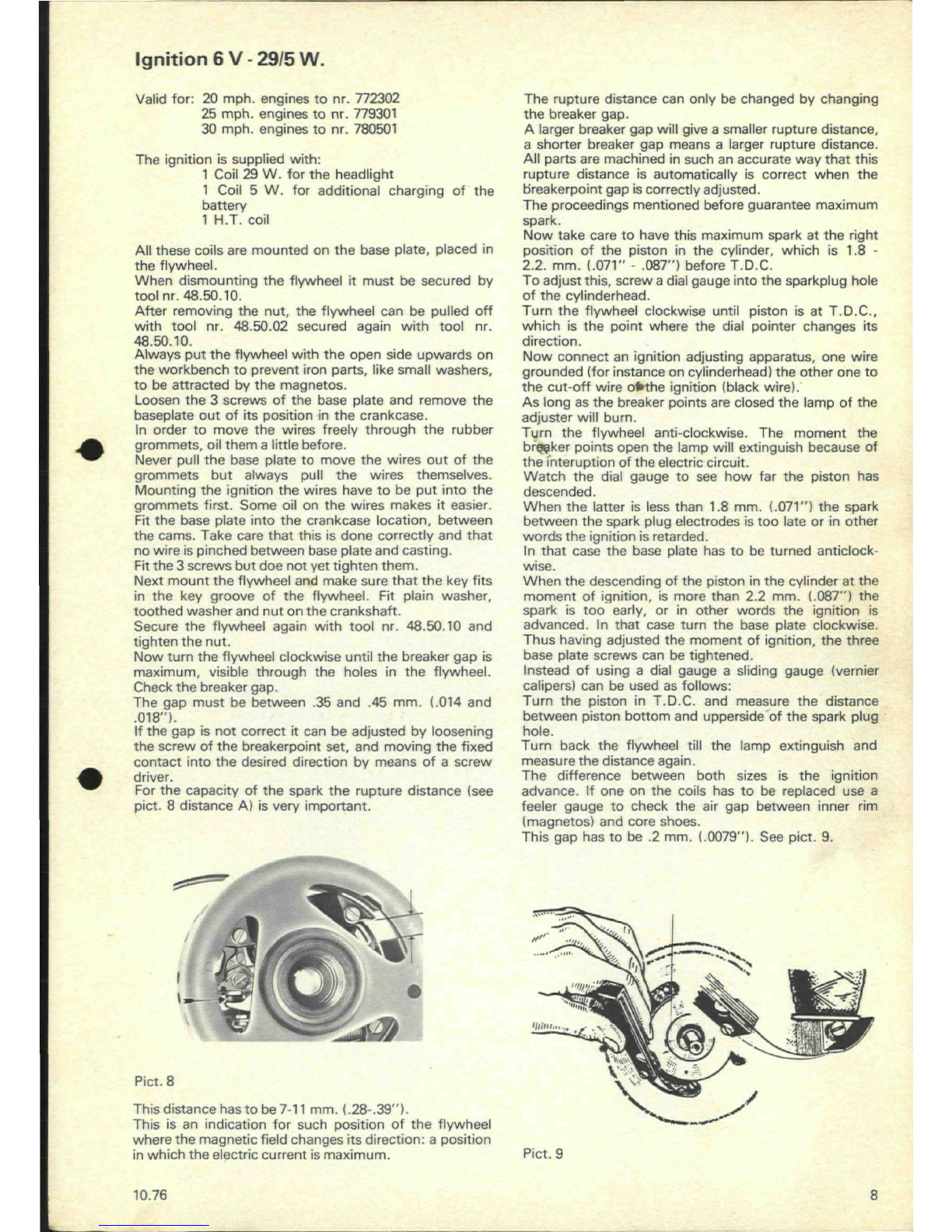
advance.Ifoneonthecoilshastobereplacedusea
feelergaugetochecktheairgapbetweeninnerrim
(magnetos)andcoreshoes.
Thisgaphastobe.2mm.(.0079").Seepict.9.
'
!> V>
•m
i
limn i
-v
s
s
Pict.9
10.76 8


 Supplementary service manual")


