Bavaria 42.598.82 User manual
Originalbetriebsanleitung
Schlagbohrmaschine
tOriginal operating instructions
Hammer Drill
pMode d’emploi d’origine
Perceuse électrique à percussion
CIstruzioni per l’uso originali
Trapano a percussione
lL Original betjeningsvejledning
Slagboremaskine
UOriginal-bruksanvisning
Slagborrmaskin
Bf Originalne upute za uporabu
Udarna bušilica
4Originalna uputstva za upotrebu
Električna glodalica za izradu utora
jOriginální návod k obsluze
Příklepová vrtačka
WOriginálny návod na obsluhu
Príklepová vŕtačka
Art.-Nr.: 42.598.82 I.-Nr.: 11013 BID 650/1
Anleitung_BID_650_1_SPK1__ 03.09.13 11:19 Seite 1

2
kUm eine Beschädigung des Getriebes zu vermeiden, darf der Bohren / Schlagbohren
Umschalter nur im Stillstand umgeschaltet werden
tTo avoid damaging the gearbox, the drill / hammer drill selector switch should only be
moved when the machine is at a standstill
pAfin dʼéviter dʼendommager lʼengrenage, il est uniquement possible de commuter
entre perçage et perçage à percussion à lʼarrêt.
CPer evitare danni al meccanismo, il selettore trapano / trapano a percussione può
essere azionato solo ad utensile fermo.
lL Omskifteren til boring/slagboring må kun betjenes, når maskinen står stille, for ikke at
beskadige gearet
UFör att undvika att maskinens växel förstörs, får du endast skifta på omkopplaren för
borrning / slagborrning medan maskinen står stilla.
Bf Da biste izbjegli oštećenje pogona, preklopnik za bušenje/udarno bušenje treba
aktivirati samo kad uređaj ne radi.
4Da biste izbegli oštećenje pogona, preklopnik za bušenje/udarno bušenje treba da
aktivirate samo dok uređaj ne radi.
jAby se zabránilo poškození převodovky, je třeba provádět přepínání vrtání/vrtání s
příklepem pouze ve vypnutém stavu.
WAby sa zabránilo poškodeniu prevodovky, smie sa prepínač vŕtania/príklepového
vŕtania prepínať iba vtedy, keď je vŕtačka v stave pokoja
Anleitung_BID_650_1_SPK1__ 03.09.13 11:19 Seite 2

3
1
2
2
13
6
5
8
74
1
3
8
8
Anleitung_BID_650_1_SPK1__ 03.09.13 11:19 Seite 3
4
4 5
6 7
8
4
6
1
5
7
3
BA
2
Anleitung_BID_650_1_SPK1__ 03.09.13 11:19 Seite 4

5
D
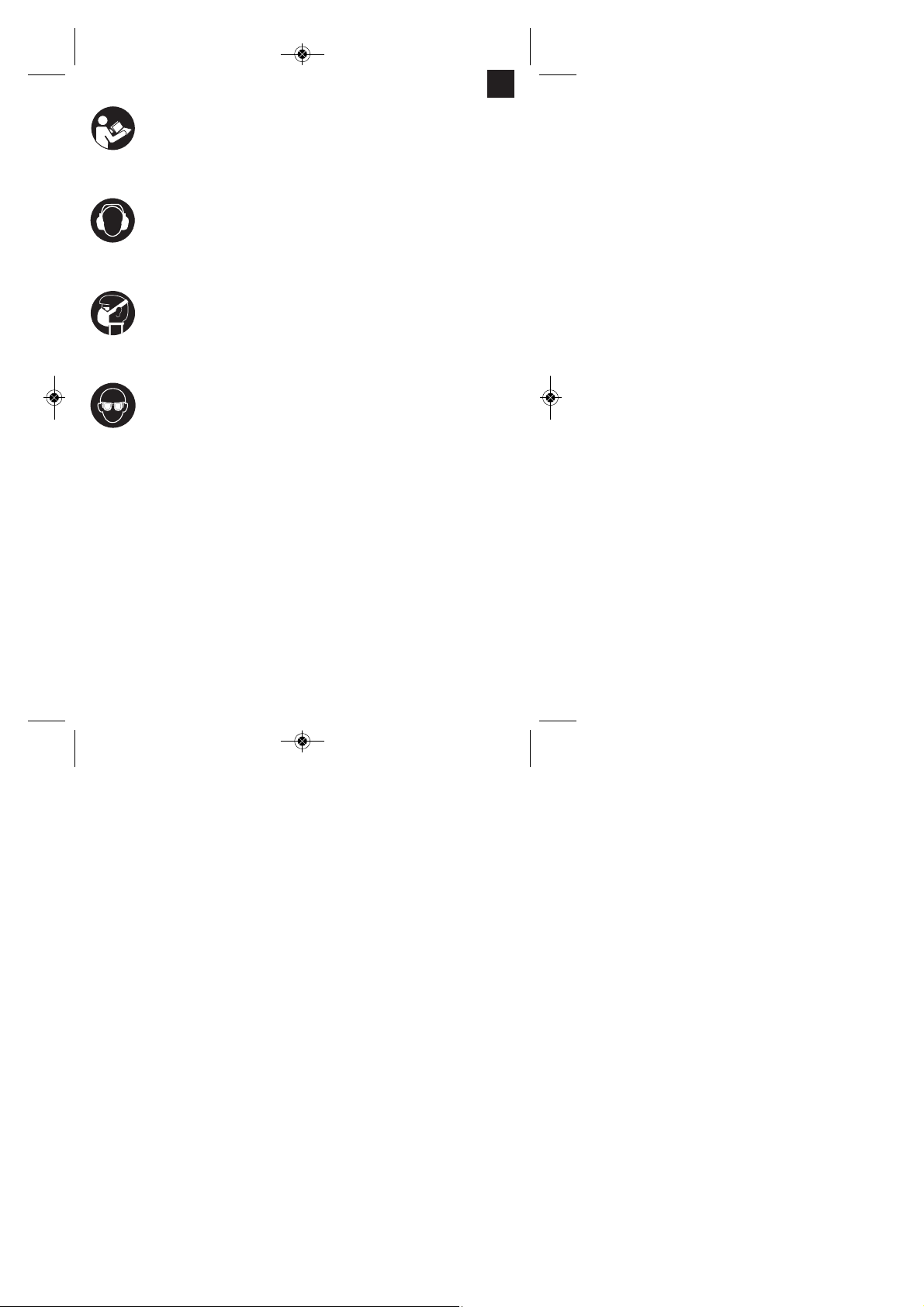
“WARNUNG - Zur Verringerung des Verletzungsrisikos Bedienungsanleitung lesen”
Tragen Sie einen Gehörschutz.
Die Einwirkung von Lärm kann Gehörverlust bewirken.
Tragen Sie eine Staubschutzmaske.
Beim Bearbeiten von Holz und anderer Materialien kann gesundheitsschädlicher Staub
entstehen. Asbesthaltiges Material darf nicht bearbeitet werden!
Tragen Sie eine Schutzbrille.
Während der Arbeit entstehende Funken oder aus dem Gerät heraustretende Splitter, Späne
und Stäube können Sichtverlust bewirken.
Anleitung_BID_650_1_SPK1__ 03.09.13 11:19 Seite 5

Achtung!
Beim Benutzen von Geräten müssen einige
Sicherheitsvorkehrungen eingehalten werden, um
Verletzungen und Schäden zu verhindern. Lesen Sie
diese Bedienungsanleitung / Sicherheitshinweise
deshalb sorgfältig durch. Bewahren Sie diese gut
auf, damit Ihnen die Informationen jederzeit zur
Verfügung stehen. Falls Sie das Gerät an andere
Personen übergeben sollten, händigen Sie diese
Bedienungsanleitung / Sicherheitshinweise bitte mit
aus. Wir übernehmen keine Haftung für Unfälle oder
Schäden, die durch Nichtbeachten dieser Anleitung
und den Sicherheitshinweisen entstehen.
1. Sicherheitshinweise
Die entsprechenden Sicherheitshinweise finden Sie
im beiliegenden Heftchen!
WARNUNG
Lesen Sie alle Sicherheitshinweise und
Anweisungen. Versäumnisse bei der Einhaltung der
Sicherheitshinweise und Anweisungen können
elektrischen Schlag, Brand und/oder schwere
Verletzungen verursachen zur Folge haben.
Bewahren Sie alle Sicherheitshinweise und
Anweisungen für die Zukunft auf.
2. Gerätebeschreibung (Bild 1)
1. Bohrfutter
2. Bohrtiefenanschlag
3. Bohren-/Schlagbohren-Umschalter
4. Feststellknopf
5. Ein-/Ausschalter
6. Drehzahl-Einstellring
7. Rechts-/Linkslauf-Umschalter
8. Zusatzhandgriff
3. Lieferumfang
nÖffnen Sie die Verpackung und nehmen Sie das
Gerät vorsichtig aus der Verpackung.
nEntfernen Sie das Verpackungsmaterial sowie
Verpackungs-/ und Transportsicherungen (falls
vorhanden).
nÜberprüfen Sie, ob der Lieferumfang vollständig
ist.
nKontrollieren Sie das Gerät und die Zubehörteile
auf Transportschäden.
nBewahren Sie die Verpackung nach Möglichkeit
bis zum Ablauf der Garantiezeit auf.
ACHTUNG
Gerät und Verpackungsmaterial sind kein
Kinderspielzeug! Kinder dürfen nicht mit
Kunststoffbeuteln, Folien und Kleinteilen
spielen! Es besteht Verschluckungs- und
Erstickungsgefahr!
nSchlagbohrmaschine
nBohrtiefenanschlag
nZusatzhandgriff
nOriginalbetriebsanleitung
nSicherheitshinweise
4. Bestimmungsgemäße Verwendung
Die Bohrmaschine ist zum Bohren von Löchern in
Holz, Eisen, Buntmetallen und Gestein unter
Verwendung des entsprechenden Bohrwerkzeugs
ausgelegt.
Die Maschine darf nur nach ihrer Bestimmung
verwendet werden. Jede weitere darüber
hinausgehende Verwendung ist nicht
bestimmungsgemäß. Für daraus hervorgerufene
Schäden oder Verletzungen aller Art haftet der
Benutzer/Bediener und nicht der Hersteller.
Bitte beachten Sie, dass unsere Geräte
bestimmungsgemäß nicht für den gewerblichen,
handwerklichen oder industriellen Einsatz konstruiert
wurden. Wir übernehmen keine Gewährleistung,
wenn das Gerät in Gewerbe-, Handwerks- oder
Industriebetrieben sowie bei gleichzusetzenden
Tätigkeiten eingesetzt wird.
6
D
Anleitung_BID_650_1_SPK1__ 03.09.13 11:19 Seite 6

7
D
5. Technische Daten
Netzspannung: 230-240 V ~ 50 Hz
Leistungsaufnahme: 600 W
Leerlauf-Drehzahl: 0-2900 min-1
Bohrleistung: Beton 13 mm
Stahl 10 mm
Holz 25 mm
Schutzklasse: II / 쓑
Gewicht: 1,8 kg
Geräusch und Vibration
Die Geräusch- und Vibrationswerte wurden entspre-
chend EN 60745 ermittelt.
Schalldruckpegel LpA 92,9 dB(A)
Unsicherheit KpA 3 dB
Schallleistungspegel LWA 103,9 dB(A)
Unsicherheit KWA 3 dB
Tragen Sie einen Gehörschutz.
Die Einwirkung von Lärm kann Gehörverlust bewir-
ken.
Schwingungsgesamtwerte (Vektorsumme dreier
Richtungen) ermittelt entsprechend EN 60745.
Schlagbohren in Beton
Schwingungsemissionswert ah= 8,06 m/s2
Unsicherheit K = 1,5 m/s2
Bohren in Metall
Schwingungsemissionswert ah≤ 6,35 m/s2
Unsicherheit K = 1,5 m/s2
Zusätzliche Informationen für Elektrowerkzeuge
Warnung!
Der angegebene Schwingungsemissionswert ist nach
einem genormten Prüfverfahren gemessen worden
und kann sich, abhängig von der Art und Weise, in
der das Elektrowerkzeug verwendet wird, ändern
und in Ausnahmefällen über dem angegebenen
Wert liegen.
Der angegebene Schwingungsemissionswert kann
zum Vergleich eines Elektrowerkzeuges mit einem
anderen verwendet werden.
Der angegebene Schwingungsemissionswert kann
auch zu einer einleitenden Einschätzung der
Beeinträchtigung verwendet werden.
Beschränken Sie die Geräuschentwicklung und
Vibration auf ein Minimum!
nVerwenden Sie nur einwandfreie Geräte.
nWarten und reinigen Sie das Gerät regelmäßig.
nPassen Sie Ihre Arbeitsweise dem Gerät an.
nÜberlasten Sie das Gerät nicht.
nLassen Sie das Gerät gegebenenfalls
überprüfen.
nSchalten Sie das Gerät aus, wenn es nicht
benutzt wird.
nTragen Sie Handschuhe.
Restrisiken
Auch wenn Sie dieses Elektrowerkzeug vor-
schriftsmäßig bedienen, bleiben immer Restrisi-
ken bestehen. Folgende Gefahren können im Zu-
sammenhang mit der Bauweise und Ausführung
dieses Elektrowerkzeuges auftreten:
1. Lungenschäden, falls keine geeignete Staub-
schutzmaske getragen wird.
2. Gehörschäden, falls kein geeigneter Gehörschutz
getragen wird.
3. Gesundheitsschäden, die aus Hand-Arm-Schwin-
gungen resultieren, falls das Gerät über einen
längeren Zeitraum verwendet wird oder nicht ord-
nungsgemäß geführt und gewartet wird.
6. Vor Inbetriebnahme
Überzeugen Sie sich vor dem Anschließen, dass die
Daten auf dem Typenschild mit den Netzdaten über-
einstimmen.
Ziehen Sie immer den Netzstecker, bevor Sie Ein-
stellungen am Gerät vornehmen.
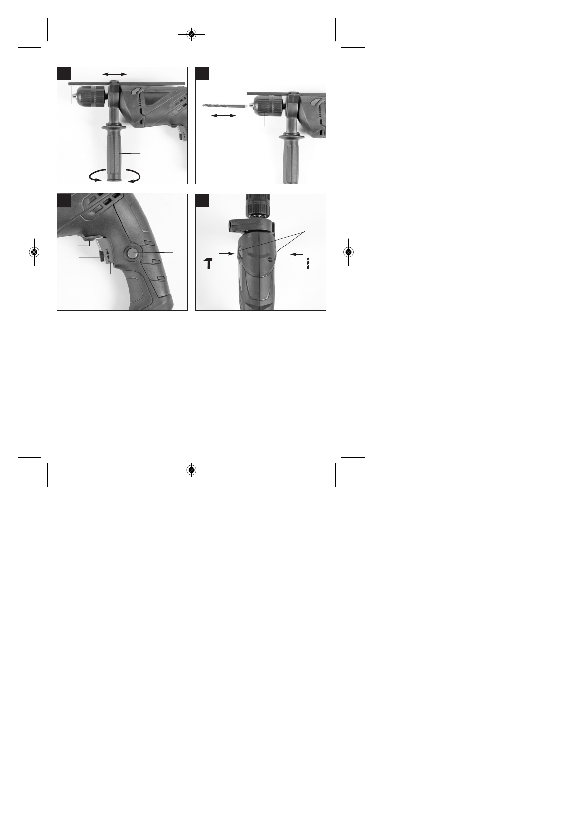
6.1. Zusatzhandgriff montieren (Bild 2-3/Pos. 8)
Der Zusatzhandgriff (8) bietet Ihnen während der Be-
nutzung der Schlagbohrmaschine zusätzlichen Halt.
Benutzen Sie das Gerät daher nicht ohne den Zu-
satzhandgriff.
Befestigt wird der Zusatzhandgriff (8) an der Schlag-
bohrmaschine durch Klemmung. Durch drehen des
Griffes im Uhrzeigersinn wird die Klemmung angezo-
gen. Drehen gegen den Uhrzeigersinn löst die
Klemmung.
Anleitung_BID_650_1_SPK1__ 03.09.13 11:19 Seite 7

nDer beiliegende Zusatzhandgriff (8) muss zu-
nächst montiert werden. Hierzu ist durch Drehen
des Griffes die Klemmung weit genug zu öffnen,
damit der Zusatzhandgriff über das Bohrfutter (1)
auf die Schlagbohrmaschine geschoben werden
kann.
nNach dem Aufschieben des Zusatzhandgriffes
(8) schwenken Sie diesen in die für Sie
angenehmste Arbeitsposition.
nJetzt den Griff in entgegengesetzter Drehrichtung
wieder zudrehen, bis der Zusatzhandgriff fest
sitzt.
nDer Zusatzhandgriff (8) ist für Rechtshänder
ebenso wie für Linkshänder geeignet.
6.2 Tiefenanschlag montieren und einstellen
(Bild 4/Pos. 2)
Der Tiefenanschlag (2) wird vom Zusatzhandgriff (8)
durch Klemmung gehalten. Die Klemmung wird
wieder durch Drehen des Griffes gelöst bzw.
festgezogen.
nLösen Sie die Klemmung und setzen Sie den
Tiefenanschlag (2) in die dafür vorgesehene
Aussparung des Zusatzhandgriffes ein.
nBringen Sie den Tiefenanschlag (2) auf gleiche
Ebene zum Bohrer.
nZiehen Sie den Tiefenanschlag um die
gewünschte Bohrtiefe zurück.
nDrehen Sie den Griff des Zusatzhandgriffes (8)
wieder zu bis dieser fest sitzt.
nBohren Sie nun das Loch, bis der Tiefenanschlag
(2) das Werkstück berührt.
6.3 Einsetzen des Bohrers (Bild 5)
nZiehen Sie immer den Netzstecker, bevor Sie
Einstellungen am Gerät vornehmen.
nTiefenanschlag (2) wie in 6.2 beschrieben lösen
und in Richtung Bohrergriff schieben. Somit hat
man freien Zugang zum Bohrfutter (1).
nDiese Schlagbohrmaschine ist mit einem
Schnellspann-Bohrfutter (1) ausgestattet.
nDrehen Sie das Bohrfutter (1) auf. Die
Bohreröffnung muss groß genug sein, um den
Bohrer aufzunehmen.
nWählen Sie einen geeigneten Bohrer aus.
Schieben Sie das Werkzeug soweit wie möglich
in die Bohrfutteröffnung hinein.
nDrehen Sie das Bohrfutter (1) zu. Prüfen Sie, ob
der Bohrer fest im Bohrfutter (1) sitzt.
nÜberprüfen Sie in regelmäßigen Abständen den
festen Sitzt des Bohrers bzw. Werkzeuges
(Netzstecker ziehen!).
7. Bedienung
7.1 Ein/Ausschalter (Bild 6/Pos. 5)
nSetzen Sie zuerst einen geeigneten Bohrer in
das Gerät ein (siehe 6.3).
nVerbinden Sie den Netzstecker mit einer
geeigneten Steckdose.
nSetzen Sie die Bohrmaschine direkt an der
Bohrstelle an.
Einschalten:
Ein-/Ausschalter (5) drücken
Dauerbetrieb:
Ein-/Ausschalter (5) mit Feststellknopf (4) sichern.
Ausschalten:
Ein-/Ausschalter (5) kurz eindrücken.
7.2 Drehzahl einstellen (Bild 6/Pos. 5)
nSie können die Drehzahl während des Betriebes
stufenlos steuern.
nDurch mehr oder wenig starkes Drücken des Ein-
/Ausschalters (5) wählen Sie die Drehzahl.
nWahl der richtigen Drehzahl: Die am besten
geeignete Drehzahl ist abhängig vom Werkstück,
von der Betriebsart und vom eingesetzten
Bohrer.
nGeringer Druck auf Ein-/Ausschalter (5):
niedrigere Drehzahl (Geeignet für: kleine
Schrauben, weiche Werkstoffe)
nGrößerer Druck auf Ein-/Ausschalter (5): höhere
Drehzahl (Geeignet für: große/lange Schrauben,
harte Werkstoffe)
Tipp: Bohren Sie Bohrlöcher mit geringer Drehzahl
an. Erhöhen Sie Die Drehzahl danach schrittweise.
Vorteile:
nDer Bohrer ist beim Anbohren leichter zu
kontrollieren und rutscht nicht ab.
nSie vermeiden zersplitterte Bohrlöcher (z.B. bei
Kacheln).
7.3 Vorwählen der Drehzahl (Bild 6/Pos. 6)
nDer Drehzahl-Einstellring (6) ermöglicht es Ihnen,
die maximale Drehzahl zu definieren. Der Ein-
/Ausschalter (5) kann nur noch bis zur
vorgegebenen Maximaldrehzahl eingedrückt
werden.
nStellen Sie die Drehzahl mit dem Einstellring (6)
im Ein-/Ausschalter (5) ein.
nNehmen Sie diese Einstellung nicht während des
Bohrens vor.
D
8
Anleitung_BID_650_1_SPK1__ 03.09.13 11:19 Seite 8

D
9
7.4 Rechts-/Linkslauf-Umschalter (Bild 6/Pos. 7)
nNur im Stillstand umschalten!
nStellen Sie mit dem Rechts-/Linkslauf-
Umschalter (7) die Laufrichtung des
Schlagbohrers ein:
Laufrichtung Schalterposition
Rechtslauf (Vorwärts und Bohren) R
Linkslauf (Rücklauf) L
7.5 Bohren/Schlagbohren-Umschalter
(Bild 7/Pos. 3)
nNur im Stillstand umschalten!
Bohren:
Bohren-/Schlagbohren-Umschalter (3) in Stellung
Bohren. (Position A)
Anwendung: Hölzer; Metalle; Kunststoffe
Schlagbohren:
Bohren-/Schlagbohren-Umschalter (3) in Stellung
Schlagbohren. (Position B)
Anwendung: Beton; Gestein; Mauerwerk
7.6 Tipps für das Arbeiten mit Ihrer
Schlagbohrmaschine
7.6.1 Bohren von Beton und Mauerwerk
nStellen Sie den Bohren/Schlagbohren
Umschalter (3) auf die Position B
(Schlagbohren).
nBenutzen Sie für das Bearbeiten von Mauerwerk
oder Beton immer Hartmetallbohrer und eine
hohe Drehzahleinstellung.
7.6.2 Bohren von Stahl
nStellen Sie den Bohren/Schlagbohren
Umschalter (3) auf die Position A (Bohren).
nBenutzen Sie für das Bearbeiten von Stahl
immer HSS-Bohrer (HSS = Hochlegierter
Schnellarbeitsstahl) und eine niedrige
Drehzahleinstellung.
nEs ist empfehlenswert die Bohrung durch ein
geeignetes Kühlmittel zu schmieren um
unnötigen Bohrerverschleiß zu vermeiden.
7.6.3 Schrauben eindrehen/lösen
nStellen Sie den Bohren/Schlagbohren
Umschalter (3) auf die Position A (Bohren).
nBenutzen Sie eine niedrige Drehzahleinstellung.
7.6.4 Löcher anbohren
Falls Sie ein tiefes Loch in ein hartes Material (wie
etwa Stahl) bohren möchten, empfehlen wir, dass
Sie das Loch mit einem kleineren Bohrer vorbohren.
7.6.5 Bohren in Fliesen und Kacheln
nStellen Sie zum Anbohren den Umschalter
Bohren/Schlagbohren (3) auf die Position A
(Bohren).
nStellen Sie den Umschalter
Bohren/Schlagbohren (3) auf die Position B
(Schlagbohren), sobald der Bohrer die
Fliese/Kachel durchschlagen hat.
8. Austausch der
Netzanschlussleitung
Wenn die Netzanschlussleitung dieses Gerätes
beschädigt wird, muss sie durch den Hersteller oder
seinen Kundendienst oder eine ähnlich qualifizierte
Person ersetzt werden, um Gefährdungen zu
vermeiden.
9. Reinigung, Wartung und
Ersatzteilbestellung
Ziehen Sie vor allen Reinigungsarbeiten den
Netzstecker.
9.1 Reinigung
nHalten Sie Schutzvorrichtungen, Luftschlitze und
Motorengehäuse so staub- und schmutzfrei wie
möglich. Reiben Sie das Gerät mit einem
sauberen Tuch ab oder blasen Sie es mit
Druckluft bei niedrigem Druck aus.
nWir empfehlen, dass Sie das Gerät direkt nach
jeder Benutzung reinigen.
nReinigen Sie das Gerät regelmäßig mit einem
feuchten Tuch und etwas Schmierseife.
Verwenden Sie keine Reinigungs- oder
Lösungsmittel; diese könnten die Kunststoffteile
des Gerätes angreifen. Achten Sie darauf, dass
kein Wasser in das Geräteinnere gelangen kann.
9.2 Kohlebürsten
Bei übermäßiger Funkenbildung lassen Sie die
Kohlebürsten durch eine Elektrofachkraft überprüfen.
Achtung! Die Kohlebürsten dürfen nur von einer
Elektrofachkraft ausgewechselt werden.
Anleitung_BID_650_1_SPK1__ 03.09.13 11:19 Seite 9

9.3 Wartung
Im Geräteinneren befinden sich keine weiteren zu
wartenden Teile.
9.4 Ersatzteilbestellung:
Bei der Ersatzteilbestellung sollten folgende
Angaben gemacht werden;
nTyp des Gerätes
nArtikelnummer des Gerätes
nIdent-Nummer des Gerätes
nErsatzteilnummer des erforderlichen Ersatzteils
Aktuelle Preise und Infos finden Sie unter
www.isc-gmbh.info
10. Lagerung
Lagern Sie das Gerät und dessen Zubehör an einem
dunklen, trockenen und frostfreiem sowie für Kinder
unzugänglichem Ort. Die optimale Lagertemperatur
liegt zwischen 5 und 30 ˚C. Bewahren Sie das
Elektrowerkzeug in der Originalverpackung auf.
11. Entsorgung und Wiederverwertung
Das Gerät befindet sich in einer Verpackung um
Transportschäden zu verhindern. Diese Verpackung
ist Rohstoff und ist somit wieder verwendbar oder
kann dem Rohstoffkreislauf zurückgeführt werden.
Das Gerät und dessen Zubehör bestehen aus ver-
schiedenen Materialien, wie z.B. Metall und Kunst-
stoffe. Führen Sie defekte Bauteile der Sondermüll-
entsorgung zu. Fragen Sie im Fachgeschäft oder in
der Gemeindeverwaltung nach!
10
D
Anleitung_BID_650_1_SPK1__ 03.09.13 11:19 Seite 10
11
GB
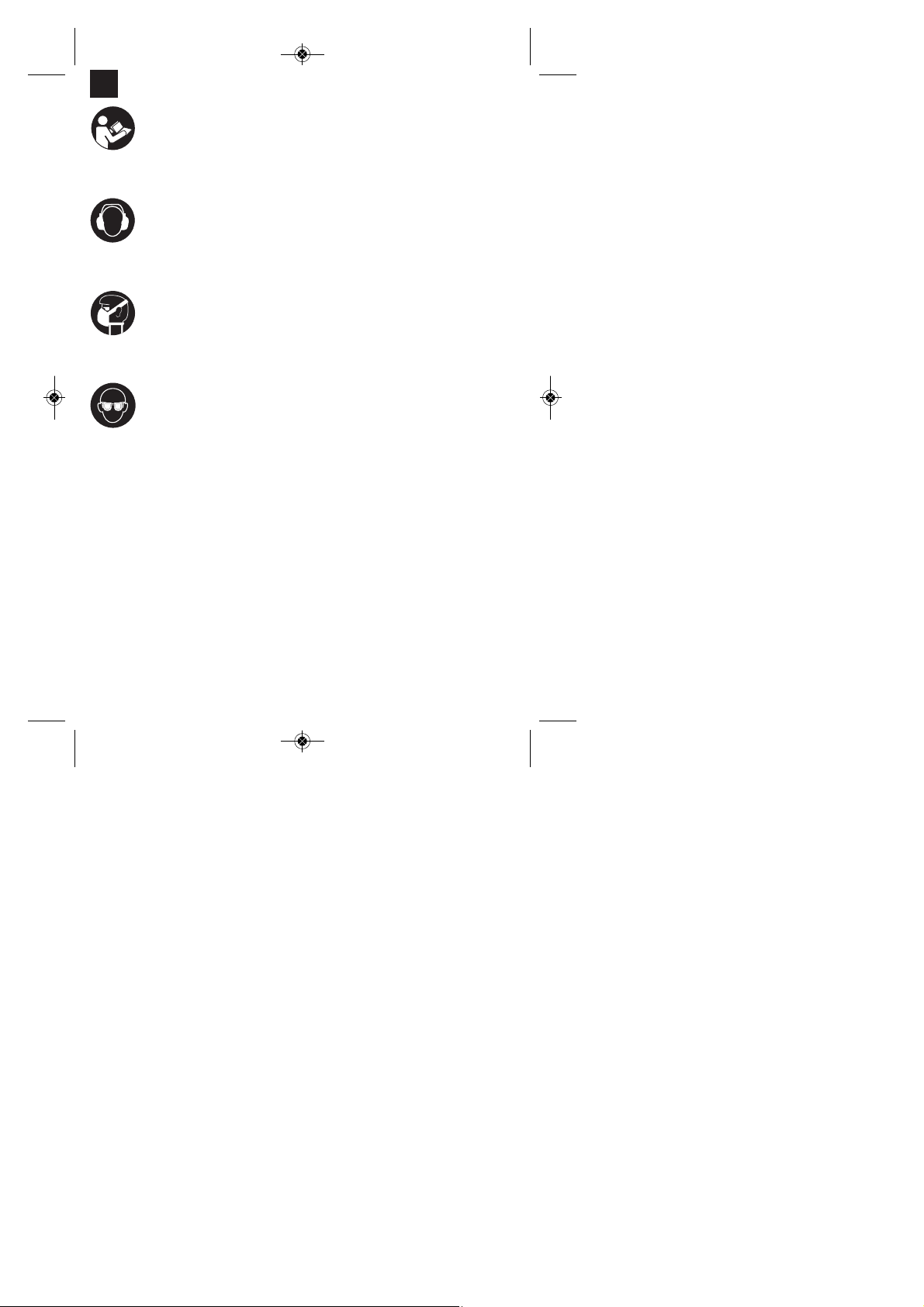
“Caution - Read the operating instructions to reduce the risk of inquiry”
Wear ear-muffs.
The impact of noise can cause damage to hearing.
Wear a breathing mask.
Dust which is injurious to health can be generated when working on wood and other materials.
Never use the device to work on any materials containing asbestos!
Wear safety goggles.
Sparks generated during working or splinters, chips and dust emitted by the device can cause
loss of sight.
Anleitung_BID_650_1_SPK1__ 03.09.13 11:19 Seite 11

12
GB
Important!
When using equipment, a few safety precautions
must be observed to avoid injuries and damage.
Please read the complete operating manual with due
care. Keep this manual in a safe place, so that the
information is available at all times. If you give the
equipment to any other person, give them these
operating instructions as well.
We accept no liability for damage or accidents which
arise due to non-observance of these instructions
and the safety information.
1. Safety regulations
The corresponding safety information can be found
in the enclosed booklet.
CAUTION!
Read all safety regulations and instructions.
Any errors made in following the safety regulations
and instructions may result in an electric shock, fire
and/or serious injury.
Keep all safety regulations and instructions in a
safe place for future use.
2. Layout (Fig. 1)
1. Drill chuck
2. Drill depth stop
3. Drill/hammer drill selector switch
4. Locking button
5. ON/OFF switch
6. Speed controller
7. Clockwise/Counter-clockwise switch
8. Additional handle
3. Items supplied
nOpen the packaging and take out the equipment
with care.
nRemove the packaging material and any
packaging and/or transportation braces (if
available).
nCheck to see if all items are supplied.
nInspect the equipment and accessories for
transport damage.
nIf possible, please keep the packaging until the
end of the guarantee period.
IMPORTANT
The equipment and packaging material are not
toys. Do not let children play with plastic bags,
foils or small parts.There is a danger of
swallowing or suffocating!
nHammer Drill
nDrill depth stop
nAdditional handle
nOriginal operating instructions
nSafety instructions
4. Proper use
The drill is designed for drilling holes into wood, iron,
non-ferrous metals and rock using the appropriate
bits.
The equipment is to be used only for its prescribed
purpose. Any other use is deemed to be a case of
misuse. The user / operator and not the
manufacturer will be liable for any damage or injuries
of any kind caused as a result of this.
Please note that our equipment has not been
designed for use in commercial, trade or industrial
applications. Our warranty will be voided if the
machine is used in commercial, trade or industrial
businesses or for equivalent purposes.
5. Technical data
Mains voltage: 230-240 V ~ 50 Hz
Power input: 600 W
Idling speed: 0-2900 min-1
Drilling capacity Concrete 13 mm
Steel 10 mm
Wood 25 mm
Protection class: II / 쓑
Weight: 1.8 kg
Anleitung_BID_650_1_SPK1__ 03.09.13 11:19 Seite 12

GB
13
Sound and vibration
Sound and vibration values were measured in
accordance with EN 60745.
LpA sound pressure level 92.9 dB(A)
KpA uncertainty 3 dB
LWA sound power level 103.9 dB(A)
KWA uncertainty 3 dB
Wear ear-muffs.
The impact of noise can cause damage to hearing.
Total vibration values (vector sum of three directions)
determined in accordance with EN 60745.
Hammer drilling in concrete
Vibration emission value ah= 8.06 m/s2
K uncertainty = 1.5 m/s2
Drilling in metal
Vibration emission value ah≤ 6.35 m/s2
K uncertainty = 1.5 m/s2
Additional information for electric power tools
Warning!
The specified vibration value was established in
accordance with a standardized testing method. It
may change according to how the electric equipment
is used and may exceed the specified value in
exceptional circumstances.
The specified vibration value can be used to compare
the equipment with other electric power tools.
The specified vibration value can be used for initial
assessment of a harmful effect.
Keep the noise emissions and vibrations to a
minimum.
nOnly use appliances which are in perfect working
order.
nService and clean the appliance regularly.
nAdapt your working style to suit the appliance.
nDo not overload the appliance.
nHave the appliance serviced whenever
necessary.
nSwitch the appliance off when it is not in use.
nWear protective gloves.
Residual risks
Even if you use this electric power tool in
accordance with instructions, certain residual
risks cannot be rules out. The following hazards
may arise in connection with the equipment’s
construction and layout:
1. Lung damage if no suitable protective dust mask
is used.
2. Damage to hearing if no suitable ear protection is
used.
3. Health damage caused by hand-arm vibrations if
the equipment is used over a prolonged period or
is not properly guided and maintained.
6. Before starting the equipment
Before you connect the equipment to the mains
supply make sure that the data on the rating plate
are identical to the mains data.
Always pull the power plug before making
adjustments to the equipment.
6.1. Fitting the additional handle (Fig. 2-3/Item 8)
The additional handle (8) enables you to achieve
better stability whilst using the hammer drill. Do not
use the tool without the additional handle.
The additional handle (8) is secured to the hammer
drill by a clamp. During the handle clockwise tightens
this clamp. Turning it anti-clockwise will release the
clamp.
nThe supplied additional handle (8) must first be
fitted. To do this, the clamp must be opened by
turning the handle until it is wide enough for the
additional handle to be slid over the chuck (1)
and on to the hammer drill.
nAfter you have positioned the additional handle
(8), turn it to the most comfortable working
position for you.
nNow turn the handle in the opposite direction
again until the additional handle is secure.
nThe additional handle (8) is suitable for both left-
handed and right-handed users.
6.2 Fitting and adjusting the depth stop
(Fig. 4/Item 2)
The depth stop (2) is held in place by the additional
handle (8) by clamping. The clamp can be released
and tightened by turning the handle.
nRelease the clamp and fit the depth stop (2) in
the recess provided for it in the additional handle.
nSet the depth stop (2) to the same level as the
drill bit.
nPull the depth stop back by the required drilling
depth.
Anleitung_BID_650_1_SPK1__ 03.09.13 11:19 Seite 13

14
GB
nTurn the handle on the additional handle (8) until
it is secure.
nNow drill the hole until the depth stop (2) touches
the workpiece.
6.3 Fitting the drill bit (Fig. 5)
nAlways pull the power plug before making
adjustments to the equipment.
nRelease the depth stop as described in 6.2 and
push it towards the additional handle. This
provides free access to the chuck (1).
nThis hammer drill is fitted with a keyless chuck
(1).
nOpen the chuck (1). The drill bit opening (1) must
be large enough to fit the drill bit into.
nSelect a suitable drill bit. Push the drill bit as far
as possible into the chuck opening.
nClose the chuck (1). Check that the drill bit is
secure in the chuck (1).
nCheck at regular intervals that the drill bit or tool
is secure (pull the mains plug).
7. Operation
7.1 ON/OFF switch (Fig. 6/Item 5)
nFirst fit a suitable drill bit into the tool (see 6.3).
nConnect the mains plug to a suitable socket.
nPosition the drill in the position you wish to drill.
To switch on:
Press the ON/OFF switch (5)
Continuous operation:
Secure the ON/OFF switch (5) with the locking
button (4).
To switch off:
Press the ON/OFF switch (5) briefly.
7.2 Adjusting the speed (Fig. 6/Item 5)
nYou can infinitely vary the speed whilst using the
tool.
nSelect the speed by applying a greater or lesser
pressure to the ON/OFF switch (5).
nSelect the correct speed: The most suitable
speed depends on the workpiece, the type of use
and the drill bit used.
nLow pressure on the ON/OFF switch (5): Lower
speed (suitable for: small screws and soft
materials)
nGreater pressure on the ON/OFF switch (5):
Higher speed (suitable for large/long screws and
hard materials)
Tip: Start drilling holes at low speed. Then increase
the speed in stages.
Benefits:
nThe drill bit is easier to control when starting the
hole and will not slide away.
nYou avoid drilling messy holes (for example in
tiles).
7.3 Preselecting the speed (Fig. 6/Item 6)
nThe speed setting ring (6) enables you to define
the maximum speed. The ON/OFF switch (5) can
only be pressed to the defined maximum speed
setting.
nSet the speed using the setting ring (6) on the
ON/OFF switch (5).
nDo not attempt to make this setting whilst the drill
is in use.
7.4 Clockwise/Counter-clockwise switch
(Fig. 6/Item 7)
nChange switch position only when the drill is
at a standstill!
nSwitch the direction of the hammer drill using the
clockwise/counter-clockwise switch (7):
Direction Switch position
Clockwise (forwards and drill) R
Counter-clockwise (reverse) L
7.5 Drill / hammer drill selector switch
(Fig. 7/Item 3)
Change switch position only when the drill is at a
standstill!
Drill
Drill / hammer drill selector switch (3) in the drill
position. (Position A)
Use for: Wood, metal, plastic
Hammer drill
Drill / hammer drill selector switch (3) in the hammer
drill position. (Position B)
Use for: Concrete, rock, masonry
7.6 Tips for working with your hammer drill
7.6.1 Drilling concrete and masonry
nSwitch the Drill/Hammer drill selector switch (3)
to position B (Hammer drill).
nAlways use carbide drill bits and a high speed
setting for drilling into masonry and concrete.
Anleitung_BID_650_1_SPK1__ 03.09.13 11:19 Seite 14

15
GB
7.6.2 Drilling steel
nSwitch the drill / hammer drill selector switch (3)
to position A (drill).
nAlways use HSS drill bits (HSS = high speed
steel) and a low speed setting for drilling steel.
nWe recommend that you lubricate the hole with a
suitable cutting fluid to prevent unnecessary drill
bit wear.
7.6.3 Inserting/Removing screws
nSwitch the Drill/Hammer drill selector switch (3)
to position A (drill).
nUse a low speed setting
7.6.4 Starting holes
If you wish to drill a deep hole in a hard material
(such as steel), we recommend that you start the
hole with a smaller drill bit.
7.6.5 Drilling tiles
nTo start the hole, switch the drill / hammer drill
selector switch (3) to position A (drill).
nSwitch the drill / hammer drill selector switch (3)
to position B (hammer drill) as soon as the drill
bit has passed through the tiles.
8. Replacing the power cable
If the power cable for this equipment is damaged, it
must be replaced by the manufacturer or its after-
sales service or similarly trained personnel to avoid
danger.
9. Cleaning, maintenance and
ordering of spare parts
Always pull out the mains power plug before starting
any cleaning work.
9.1 Cleaning
nKeep all safety devices, air vents and the motor
housing free of dirt and dust as far as possible.
Wipe the equipment with a clean cloth or blow it
with compressed air at low pressure.
nWe recommend that you clean the device
immediately each time you have finished using it.
nClean the equipment regularly with a moist cloth
and some soft soap. Do not use cleaning agents
or solvents; these could attack the plastic parts of
the equipment. Ensure that no water can seep
into the device.
9.2 Carbon brushes
In case of excessive sparking, have the carbon
brushes checked only by a qualified electrician.
Important! The carbon brushes should not be rep
laced by anyone but a qualified electrician.
9.3 Maintenance
There are no parts inside the equipment which
require additional maintenance.
9.4 Ordering replacement parts:
Please quote the following data when ordering
replacement parts:
nType of machine
nArticle number of the machine
nIdentification number of the machine
nReplacement part number of the part required
For our latest prices and information please go to
www.isc-gmbh.info
10. Storage
Store the equipment and accessories out of children’s
reach in a dark and dry place at above freezing
temperature.The ideal storage temperature is
between 5 and 30 °C.Store the electric tool in its
original packaging.
11. Disposal and recycling
The unit is supplied in packaging to prevent its being
damaged in transit. This packaging is raw material
and can therefore be reused or can be returned to
the raw material system.
The unit and its accessories are made of various
types of material, such as metal and plastic.
Defective components must be disposed of as
special waste. Ask your dealer or your local council.
Anleitung_BID_650_1_SPK1__ 03.09.13 11:19 Seite 15
16
F
«Avertissement – Lisez ce mode dʼemploi pour diminuer le risque de blessures»
Portez une protection de lʼouïe.
Lʼexposition au bruit peut entraîner une perte de lʼouïe.
Portez un masque anti-poussière.
Lors de travaux sur su bois et autres matériaux, de la poussière nuisible à la santé peut être
dégagée. Ne travaillez pas sur du matériau contenant de lʼamiante !
Portez des lunettes de protection.
Les étincelles générées pendant travail ou les éclats, copeaux et la poussière sortant de
lʼappareil peuvent entraîner une perte de la vue.
Anleitung_BID_650_1_SPK1__ 03.09.13 11:19 Seite 16

17
F
Attention !
Lors de lʼutilisation dʼappareils, il faut respecter
certaines mesures de sécurité afin dʼéviter des
blessures et dommages. Veuillez donc lire
attentivement ce mode dʼemploi. Conservez-le bien
de façon à pouvoir disposer à tout moment de ces
informations. Si lʼappareil doit être remis à dʼautres
personnes, remettez-leur aussi ce mode dʼemploi.
Nous déclinons toute responsabilité pour les
accidents et dommages dus au non-respect de ce
mode dʼemploi et des consignes de sécurité.
1. Consignes de sécurité:
Vous trouverez les consignes de sécurité
correspondantes dans le cahier en annexe.
AVERTISSEMENT !
Veuillez lire toutes les consignes de sécurité et
instructions.
Tout non-respect des consignes de sécurité et
instructions peut provoquer une décharge électrique,
un incendie et/ou des blessures graves.
Conservez toutes les consignes de sécurité et
instructions pour une consultation ultérieure.
2. Description de lʼappareil (figure 1)
1. Mandrin de perceuse
2. Butée de profondeur de perçage
3. Commutateur de perçage/perçage à percussion
4. Bouton de fixation
5. Interrupteur Marche / Arrêt
6. Régulateur de vitesse de rotation
7. Commutateur de rotation à droite / à gauche
8. Poignée supplémentaire
3. Volume de livraison
nOuvrez l’emballage et prenez l’appareil en le
sortant avec précaution de l’emballage.
nRetirez le matériel d’emballage tout comme les
sécurités d’emballage et de transport (s’il y en a).
nVérifiez si la livraison est bien complète.
nContrôlez si l’appareil et ses accessoires ne sont
pas endommagés par le transport.
nConservez l’emballage autant que possible
jusqu’à la fin de la période de garantie.
ATTENTION
L’appareil et le matériel d’emballage ne sont pas
des jouets ! Il est interdit de laisser des enfants
jouer avec des sacs et des films en plastique et
avec des pièces de petite taille. Ils risquent de
les avaler et de s’étouffer !
nPerceuse électrique à percussion
nButée de profondeur de perçage
nPoignée supplémentaire
nMode d’emploi d’origine
nConsignes de sécurité
4. Utilisation conforme à lʼaffectation
La perceuse est conçue pour le perçage de trous
dans le bois, le fer, les métaux lourds non-ferreux et
la pierre en employant l'outil de perçage
correspondant.
La machine doit exclusivement être employée
conformément à son affectation. Chaque utilisation
allant au-delà de cette affectation est considérée
comme non conforme. Pour les dommages en
résultant ou les blessures de tout genre, le
producteur décline toute responsabilité et
lʼopérateur/lʼexploitant est responsable.
Veillez au fait que nos appareils, conformément à
leur affectation, nʼont pas été construits, pour être
utilisés dans un environnement professionnel,
industriel ou artisanal. Nous déclinons toute
responsabilité si lʼappareil est utilisé
professionnellement, artisanalement ou dans des
sociétés industrielles, tout comme pour toute activité
équivalente.
5. Données techniques
Tension du réseau : 230-240 V~50 Hz
Puissance absorbée : 600 W
Vitesse de marche à vide : 0-2900 tr/min
Capacité de perçage Béton 13 mm
Acier 10 mm
Bois 25 mm
Catégorie de protection : II / 쓑
Poids: 1,8 kg
Anleitung_BID_650_1_SPK1__ 03.09.13 11:19 Seite 17

18
F
Bruit et vibration
Les valeurs de bruit et de vibration ont été
déterminées conformément à la norme EN 60745.
Niveau de pression acoustique LpA 92,5 dB(A)
Imprécision KpA 3 dB
Niveau de puissance acoustique LWA 103,5 dB(A)
Imprécision KWA 3 dB
Portez une protection acoustique.
Lʼexposition au bruit peut entraîner la perte de lʼouïe.
Les valeurs totales des vibrations (somme des
vecteurs de trois directions) ont été déterminées
conformément à EN 60745.
Perçage à percussion dans le béton
Valeur dʼémission des vibrations ah= 8,06 m/s2
Imprécision K = 1,5 m/s2
Perçage dans le métal
Valeur dʼémission des vibrations ah≤ 6,35 m/s2
Imprécision K = 1,5 m/s2
Informations supplémentaires sur les outils
électriques
Avertissement !
La valeur d’émission de vibration a été mesurée selon
une méthode d’essai normée et peut être modifiée,
en fonction du type d’emploi de l’outil électrique ; elle
peut dans certains cas exceptionnels être supérieure
à la valeur indiquée.
La valeur d’émission de vibration indiquée peut être
utilisée pour comparer un outil électrique à un autre.
La valeur d’émission de vibration indiquée peut
également être utilisée pour estimer l’altération au
début.
Limitez le niveau sonore et les vibrations à un
minimum !
nUtilisez exclusivement des appareils en excellent
état.
nEntretenez et nettoyez l’appareil régulièrement.
nAdaptez votre façon de travailler à l’appareil.
nNe surchargez pas l’appareil.
nFaites contrôler l’appareil le cas échéant.
nMettez l’appareil hors circuit lorsque vous ne
l’utilisez pas.
nPortez des gants.
Risques résiduels
Même en utilisant cet outil électrique
conformément aux prescriptions, il reste
toujours des risques résiduels. Les dangers
suivants peuvent apparaître en rapport avec la
construction et le modèle de cet outil électrique :
1. Lésions des poumons si aucun masque anti-
poussière adéquat n’est porté.
2. Déficience auditive si aucun casque anti-bruit
approprié n’est porté.
3. Atteintes à la santé issues des vibrations main-
bras, si l’appareil est utilisé pendant une longue
période ou s’il n’a pas été employé ou entretenu
dans les règles de l’art.
6. Avant la mise en service
Assurez-vous, avant de connecter la machine, que
les données se trouvant sur la plaque de
signalisation correspondent bien aux données du
réseau.
Enlevez systématiquement la fiche de contact avant
de paramétrer lʼappareil.
6.1.Monter la poignée supplémentaire
(figure 2-3/pos. 8)
La poignée supplémentaire (8) vous permet dʼavoir
un meilleur appui pendant lʼutilisation de la perceuse
électrique. Nʼutilisez donc pas lʼappareil sans sa
poignée supplémentaire.
La poignée supplémentaire (8) est fixée par serrage
à la perceuse électrique à percussion. En tournant la
poignée dans le sens des aiguilles dʼune montre, on
la serre. Dans le sens contraire de celui des aiguilles
dʼune montre, on la desserre.
nLa poignée supplémentaire jointe (8) doit tout
dʼabord être montée. Pour ce faire, tourner la
poignée pour ouvrir suffisamment le système de
serrage afin de pouvoir pousser la poignée
supplémentaire par dessus le mandrin de la
perceuse (1) sur la perceuse électrique à
percussion.
nUne fois la poignée supplémentaire (8) poussée,
pilotez-la pour la mettre dans la position de
travail la plus agréable.
nMaintenant, refermer la poignée dans le sens
contraire du sens de rotation jusquʼà ce que la
poignée supplémentaire soit bien en place.
nLa poignée supplémentaire (8) convient tout
autant aux droitiers quʼaux gauchers.
Anleitung_BID_650_1_SPK1__ 03.09.13 11:19 Seite 18

19
F
6.2 Monter la butée de profondeur et la régler
(figure 4/pos. 2)
La butée de profondeur (2) est maintenue avec la
poignée supplémentaire (8) par serrage. Pour serrer
ou desserrer, tournez la poignée.
nDesserrez la poignée et introduisez la butée de
profondeur (2) dans lʼencoche prévue à cet effet
de la poignée supplémentaire.
nRéglez la butée de profondeur (2) au même
niveau que le foret.
nFaites reculer la butée de profondeur de la
profondeur de perçage désirée.
nRefermez la poignée supplémentaire (8) jusquʼà
ce quʼelle tienne correctement.
nPercez à présent le trou jusquʼà ce que la butée
de profondeur (2) touche la pièce à usiner.
6.3 Mise en place du foret (figure 5)
nEnlevez systématiquement la fiche de contact
avant de paramétrer lʼappareil.
nDesserrez la butée de profondeur comme décrit
au point 6.2 et poussez-la en direction de la
poignée supplémentaire. On a ainsi accès libre
au mandrin de perceuse (1).
nCette perceuse électrique à percussion est dotée
dʼun mandrin à serrage rapide (1).
nDévissez le mandrin (1). Lʼouverture de la
perceuse doit être assez grande pour pouvoir
engager le foret.
nSélectionnez le bon foret. Poussez le foret le
plus loin possible dans lʼouverture du mandrin.
nFermez le mandrin de perceuse (1). Contrôlez si
le foret tient bien dans le mandrin de perceuse
(1).
nContrôlez à intervalles réguliers si le foret ou
lʼoutil sont bien correctement introduits
(débranchez la prise secteur !).
7. Commande
7.1 Interrupteur Marche / Arrêt (figure 6/pos. 5)
nIntroduisez tout dʼabord un foret adéquat dans
lʼappareil (voir 6.3).
nConnectez la fiche de contact à une prise
appropriée.
nPlacer la perceuse directement sur lʼendroit à
percer.
Mise en circuit :
appuyer sur lʼinterrupteur Marche / Arrêt (5)
Fonctionnement continu :
Bloquer lʼinterrupteur Marche / Arrêt (5) avec le
bouton de fixation (4).
Mise hors circuit :
appuyez brièvement sur lʼinterrupteur Marche / Arrêt
(5).
7.2 Régler la vitesse (fig. 6/pos. 5)
nVous pouvez commander la vitesse en continu
pendant le fonctionnement.
nVous sélectionnez la vitesse en appuyant plus
ou moins fortement sur lʼinterrupteur Marche /
Arrêt (5).
nSélection de la vitesse de rotation correcte : la
vitesse la plus appropriée dépend de la pièce à
usiner, du mode de fonctionnement et du foret
employé.
nUne faible pression sur lʼinterrupteur Marche /
Arrêt (5) : vitesse extrêmement basse (convient
aux : petites vis, matériaux souples)
nUne pression plus importante sur lʼinterrupteur
Marche / Arrêt (5) : vitesse plus élevée (convient
aux : grandes/longues vis, matériaux durs)
Astuce : Percez les trous à une vitesse moins
élevée. Augmentez ensuite la vitesse petit à petit.
Avantages :
nLe foret est plus facile à contrôler pendant le
perçage et il ne glisse pas.
nVous évitez dʼobtenir des trous éclatés (par
exemple pour les carreaux)
7.3 Présélectionner la vitesse de rotation
(figure 6/pos. 6)
nLa bague de réglage de la vitesse de rotation (6)
vous permet de définir la vitesse de rotation
maximale. Lʼinterrupteur Marche / Arrêt (5) peut
uniquement être enfoncé jusquʼà la vitesse de
rotation maximale prescrite.
nRéglez la vitesse de rotation avec la bague de
réglage (6) dans lʼinterrupteur Marche / Arrêt (5).
nNʼeffectuez pas ce réglage pendant que vous
percez.
Anleitung_BID_650_1_SPK1__ 03.09.13 11:19 Seite 19

F
20
7.4 Commutateur de rotation à droite / à gauche
(figure 6/pos. 7)
nCommuter uniquement à lʼarrêt !
nRéglez le sens de rotation de la perceuse à
percussion avec le commutateur de rotation à
droite / à gauche (7) :
Sens de rotation Position du commutateur
Marche à droite (avant et perçage) R
Marche à gauche (retour) L
7.5 Commutateur de perçage / perçage à
percussion (figure 7/pos. 3)
nCommuter uniquement à lʼarrêt !
Perçage :
Commutateur de perçage/perçage à percussion (3)
en position perçage. (Position A)
Application : bois ; métaux ; matières plastiques
Perçage à percussion :
Commutateur de perçage/perçage à percussion (3)
en position perçage à percussion. (Position B)
Application : Béton ; pierre ; maçonnerie
7.6 Astuces pour le travail avec votre perceuse
électrique à percussion
7.6.1 Perçage de béton et de maçonnerie
nMettez le commutateur de perçage / perçage à
percussion (3) en position B (perçage à
percussion).
nUtilisez pour travailler de la maçonnerie ou du
béton toujours le foret pour métal dur et avec un
réglage élevé de la vitesse de rotation.
7.6.2 Perçage de lʼacier
nMettez le commutateur de perçage / perçage à
percussion (3) en position A (perçage).
nUtilisez pour le traitement de lʼacier toujours le
foret pour acier à coupe très rapide (acier à
coupe très rapide = acier fortement allié) et un
réglage de la vitesse de rotation peu élevé.
nIl est recommandé de lubrifier le perçage à lʼaide
dʼun réfrigérant approprié afin dʼéviter que le
foret ne sʼuse inutilement.
7.6.3 Serrer/desserrer les vis
nMettez le commutateur de perçage / perçage à
percussion (3) en position A (perçage).
nUtilisez un réglage de la vitesse de rotation peu
élevé.
7.6.4 Percer des trous
Si vous voulez percer un trou dans un matériau dur
(comme de lʼacier), nous vous recommandons de
percer dʼabord le trou avec un foret plus petit.
7.6.5 Perçage dans des carreaux et dalles
nPour faire le premier perçage, mettez le
commutateur perçage / perçage à percussion (3)
sur la position A (perçage).
nMettez le commutateur
perçage / perçage à percussion (3) sur la
position B (perçage à percussion), dès que le
foret a percé le carreau /la dalle.
8. Remplacement de la ligne de
raccordement réseau
Si la ligne de raccordement réseau de cet appareil
est endommagée, il faut la faire remplacer par le
producteur ou son service après-vente ou par une
personne de qualification semblable afin dʼéviter tout
risque.
9. Nettoyage, maintenance et
commande de pièces de rechange
Retirez la fiche de contact avant tous travaux de
nettoyage.
9.1 Nettoyage
nMaintenez les dispositifs de protection, les fentes
à air et le carter de moteur aussi propres (sans
poussière) que possible. Frottez lʼappareil avec
un chiffon propre ou soufflez dessus avec de lʼair
comprimé à basse pression.
nNous recommandons de nettoyer lʼappareil
directement après chaque utilisation.
nNettoyez lʼappareil régulièrement à lʼaide dʼun
chiffon humide et un peu de savon. Nʼutilisez
aucun produit de nettoyage ni détergeant ; ils
pourraient endommager les pièces en matières
plastiques de lʼappareil. Veillez à ce quʼaucune
eau nʼentre à lʼintérieur de lʼappareil.
9.2 Brosses à charbon
Si les brosses à charbon font trop dʼétincelles,
faites-les contrôler par des spécialistes en
électricité.
Attention ! Seul un(e) spécialiste électricien(ne) est
autorisé à remplacer les brosses à charbon.
Anleitung_BID_650_1_SPK1__ 03.09.13 11:19 Seite 20
This manual suits for next models
1
Table of contents
Languages:
Other Bavaria Drill manuals


