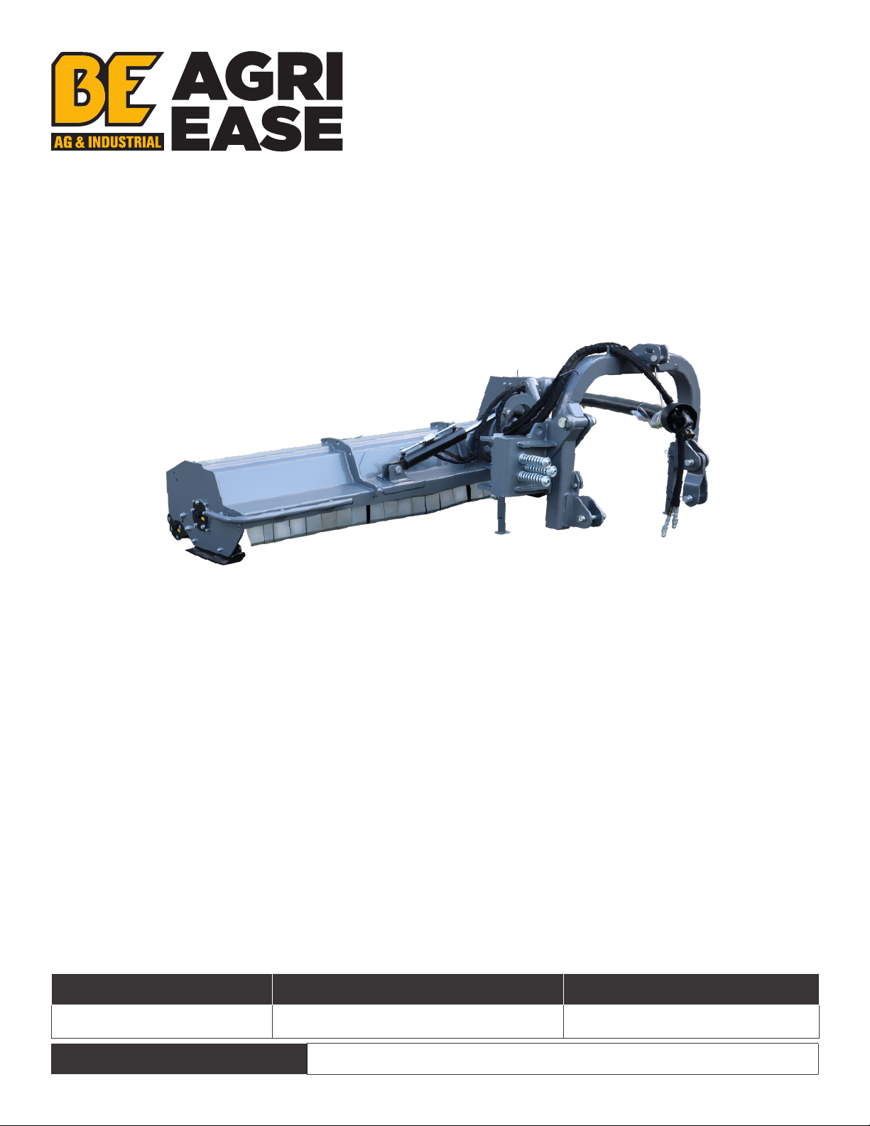
BE Ag & Industrial AGRI EASE BE-VBM220 Application guide

PURCHASE DATE MODEL NO. SERIAL NUMBER
DEALER
VERGE FLAIL
MOWER
BE-VBM220
OPERATIONS & PARTS MANUAL
FOR MODELS:
• BE-VBM220

TABLE OF CONTENTS
3SAFETY
7INTRODUCTION
8ASSEMBLY, SET-UP & OPERATING INSTRUCTIONS
9ADJUSTMENTS
10 MAINTENANCE AND LUBRICATION
11 SPECIFICATIONS & CAPACITIES
12 TROUBLESHOOTING & APPENDIX
14 EXPLODED VIEW & PARTS LIST

BE-VBM220 USER MANUAL 3
IMPORTANT SAFETY INFORMATION
Safety At All Times
Thoroughly read and understand the instructions given in this manual before operation. Refer to the “Safety
Decal” and read all instructions noted.
Do not allow anyone to operate this equipment who has not fully read and comprehended this manual and
who has not been properly trained in the safe operation of the equipment.
• Operator should be familiar with all functions of the unit.
• Operate implement from the driver’s seat only.
• Make sure all guards and shields are in place and secured before operating the implement.
• Do not leave tractor or implement unattended with engine running.
• Dismounting from a moving tractor could cause serious injury or death.
• Do not stand between tractor and implement during hitching.
• Keep hands, feet, and clothing away from power-driven parts.
• Wear snug fitting clothing to avoid entanglement with moving parts.
• Watch out for wires, trees, etc., when raising implement. Make sure all persons are clear of working area.
• Turning tractor too tight may cause implement to ride up on wheels. This could result in injury or
equipment damage.
Look For the Safety Alert Symbol
The SAFETY ALERT SYMBOL indicates there is a potential hazard to personal safety involved and extra
safety precaution must be taken. When you see this symbol, be alert and carefully read the message that
follows it. In addition to design and configuration of equipment, hazard control and accident prevention
are dependent upon the awareness, concern, prudence and proper training of personnel involved in the
operation, transport, maintenance and storage of equipment.
Be Aware Of Signal Words
A signal word designates a degree or level of hazard seriousness. The signal words are:
DANGER
Indicates an imminently hazardous situation which, if not avoided, will result in death or serious injury. This
signal word is limited to the most extreme situations, typically for machine components that, for functional
purpose, cannot be guarded.
WARNING
Indicates a potentially hazardous situation which, if not avoided, could result in death or serious injury, and
includes hazards that are exposed when guards are removed. It may also be used to alert against unsafe
practices.
CAUTION
Indicates a potentially hazardous situation which, if not avoided, may result in minor or moderate injury. It
may also be used to alert against unsafe practices.
For Your Protection
• Thoroughly read and understand the “safety label” section, read all instructions noted.
Shutdown And Storage
• Lower machine to ground, put tractor in park, turn o engine, and remove ignition key.
• Detach and store implements in an area where children normally do not play. Secure implement by using
blocks and supports.
Use Safety Lights And Devices
• Slow moving tractors, self-propelled equipment, and towed implements can create a hazard when driven
on public roads. They are dicult to see, especially at night.
• Flashing warning lights and turn signals are recommended whenever driving on public roads. Use lights
and devices provided with implement.

4 BE-VBM220 USER MANUAL
Transport Machinery Safely
• Comply with state and local laws.
• Maximum transport speed for implement is 20 mph. Do not exceed. Never travel at a speed which does not
allow adequate control of steering and stopping. Rough terrain requires a slower speed.
• Sudden braking can cause a towed load to swerve and upset. Reduce speed if towed load is not equipped
with brakes.
• Use the following maximum speed - tow load weight ratios as a guideline: 20 mph when weight is less than
or equal to the weight of tractor. 10 mph when weight is double the weight of tractor.
• IMPORTANT: Do not tow a load that is more than double the weight of tractor.
Keep Riders O Machinery
• Riders obstruct the operator’s view. They can be struck by foreign objects or thrown from the machine.
• Never allow children to operate equipment.
Practice Safe Maintenance
• Understand all procedures before doing work. Use proper tools and equipment. Refer to Operator’s Manual
for additional information.
• Work in a clean dry area.
• Lower implement to the ground, put tractor in park, turn o engine, and remove key before performing
maintenance.
• Allow implement to cool completely.
• Do not grease or oil implement while it is in operation.
• Inspect all parts. Make sure parts are in good condition and installed properly.
• Remove buildup of grease, oil and debris.
• Remove all tools and unused parts from implement before operation.
Prepare For Emergencies
• Be prepared if a fire starts.
• Keep a first aid kit and fire extinguisher handy.
• Keep emergency numbers for doctor, ambulance, hospital and fire department near phone.
Wear Protective Equipment
• Protective clothing and equipment should be worn.
• Wear clothing and equipment appropriate for the job. Avoid loose fitting clothing.
• Prolonged exposure to loud noise can cause hearing impairment or hearing loss.
Wear suitable hearing protection such as earmus or earplugs.
• Operating equipment safely requires the full attention of the operator. Avoid wearing headphones while
operating machinery.
Avoid High Pressure Fluids Hazard
• Escaping fluid under pressure can penetrate the skin causing serious injury.
• Avoid the hazard by relieving pressure before disconnecting hydraulic lines.
• Use a piece of paper or cardboard, not body parts, to check for suspected leaks.
Wear protective gloves and safety glasses or goggles when working with hydraulic systems.
• If an accident occurs, see a doctor immediately. Any fluid injected into the skin must be treated within a
few hours or gangrene may result.

BE-VBM220 USER MANUAL 5
Safety Labels
Your Flail Mower comes equipped with all safety labels in place. They were designed to help you safely
operate your mower. Read and follow their directions.
1. Keep all safety labels clean and legible.
2. Replace all damaged or missing labels. To order new labels contact Braber Equipment at 1-877-588-3311.
3. Some new equipment installed during repair requires safety labels to be axed to the replaced
component as specified by Braber Equipment. When ordering new components make sure the correct
safety labels are included in the request.
4. Refer to this section for proper label placement. To install new labels:
• Clean the area where the label is to be placed.
• Spray soapy water on the surface where the label is to be placed.
• Peel backing from label. Press firmly onto surface.
• Squeeze out air bubbles with the edge of a credit card.

6 BE-VBM220 USER MANUAL
7
A
B
8
C
D
E
Introduction
Braber Equipment welcomes you to the growing family of new product owners. This
implement has been designed with care and was built by skilled workers using quality
materials. Proper assembly, maintenance, and safe operating practices will help you get
years of satisfactory use from the machine.
Application
The Flail Mowers are designed for Category 1 - three point hitch or Quick-Hitch System
mounting. These Fixed Bar Flail Mowers are ideal for ripping, leveling, finish grading, and
backfilling applications at feedlots, outdoor arenas, building sites, and maintenance
operations on farm and ranch lanes or roadways.
9

BE-VBM220 USER MANUAL 7
Introduction
Braber Equipment welcomes you to the growing family of new product owners. This implement has been
designed with care and was built by skilled workers using quality materials. Proper assembly, maintenance,
and safe operating practices will help you get years of satisfactory use from the machine.
Application
The Flail Mowers are designed for Category 1 - Three point hitch or Quick-Hitch System mounting. These
Fixed Bar Flail Mowers are ideal for ripping, leveling, finish grading, and backfilling applications at feedlots,
outdoor arenas, building sites, and maintenance operations on farm and ranch lanes or roadways.
Using This Manual
• This Operator’s Manual is designed to help familiarize you with safety, assembly, operation, adjustments,
troubleshooting, and maintenance. Read this manual and follow the recommendations to help ensure safe
and ecient operation.
• The information contained within this manual was current at the time of printing. Some parts may change
slightly to ensure continued high-quality performance.
• To order a new Operator’s or Parts Manual contact Braber Equipment at 1-877-588-3311.
Terminology
“Right” or “Left” as used in this manual is determined by facing the direction the machine
will operate while in use unless otherwise stated.
Definitions
Note: A special point of information that the operator must be aware of before continuing.
IMPORTANT:
A special point of information related to its preceding topic. The intention is that this information should be
read and noted before continuing.
Owner Assistance
The Warranty Registration card should be filled out by the dealer at the time of purchase. This information
is necessary to provide you with quality customer service. If customer service or repair parts are required
contact a dealer. A dealer has trained personnel, repair parts and equipment needed to service the machine.
The parts on your machine have been specially designed and should only be replaced with genuine parts.
Serial Number Plate
For prompt service always use the serial number and model number when ordering parts from your dealer.
Be sure to include your serial and model numbers in correspondence also.

8 BE-VBM220 USER MANUAL
ASSEMBLY AND SET-UP
Tractor Requirements
This mower is designed with a 3-Point category one hitch. Tractor horse power rating should not exceed 80
PTO horse power.
Assembly
Refer to the parts illustration.
Tractor Hook-Up
1. Be certain that the tractor draw bar will not interfere. Move the draw bar ahead or remove if required. The
draw bar should also be checked for clearance when unit is being raised for the first time.
2. Align lower link arms of tractor to hitch clevises on mower. Insert lower hitch pins into lower ball swivels
and attach lynch pins.
3. Attach tractor top link to upper floating hitch on mower with pin supplied. Secure with lock pin.
4. Adjust tractor top link in or out to place upper hitch pin vertically above or slightly behind lower hitch
pins to allow mower flotation. The mower should be run with the back 15 degrees lower than the front.
Driveline Installation
1. Slide driveline end with extended safety cone over splined shaft of gearbox and secure with attaching
device.
2. Slide driveline over tractor’s splined PTO shaft and secure with locking device of driveline.
3. Driveline should now be moved back and forth to ensure that it is secure on the PTO shaft of the tractor
and mower gearbox.
4. Attach chain from the driveline shield to one of the upper hitch braces to ensure that the shield does not
rotate.
5. Should driveline require shortening:
• Hold the half-shafts next to each other in the shortest working position and mark them.
• Shorten inner and outer guard tubes equally.
• Shorten inner and outer sliding profiles by the same length as the guard tubes.
• Proper overlap is a minimum of one-half the length of each tube, with both tubes being of equal length.
• Round o all sharp edges and remove burrs. Grease sliding profiles.
CAUTION
Tractor PTO shield and all mower guards must be in place at all times during operation!
OPERATING INSTRUCTIONS
Transporting
NOTE: Always disengage PTO before raising mower to transport position.
1. When raising the mower to transport position, be sure that driveline does not contact tractor or mower.
Adjust and set the tractor’s 3-point hitch lift height so that the driveline does not contact mower deck in
the fully raised position.
2. Be sure to reduce tractor ground speed when turning, leaving enough clearance so that the mower does
not contact obstacles such as buildings, trees or fences.
3. Select a safe ground travel speed when transporting from one area to another. When traveling on
roadways, transport in such a way that faster moving vehicles may pass safely.
4. When traveling over rough or hilly terrain, shift tractor to a lower gear.
CAUTION
When traveling on public roads, whether at night or during the day, use accessory lights and devices for
adequate warning to operators of other vehicles. Comply with all federal, state, and local laws.

BE-VBM220 USER MANUAL 9
Mowing Instructions
1. Clear area to be mowed of objects and debris that might be picked up and thrown by the mower blades.
2. Grass is best cut when it is dry. Mowing wet grass can cause clogging resulting in grass clumps behind the
mower.
3. Grass should be mowed frequently as shorter clippings deteriorate faster.
4. If mowing extremely tall grass, it is best to raise cutting height and mow the area, then lower cutting
height and mow a second time at the desired height.
Operating Instructions
Proper servicing and adjustments are the key to the long life of any machine. With careful and systematic
inspection of the mower, costly maintenance, time, and repair can be avoided.
Before beginning to mow, the following inspection should be performed:
1. Check oil level in gearbox.
2. Check that all plugs in gearbox have been replaced and tightened properly.
3. Be sure all mower knives, bolts and nuts are tight.
4. Be certain all guards and shields are in place and secure.
5. Grease driveline shaft and all other grease fittings.
6. Clear area to be mowed of rocks, branches and other foreign objects.
7. Lower mower to ground. Set tractor throttle at approximately 1/4 open. Engage PTO to start blades
rotating.
8. Operate with 540 rpm PTO tractor.
9. At first begin mowing at a slow forward speed and shift up until the desired speed is achieved,
maintaining 540 PTO rpm.
10.Mower knives will cut better at a faster blade speed than at reduced throttle.
11. After mowing the first 50 feet, stop and check to see that the mower is adjusted properly.
12. Do not make sharp turns or attempt to back up while mower is on the ground.
13. Do not engage PTO with mower in the fully raised position. Do not engage PTO at full throttle.
ADJUSTMENTS
Leveling The Mower
NOTE: Tractor and mower should be on level ground.
Leveling can be adjusted at the tractor’s 3-point arms and center link.
Cutting Height Adjustment
The machines cutting height depends on the position of the rear roller.
1. Remove the bolts that fix the roller on both sides.
2. Lift or lower both sides of roller in equal measurements.
3. Replace bolts and re-tighten.
3-Point Hitch Adjustments
The 3-point hitch system on this mower has been designed for front to back flotation when mowing on
uneven terrain. Adjust tractor’s top center link to place the upper hitch pin vertically above or slightly behind
the lower hitch pins. The mower should be run with the back 15 degrees lower than the front.
The hitch can also be adjusted from side to side by turning the adjustment handle. Turn handle until you
have achieved your desired location.
CAUTION
Engage parking brake, shut o tractor, remove key and disengage PTO before making any height
adjustments!

10 BE-VBM220 USER MANUAL
Belt Tension
CAUTION
Belt drive system under spring tension; use care to avoid bodily harm!
The belt tension should be checked after the first 20 hours of use, and then every 40 hours of use.
1. Tension on the belt can be adjusted with the belt tension bolt. Turn the bolt until desired tension is
achieved. When the belt has the correct tension the gearbox should be adjusted so that the gearbox
extension is running straight (parallel) with the flail mower. Loosen bolts at the bottom of the gearbox
and move gearbox until gearbox extension is running straight.
2. Excessive tension on the belt may lead to premature failure of belt and drive components.
CAUTION
Excessive tension on the belt may lead to premature failure of belt and drive components. Excessive tension
on the belt may also lead to a safety hazard to the operator or bystanders.
MAINTENANCE AND LUBRICATION
Maintenance
Proper servicing and adjustment is the key to the long life of any farm implement. With careful and
systematic inspection, you can avoid costly maintenance, time, and repair.
CAUTION
For safety reasons, each maintenance operation must be performed with tractor PTO disengaged, mower
lowered completely to the ground, and tractor engine shut o with ignition key removed.
• After using the mower for several hours, check all bolts to be sure they are tight and check drive belt
tension.
• Replace any worn, damaged or illegible safety decals by obtaining new decals from dealer.
Knife Replacement
IMPORTANT: Make sure that each knife is the same length as the others on the mower. This will keep the
rotor rotation balanced.
1. Remove bolt and nut.
2. Remove old knife.
3. Install new knife and existing bolt.
4. Secure with nut.
V-Belt Installation
CAUTION
Belt drive system under spring tension; use care to avoid bodily harm!
1. Remove belt guard fender and belt cover.
2. Disengage belt tension by loosening belt tension bolt until belt can be removed.
3. With tension relieved from belt remove old belt from pulleys.
4. Tighten belt tension bolt.
5. Reinstall belt guard and belt guard fender.

BE-VBM220 USER MANUAL 11
Storage
At the end of the working season or when the mower will not be used for a long period, it is good practice
to clean o any dirt or grease that may have accumulated on the mower and any of moving parts.
1. Clean as necessary.
2. Check knives for wear and replace if necessary.
3. Inspect mower for loose, damaged or worn parts and adjust or replace as needed.
4. Store unit inside if possible for longer life.
5. Repaint parts where paint is worn or scratched to prevent rust.
6. Replace all damaged or missing decals.
Lubrication
• Driveline Shaft U-Joints
Type of Lubrication: Multi-Purpose Grease
• Roller Bearing (Both Ends)
Type of Lubrication: Multi-Purpose Grease
• Cutter Rotor Bearing (Both Ends)
Type of Lubrication: Multi-Purpose Grease
• Driveline Profiles
Type of Lubrication: Multi-Purpose Grease
• Gearbox
Type of Lubrication: SAE 90W Gear Lube
Check oil level in gearbox by removing the plug located on the
right hand side. Oil should be level with bottom of plug hole. Add
oil if necessary by removing top fill plug and side plug. Add oil until
it flows from side plug hole.
Do not overfill!
IMPORTANT: Mower should be level when checking oil in gearbox!
SPECIFICATIONS & CAPACITIES
Uses:
The Verge Flail Mower is a flail mower with a hydraulic arm for clearing larger, wider areas, roadside verge,
orchards and various inclining and declining land surfaces. Specifically designed for universal use, the head
of the mower can be operated in line with the tractor or oset for verge maintenance and field boundaries.
MODEL VBM-140D VBM-160D VBM-180D VBM-200D VBM-220D
Structure Weight 644kg 672KG 705kg 705kg 804kg
Tilt-Up 90°
Tilt-Down Angle 53°
Cutting Width 1400mm 1600mm 1800cm 2000cm 2200cm
Final Type Hammer
Number of Flails 12 14 16 18 20
Vertical Extending
Distance 1780mm 1980mm 2180mm 2380mm 2880mm
Horizontal Extending
Distance 2345mm
PTO Speed 540r/min
Trator HP 50-85hp 70-110hp 80-110hp 90-120hp

12 BE-VBM220 USER MANUAL
TROUBLESHOOTING
CAUTION
Do not try to clean rear discharge area when mower is running. Bodily harm may occur!
PROBLEM SOLUTION
Belt slipping
Unplug and clean mower deck.
Remove belt guard shields and clean sheaves.
Replace belt.
Patches of uncut grass
Mow at full throttle (540 PTO rpm), check PTO speed and tractor engine.
Shift transmission to a lower gear.
Tighten belts.
Replace missing knives.
Excessive vibration
Replace knives.
Replace drive belt.
Replace pulleys or align.
Remove belt guard shields & clean debris from belt area & sheaves.
Gearbox noisy Check lubricant level.
Knives scalping grass
Raise cutting height by adjusting roller.
Change mowing pattern.
Reduce speed turns.
Uneven cut
Shift to a lower gear.
Level mower.
Replace missing knives.
Tractor loaded down by
mower
Mow at full throttle (540 PTO rpm).
Shift to a lower gear.
Clean mower.
BOLT DIAMETER
BOLT TORQUE
SAE 2 SAE 5 SAE 8
N.M. LB-FT N.M. LB-FT N.M. LB-FT
1/4” 8 6 12 9 17 12
5/16” 13 10 25 19 36 27
3/8” 27 20 45 33 63 45
7/16” 41 30 72 53 100 75
1/2” 61 45 110 80 155 115
9/16” 95 60 155 115 200 165
5/8” 128 95 215 160 305 220
3/4” 225 165 390 290 540 400
7/ 8 ” 230 170 570 420 880 650
APPENDIX
Bolt Torque
The tables shown below give correct torque values for various bolts and cap screws. Tighten all bolts to the
torques specified unless otherwise noted. Check tightness of bolts periodically, using bolt torque chart as a
guide. Replace hardware with the same strength bolt.
ENGLISH TORQUE SPECIFICATIONS

BE-VBM220 USER MANUAL 13
BOLT DIAMETER
BOLT TORQUE
8.8 10.9
N.M. LB-FT N.M. LB-FT
M3 0.5 0.4 1.8 1.3
M4 3 2.2 4.5 3.3
M5 6 4 9 7
M6 10 7 15 11
M8 25 18 35 26
M10 50 37 70 52
M12 90 66 125 92
M14 140 103 200 148
M16 225 166 310 229
M20 435 321 610 450
M24 750 553 1050 744
M30 1495 1103 2100 1550
M36 2600 1917 3675 2710
METRIC TORQUE SPECIFICATIONS
Torque figures indicated above are valid for non-greased or non-oiled threads and heads unless otherwise
specified. Therefore, do not grease or oil bolts or cap screws unless otherwise specified in this manual. When
using locking elements, increase torque values by 5%.

14 BE-VBM220 USER MANUAL
EXPLODED VIEW & PARTS LIST
Flail Mower Assembly
19
Section 8: Parts Illustration
VBM-D Flail Mower Assembly
7
3
89
10
11
12
15
16
17
22
20
8
23
24
25
26
27
28
29
30
31
12
32
33
34
36
35
13
37
38
39
4
40
18
22
41
13
42
44
45
46 13
47
48
49
50
51
18
33
52 13
14
53
34
35
13
36 54
29
30
28
27
26
55
56 57
58
59
61
22
33
18
62
63
64
4
18
65
22
66
67
68
69
70
71
66
72
73
7456
75
75
76
77
78
79
70
69
68
80 69 81
82
83 84
85 86 77
76
87
76
77
88
12
19
18
4
19
20
4
18 19
4
13
14
43
12
89
6
20
6
4
60
122
123
121
2
1
17
5
18

BE-VBM220 USER MANUAL 15
20
90
91
92
93
94
95
96
97
93
93
98
68
69
56
99
100
101
102 69
68
103
62 56
104
2
105
106
105
107
96 108
92
94
95
109
107
12
110
107
107
111
112
113
81
82
113
114
107
12
107
115
100
70
70
5
82
5
82
5
116 116
116
119
117
118
119
120

16 BE-VBM220 USER MANUAL
REF PART NUM DESCRIPTION QTY
1 GB/T 70.3 Bolt M12*35 10
2 GB/T 5782 Nut M16 7
3 VBMD220.48 Connection plate for rear 1 roller R 1
4 GB/T 5782 Locknut 10
5 GB/T 97.1 Plain washer 16 10
6 EFGC125.115A Bearing seat of rear roller 2
7 GB/T 5783 Bolt M16*45 4
8 UC207-Z Bearing UC207-Z 2
9 VBMD220.43 Scraper weldment 1
10 VBMD220.44 Roller weldment 1
11 VBMD220.42 Connection plate for rear roller L 1
12 JB/T 7940.1 Grease nipple M10*1 10
13 GB/T 97.1 Plain washer 10 39
14 GB/T 5783 Bolt M10*25 4
15 VBMD220.39 Belt cover weldment 1
16 VBMD220.29 Rear open bonnet 1
17 GB/T 5783 Bolt M12*35 2
18 GB/T 97.1 Plain washer 12 20
19 GB/T 6170 Nut M12 3
20 GB/T 5783 Bolt M12*60 4
20 VBMD220.28 Rear open bonnet 1
22 GB/T 5783 Bolt M14*40 10
23 GB/T 5783 Bolt M8*16 4
24 VBMD220.38 Plate 01 1
25 VBMD220.26 Mower deck weldment 1
26 GB 13871-94 Oil seal 55*80*8 2
27 GB/T 893.1 Circlip 80 2
28 VBMD220.34 Outside bearing seat 2
29 GB/T 893.1 Circlip 88 2
30 GB/T 281 Bearing 88 2
31 VBMD220.33 Cover weldment 1
32 GB/T 5783 Bolt M12*45 5
33 GB/T 93 Spring washer 12 15
34 GB/T 3541 Bolt M23*55 8
35 GB/T 93 Circlip 10 8
36 VBMD220.35 Cover weldment for rotor 2
37 VBMD220.27 Anti-shock weldment 1
38 GB/T 5783 Bolt M10*30 3
39 GB/T 5782 Nut M10 3
40 VBMD220.31 Skid 01 1
41 EFGC175.24C Wide fender 95 1
42 GB/T 91 Cotter 3.2*40 2
43 VBMD220.30 Bar for fender 1
44 EFGC175.24B Wide fender 55 1
45 EFGC175.24A Wide fender 95 19
46 EFGC175.24D Wide fender 95 1
47 GB/T 11544-97 V-belt 4
48 EFGC175.31 Big pulley 1
49 JBT7934 Z3 Power lock 33*80 1
REF PART NUM DESCRIPTION QTY
50 Gearbox 1
51 VBMD220.40 Gearbox mounting plate 1
52 GB/T 5783 Bolt M12*30 4
53 AGF220.41 Bottom belt cover 1
54 GB13871-94 Oil seal 55*90*8 1
55 GB/T 5782 Lock nut M14 4
56 GB/T 97.1 Plain washer 14 10
57 GB/T 5783 Bolt M14*45 4
58 GB/T 96.1 Big washer 14 4
59 EFGC175.27 Small belt pulley 1
60 JB/T7934 Z3 Power lock 40*80 1
61 VBMD220.37 Bushing 1
62 GB/T 6170 Nut M14 3
63 GB/T 5783 Bolt M14*90 2
64 VBMD220.36 Cover 02 1
65 VBMD220.32 Skid 02 1
66 200.56.011 Pin weldment 2
67 VBMD220.16 Lock pin 02 1
68 GB/T 5782 Lock nut M30 4
69 GB/T 97.1 Plain washer 30 5
70 AGF140.101 Long pin 2
71 AGF220.15 Long pin 01 1
72 VBMD220.17 Cover 1
73 GB/T 5783 Bolt M14*45 4
74 GB/T 93 Spring washer 14 4
75 SF-2 Bushing Ø115XØ110X60 2
76 GB/T 5782 Lock nut M20 4
77 GB/T 97.1 Washer 20 4
78 VBMD220.14 Swing shaft weldment 1
79 VBMD220.18 Pin shaft 03 1
80 VBMD220.24 Pin shaft 06 1
81 VBMD220.22 Swing cylinder 1
82 GB/T 3541 Bolt M16*1.5*45 4
83 AGF140.046 Locking valve 1
84 GB/T 97.1 Plain washer 16 2
85 VBMD220.20 Connection weldment (bottom) 1
86 VBMD220.21 Pin shaft 04 1
87 VBMD220.19 Connection weldment (top) 1
88 VBMD220.23 Pin shaft 05 1
89 AGF220.45 Rotor weldment 1
90 VBMD220.1 3-point-linkage weldment 1
91 VBMD220.4 Top pin weldment 1
92 1G135.00.107 Foot stand weldment 2
93 VBMD220.5 Low pin weldment 3
94 GB/T 96.1 Big washer 12 2
95 EFGC125.110 R pin 3.2 2
96 VBMD220.3 Long foot weldment 2
97 EFGC125.124 Hook 1
98 AGF140.031 Small connection weldment 1

BE-VBM220 USER MANUAL 17
REF PART NUM DESCRIPTION QTY
99 1
100 VBMD220.11 Shaft pin 01 washer 2
101 GB/T 6178 Nut M30 1
102 GB/T 91 Cotter 8*80 1
103 AGF140.106 Short pin 1
104 VBMD220.2 Bracket weldment 1
105 VBMD220.8 Spring washer 6
106 VBMD220.9 Spring for anti-shock 3
107 SF-2 Bushing Ø44XØ40X50 8
108 VBMD220.7 Connection weldment 1
109 GB/T 5782 Lock nut M24 2
110 AGF140.019 Back arm weldment 1
111 VBMD220.13 Front arm weldment 1
112 AGF140.021 Side shift cylinder 1
113 GB/T 5783 Bolt M24*110 2
114 VBMD220.12 Pin shaft 02 1
115 VBMD220.10 Pin shaft 01 1
116 AGF140.044 Oil pipe 2
117 GE12SR1/2ED Connection 4
118 GB/T5862-2008 Adaptor G1/2 4
119 AGF140.043 Oil pipe 2
120 AGF140.045 Ball joint assemble 2
121 GB/T 5785 Bolt M16*1.5*100 20
122 AGH200.114 Hammers 20
123 GB/T 6185.2 Lock nut M16*1.5 20

18 BE-VBM220 USER MANUAL
PHONE: 604-850-7770
FAX: 604-850-7774
TOLL FREE PHONE: 1-877-588-3311
TOLL FREE FAX: 1-800-665-7334
BRABEREQ.COM
WGSALES@BRABEREQ.COM
Table of contents
Other BE Ag & Industrial Lawn Mower manuals

BE Ag & Industrial
BE Ag & Industrial AGRI EASE BE-EFGC F Series Application guide

BE Ag & Industrial
BE Ag & Industrial BE-AGF Series Application guide

BE Ag & Industrial
BE Ag & Industrial BE-DP Series Application guide

BE Ag & Industrial
BE Ag & Industrial BE-AGMZ Series Application guide

BE Ag & Industrial
BE Ag & Industrial BE-TMLR38 Application guide
Popular Lawn Mower manuals by other brands

Ransomes
Ransomes G - PLEX WD series Service course manual

Hayter
Hayter Harrier 48 490G Owner's handbook

Ransomes
Ransomes MINOR MK. 7 INSTRUCTIONS FOR THE OPERATION AND MAINTENANCE

Grillo
Grillo FD 220 R Use and maintenance

Husqvarna
Husqvarna HU550FH / 961430096 Illustrated parts list

Ariens
Ariens 991085-Max Zoom 48 Owner's/operator's manual