Biosan Inteliwasher 3D-IW8 User manual


Edition 3.03 3
Contents
1. About this edition of user instructions.......................................................................3
2. Safety precautions ...................................................................................................4
3. General information..................................................................................................6
4. Getting started..........................................................................................................8
5. Operation ...............................................................................................................12
6. Operation closedown .............................................................................................17
7. Specifications.........................................................................................................18
8. Ordering information ..............................................................................................19
9. Care and maintenance...........................................................................................20
10. Storage and transportation.....................................................................................23
11. Warranty.................................................................................................................24
12. EU declaration of conformity..................................................................................25
1. About this edition of user instructions
1.1 The current edition of the user instructions applies to the following models:
Model and name
Version
FTA-1, aspirator with trap flask
V.4AW
1.2 Edition 3.03 –August of 2022.

4 Edition 3.03
2. Safety precautions
Caution!
Please make sure you have fully read and understood current instructions
before using the equipment and pay special attention to sections marked
by this symbol.
2.1 Icons used on the unit and packaging
CE marking, manufacturer affirms conformity with European health, safety, and environ-
mental protection standards, see 12.1
WEEE directive marking, see 12.1
Polarity of the power connector
Equipment uses direct current
Warning: Always perform the rinsing cycle using distilled water and dry the system after
operation. This will keep the unit in working order and prevent channel clogging.
2.2 General safety precautions
•The protection provided can be ineffective if the operation of the appliance does not
comply with the manufacturer's requirements.
•Save the unit from shocks and falling.
•Store and transport the unit as described in section 10. Storage and transportation.
•Use only original parts and accessories, provided by manufacturer for this product.
•Before using any cleaning or decontamination methods except those recommended
by the manufacturer, check with the manufacturer that the proposed method will not
damage the equipment.
•Do not make modifications in design of the unit.
2.3 Electrical safety
•Connect only to an external power supply with voltage corresponding to that on the
serial number label.
•Use only the external power supply provided with this product.
•Do not plug the power supply into an ungrounded power socket, and do not use an
ungrounded extension lead.
•Ensure that the switch and external power supply connector are easily accessible
during use.
•Disconnect the unit from the mains before relocating it.
•If liquid penetrates into the unit, disconnect it from the mains and do not use it until it
is checked by a repair and maintenance technician.
•Do not operate the unit in premises where condensation can form. Operating condi-
tions of the unit are defined in section 7. Specifications.

Edition 3.03 5
2.4 During operation
•Do not operate the unit in environments with aggressive or explosive chemical mix-
tures. Please contact manufacturer for possible operation of the unit in specific at-
mospheres.
•Before changing the manifold, the bottles or the tubes, disconnect the unit from the
mains.
•Do not operate the unit if it is faulty.
•Always have the cover protecting against aerosol spread (hereinafter protective
cover) installed during operation.
•Do not operate the unit without the manifold installed.
•Do not operate the unit if any of the needles is clogged or malfunctions.
•Never touch the needles or place fingers or other parts under the needles during
operation. Manifold needles are sharp and can cause injury.
•If liquid spills on the guiding rail, stop the operation, clean and wipe the surface dry.
•Do not allow the waste bottle to overflow the maximum level during operation (there
is a mark on the side surface of the bottle). Take necessary precautions utilizing
waste liquid in accordance with general laboratory standards.
2.5 After operation
•Carry out the cycle of system washing as described in section 6. Operation
closedown. This will keep the system in permanent operation condition.
•Clean the guiding rail under the platform and wipe it dry to prevent oxidation layer
formation and to prolong working life of the unit.
2.6 Biological safety
•It is the user’s responsibility to carry out appropriate decontamination if hazardous
material is spilt on or penetrates into the equipment.
•In diagnostic research, potentially dangerous biological materials can be used. When
working with such materials, always use protective clothing and eye protection. Al-
ways have the protective cover installed during operation.

6 Edition 3.03
3. General information
Inteliwasher 3D-IW8 series microplate washer is designed for washing various types
of standard microplates, microstrips and microarrays onFastFRAME (rectangular well shape
frame). Washer is suitable for washing wells with different bottom shapes, flat, U-shape and
V-shape. The unit is fully programmable, ensuring multi-step solution ripening, aspiration
and soaking cycle during a particular period of time, as well as combinations of aspiration,
liquid dispensing and soaking.
The unit has 50 programs divided into 5 following aspiration categories (Scheme 1):
•Type 1 (programs 1.0–1.9) IPF96 U/V is intended for U-shape and V-shape immuno-
plates, 1 point aspiration.
•Type 2 (2.0–2.9) IPF96 FLAT-2 is intended for flat-bottom shape immunoplates, 2-
point aspiration.
•Type 3 (3.0–3.9) IPF96 FLAT-C is intended for rectangular shape immunoplates, full-
circle aspiration direction.
•Type 4 (4.0–4.9) FastFRAME-2 is intended for multi-slide
1
plate with rectangular
wells.
•Type 5 (5.0–5.9) FastFRAME-C is intended for multi-slide1plate with rectangular
wells.
Figure 1. Aspiration methods
1
The FastFRAME (Schleicher&Shuell) multi-slide plate or analog plate of another manufac-
turer, that is compatible with standard 1 x 3 inch (25 x 76 mm) glass slides.

Edition 3.03 7
Optional 4-channel washing solution weight logger, 4CHW Logger allows automatic
buffer bottles and waste bottle volume control.
The unit is supplied with 8-channel washing head for dispensing/aspiration, 3 bottles for
washing and rinsing solutions, a large waste bottle and small aerosol catching bottle with hydro-
phobic filter that eliminates risk of contamination with bacteria, viruses and infected particle from
wasted liquid to an atmosphere. Hydrophobic filter bacterial efficiencies are exceedingly high,
up to 99.999% particles bigger than 0.027 μm (which is smaller than Hepatitis A, B and C).
The unit provides:
•washing mode;
•rinsing mode;
•mixing mode;
•single point, two point, circular (circle or rectangular path);
•possibility of additional solution mixing during time gap between two work cycles;
•possibility to use microtest plates by different manufacturers, ensured by automated
plate set up (adjusting to different depths of plate wells);
•round-bottom plate and strip washing mode;
•possibility of user-defined programs with adjustable parameters.

8 Edition 3.03
4. Getting started
4.1 Unpacking. Remove packing materials carefully and retain them for future shipment
or storage of the unit. Examine the unit carefully for any damage incurred during
transit. The warranty does notcover in-transit damage. Warrantycovers only the units
transported in the original package.
4.2 Complete set. The set includes:
Name
Quantity
1
Inteliwasher 3D-IW8, microplate washer
1 pce.
2
Platform for plates
1 pce.
3
Manifold
1 pce.
4
Protecting cover
1 pce.
5
External power supply
1 pce.
6
Tubes (outside/inside diam./length 6/3/600 mm)
5 pcs.
7
Tube for manifold (outside/inside diam./length 3.2/1.6/400 mm)
1 pce.
8
Tube for manifold (outside/inside diam./length 5/3/440 mm)
1 pce.
9
Tube for hydrophobic filter (outside/inside diam. 9/6 mm)
1 pce.
10
Half-litre bottle with connectors for aerosol collection
1 pce.
11
1-litre bottles with sieve filters and connectors for reagents
3 pcs.
12
2-litre bottle with connector for collecting of waste liquid
1 pce.
13
Hydrophobic filters for half-litre bottle
2 pcs.
14
Manifold cleaning set
1 pce.
15
Syringe for liquid flushing in hoses
1 pce.
16
Power cord
1 pce.
17
User instructions, declaration of conformity
1 copy
18
4-channel washing solution weight logger, 4CHW Logger (on request)
1 set

Edition 3.03 9
Figure 2. Complete set
Figure 3. Unit side and back overview. Setting up.
10 Edition 3.03
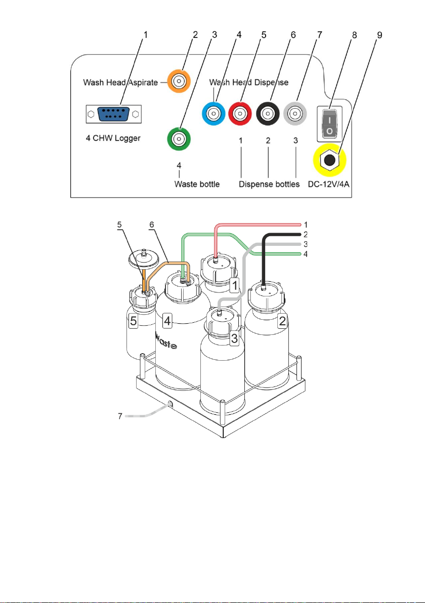
Figure 4. Rear panel
Figure 5. Bottles and tubing

Edition 3.03 11
4.3 Setup.
4.3.1 Place the unit on a strong horizontal surface, which can safely support weight of the
unit. To provide optimal ventilation, ensure 100 mm clearance on each side. Opera-
tion conditions are described in the Specification section.
4.3.2 Remove the protecting cover.
4.3.3 Unpack the plate platform (fig. 2/2).
4.3.4 Place the plate platform on the railing (fig. 3/1) so that the plate holder (flat spring)
faces the rear side of the unit (fig. 3/2). Magnet on the other side of the rail locks the
platform into start position.
Note.
If the plate platform is installed improperly, the magnet does not hold it in
place and the platform will be able tomove freely.Move the platform along
the railing until the magnets lock. Increase of resistance to movement in-
dicates that the magnets are locked.
4.3.5 Unpack the manifold.
4.3.6 Install the manifold in the slots of the holder arm (fig. 3/3). Magnets in the manifold
and the holder arm connect and align the manifold.
4.3.7 Connect the unit parts with the tubes as described below:
Note.
Each tube (fig. 2/6–2/8) and manifold (fig. 4/2–4/7) are colour-coded. En-
sure that the tubes are connected securely.
Tube
Connectable parts
Thin tube with a yellow
strip (fig. 2/7)
Wash head dispenser manifold, higher
and closer to display (fig. 3)
Yellow manifold Wash Head Dispense
on the rear panel (fig. 4/4)
Thin tube with a blue strip
(fig. 2/8)
Wash head aspiration, lower and far-
ther from display (fig. 3)
Blue manifold Wash Head Aspirate
on the rear panel (fig. 4/2)
Tube with a green strip
(fig. 5/4)
Central manifold on the 2L bottle #4
(fig. 5)
Green manifold 4 Waste bottle on the
rear panel (fig. 4/3)
Tube w/o strip
(fig. 5/6)
Side manifold on the 2L bottle #4
(fig. 5)
Side manifold on the 0.5L bottle #5
(fig. 5)
Short wide tube
(fig. 5/5)
Central manifold on the 0.5L bottle #5
(fig. 5)
Aspiration filter (fig. 2/13), side with the
marking IN
Tube with a red strip
(fig. 5/1)
Manifold on the 1L bottle #1 (fig. 5)
Red manifold 1 Dispense bottles
on the rear panel (fig. 4/5)
Tube with a black strip
(fig. 5/2)
Manifold on the 1L bottle #2 (fig. 5)
Black manifold 2 Dispense bottles
on the rear panel (fig. 4/6)
Tube with a white strip
(fig. 5/3)
Manifold on the 1L bottle #3 (fig. 5)
White manifold 3 Dispense bottles
on the rear panel (fig. 4/7)
4 CHW Logger adapter
cable (fig. 5/7, if in use)
4 CHW Logger connector on the rear panel (fig. 4/1)
4.3.8 Insert the manifold tube (fig. 3/2) into the valve opening (fig. 3/4). Press the valve in
the direction of the arrow and hold the valve while stretching the tube and pulling it
through the opening. Release the valve.
4.3.9 Install the protective cover. Ensure that all tubes are covered but are not squeezed.
4.3.10 Place the bottles near the unit. If 4 CHW Logger is in use, remove pads from under-
side of scale cups and place the bottles accordingly.

12 Edition 3.03
5. Operation
5.1 This section describes the following actions:
•Switching on and preparing the unit for operations.
•Microplate setup and unit calibration.
•Program choice and setup.
•Starting the chosen program.
5.2 Switching on.
Caution!
Before connecting the unit to the mainsoutlet, check that the power switch
(fig. 4/9) is in position O(off).
- Connect the external power supply to the power socket (fig. 4/8) on the rear panel
of the unit.
- Connect the power cord to the external power supply (fig. 2/16)
- Connect the external power supply to the grounded power socket.
- Position the unit with easy access to the plug and the power switch.
- Switch on the unit (position I) using the power switch (fig. 4/8) on the rear panel.
- When switched on, the unit performs full initialisation cycle and displays the mes-
sage” Power on reset” (figure 6)
Note.
Full initialisation cycle takes no longer than 5 seconds.
Figure 6. Initialisation screen
5.3 Before starting plate washing:
•Fill the rinsing liquid bottle #3 with distilled water or an appropriate cleansing solution.
•Fill the necessary bottles #1 and/or #2 with washing solutions.
5.4 Microplate installation. Hold the plate platform in place with one hand and place the
microplate on the plate platform on the other by pressing the flat spring on one side
of the platform.
Caution!
When installing a type of plate for the first time, perform the plate setup to
adjust the manifold lowering depth (see paragraph 4.20).
Note.
When working with the FastFRAME plates, remove the plate holder (fig.
3/2). Install it back after operations.
5.5 Program selection. All programs are divided into 5 categories with 10 programs
each. Each category corresponds to a different type of microplate and therefore, to a
different aspiration method (see figure 1):

Edition 3.03 13
•Category IPF96 U/V (1) is intended for U-shape and V shape well immunoplates.
•Categories IPF96 FLAT-2 (2) and IPF96 FLAT-C (3) are intended for flat-bottom well
immunoplates.
•Categories FastFRAME-2 (4) and FastFRAME-C (5) are intended for Watman
Schleicher & Shuell FastFRAME plates with rectangular wells.
Figure 7. Control panel keys Figure 8. Program selection
5.5.1 To navigate the menu:
•To select a row, press the Enter ▼key (fig. 7/4). Row selection is looped.
•To change the row value, use the + and –keys (fig. 7/6)
5.5.2 In figure 8, the user chose the first program (01) of the fifth type (FastFRAME). The
choice can be seen in the top right corner (5.1).
5.6 Changing the parameters of a program.
5.6.1 The manufacturer has pre-set parameters in each of the ten programs in each cate-
gory. Any parameter can be changed before selecting a program. Table 1 shows the
default program parameters. Table 2 shows the adjustable ranges and a description
of each parameter.

14 Edition 3.03
Table 1. Initial parameters of all user programs.
Parameter
Program number in the category
1
2
3
4
5
6
7
8
9
0
Dispense
YES
YES
YES
YES
YES
YES
YES
YES
YES
YES
Aspirate
YES
YES
YES
YES
YES
YES
YES
YES
YES
YES
Shake
NO
NO
NO
NO
NO
NO
NO
NO
NO
NO
Dispense rate
03
03
03
03
03
03
03
03
03
03
Aspirate rate
03
03
03
03
03
03
03
03
03
03
Soak time, s
-
30
30
30
30
30
30
30
30
30
Shaking time, s
-
-
-
-
-
-
-
-
-
-
Dispensed volume
-
350
350
350
350
350
350
350
350
350
Aspirat. time, s
1
1
1
1
1
1
1
1
1
1
Final aspirat., s
-
2
2
2
2
2
2
2
2
2
First aspirate
-
NO
YES
YES
NO
YES
YES
YES
YES
NO
Wash by rows
-
NO
YES
YES
NO
YES
YES
YES
YES
NO
On two channels
-
NO
NO
YES
NO
YES
YES
NO
NO
NO
Num.of wash cycles
1
1
5
5
1
3
5
7
7
5
The channel
1
1
1
1
1
1
1
1
1
1
Second chan. cycles
-
-
-
1
-
1
1
-
-
-
Second channel
-
-
-
2
-
2
2
-
-
-
Table 2. Program parameters and their definitions
Parameter
Value or range
Description
Dispense
yes/no
Perform fill
Aspirate
yes/no
Perform aspiration1
Shake
yes/no
Plate shaking on the platform during the cycle
Dispensing rate
01..03
Speed of liquid filling (100; 200; 300 μL/s)
Aspirating rate
01..03
Speed of liquid aspiration (100; 200; 300 μL/s)
Soak limit, s
0..300
Time between fill and aspiration (step 10 s)
Shaking time, s
05..150
Shaking time (step 5 s)
Dispensed volume
25..1600
Volume of dispensed liquid (step 25 μL)
Aspirat. time, s
200..3000 ms
Time of aspiration from well in cycle (step 200 ms)
Final aspirat., s
200..3000 ms
Time of last aspiration in the cycle (step 200 ms)
First aspirate
yes/no
Aspiration is the first action in a cycle
Wash by rows
yes/no
Each row is washed once per cycle
On two channels
yes/no
Use 2 washing solutions
Num. of wash. cycles
01..15
Number of washes with first solution
The channel
01..03
Number of bottle to use for the main washing
Second chan. cycles
01..15
Number of washes with second solution
Second channel
01..03
Number of bottle to use for the second washing
1
During aspiration, the waste fluid bottle is detected automatically –bottle #4. The number is not spec-
ified on the display

Edition 3.03 15
Note.
If some of the parameters from Tables 1 and 2 are set to NO, the associ-
ated items will not appear in the parameter change menu. For example,
Second chan. cycles and Second channelonly appear if On two channels
is set to YES.
5.6.2 To view the parameters of a program, press the Program Parameters key (fig. 7/3).
5.6.3 To navigate the parameters menu (figure 9):
•To select a row, use Rows ▲ and Enter ▼ keys.
•To change the value of a selected row, use + and –keys.
•To exit the parameter changing mode and save the changes, press the Program
parameters key again.
•To exit without saving, press the Esc key (fig. 7/5)
5.7 Running the program.
5.7.1 By default, the unit washes all rows of the microplate. In order to wash less rows,
when in the program selection menu (figure 8) press Rows ▲(fig. 7/1). Display
shows the row count menu (figure 10). Using the + and –keys, set the necessary
number of rows. To cancel and return to the previous menu, press Esc. To save and
start the program, continue reading.
Figure 9. Program parameters Figure 10. Row count selection menu
5.7.2 Press the Run/Stop key (fig. 7/7) to start the program. The program can be started
from the program selection menu, program parameters menu, or row count selection
menu (figures 8, 9, or 10). To abort and return to program selection, press Esc key.
5.7.3 If the operation requires washing on two channels (parameter On two channels set
to YES), then after starting the program, unit requests the confirmation of the correct
bottle number for second wash. (figure 11) Select the necessary bottle number using
+and -keys and press the Run/Stop key.
5.8 During operation.
5.8.1 During operation, display (figure 12) shows the program number (5.1), number of the
bottle in use (1), the current cycle (03) and the current timed action (Shake .. 05).
Figure 11. Second bottle confirmation Figure 12. Running program

16 Edition 3.03
5.8.2 If 4 CHW Logger, the 4-channel washing solution weight logger is connected to the
unit, then in addition to values on figure 12, display shows percentage of the remain-
ing volume of liquid in the bottles (figure 13). For the waste bottle #4, percentage
values will be increasing.
Figure 13. Running program with 4CHW Logger attached
5.9 To stop the program during operation, press the Run/Stop key. The message
CANCELLED BY OPERATOR appears on the lower line of the display. Press the
Run/Stop key to restart the operation.
5.10 When the cycle is completed, unit produces an informative sound signal. Proceed to
the section 6. Operation closedown.
Note.
If in doubt as to whether the rinsing is complete andeven, repeat the rinsing.
The quality of the plate washing affects the validity of the results obtained
from the test. To ensure that the washing procedure was performed cor-
rectly, make periodic visual checks of the reproducibility of the dispensed
volumes.
5.11 Plate setup. When installing a plate for the first time or when a plate of different
type is used, setup the lowering depth of the manifold’s needles.
•Press the Enter ▼ key in the start mode, then the Run/Stop key, and the following
message appears on the display (figure 14).
•To calibrate, press the Run/Stop key. The manifold measures the depth of the plate
well by touching the plate surface first and then the bottom of the well. The unit saves
the difference of the measured values.
Figure 14. Plate setup

Edition 3.03 17
6. Operation closedown
6.1 This section describes the required water rinsing procedures before shutdown.
6.2 Rinsing the tubes.
Caution!
Always perform the rinsing cycle using distilled water after finishing the
operation at the end of working day. This will help to keep the unit in work-
ing order and prevent tube clogging.
6.2.1 Fill one of the bottles ##1–3 with distilled water.
6.2.2 Attach the rinsible tube to this bottle.
6.2.3 Press the Prime rinse (fig. 7/2), display shows the rinsing menu (figure 15). Select
the channel of the attached tube using the +and –keys. Channel number can be
found on the rear panel of the unit, under the attached tube (fig. 4/5–4/7)
Figure 15. Rinsing the tubes, channel selection.
6.2.4 Press the Run/Stop key and the system will perform the rinsing cycle. Repeat the
procedure twice, if necessary.
6.2.5 Repeat steps 6.2.2–6.2.4 for the remaining tubes.
6.3 After finishing the operation, remove the tube from the valve opening (fig. 3/4) to
prevent deformation (wall gluing) of the dosing valve tube. To remove the tube, press
the valve on the side and stretch the tube a little when pulling it through the opening
(fig. 3/).
6.4 Switch the unit off using mains switch on the rear panel (position O, off). Unplug the
external power supply from the mains.
Caution!
Before transporting the unit at low temperatures, disconnect the tubes
from the buffer bottles and air-dry the tubes, following steps 6.2.2–6.2.4.
It is not necessary to carry out this procedure every time you finish oper-
ation of the unit.

18 Edition 3.03
7. Specifications
Theunitisdesigned foroperation incoldroomsandclosedlaboratory rooms atambient
temperature from +4°C to +40°C in a non-condensing atmosphere and maximum relative hu-
midity 80% for temperatures up to 31°C decreasing linearly to 50% relative humidity at 40°C.
Operating altitude above sea level is up to 2000 m.
Biosan is committed to a continuous programme of improvement and reserves the
right to alter design and specifications of the equipment without additional notice.
7.1 Dispense system of liquid dosage for each channel separately;
7.1.1 Minimum dispense volume ................................................................................25 µl
7.1.2 Maximum dispense volume ...........................................................................1600 µl
7.2 Dispense increment ..........................................................................................25 µl
7.3 Irregular liquid dosage at 300 µl ................................................max. ±2.5% or 7.5 µl
7.4 Allowed residual liquid volume in plate well ................................................max. 2 µl
7.5 Number of wells washed simultaneously .................................................................8
7.6 Number of washing cycles .................................................................................1–15
7.7 Aspiration time .................................................................................................1–3 s
7.8 Aspiration/dispensing speed .........................................................................3 levels
7.9 Washing buffers ......................................................................................3 maximum
7.10 Maximum number of washing liquids in program .....................................................2
7.11 Dispense system......................................................................................pinch valve
7.12 Soaking time ...................................................................0 –300 s (increment 10 s)
7.13 Shaking time ......................................................................0 –150 s (increment 5 s)
7.14 Number of washed rows ....................................................................................1–12
7.15 Time of plate single wash (350 µl) .............................................................max. 45 s
7.16 Number of programs .............................................................................................50
7.17 Plate platform and manifold movement ....................................................automated
7.18 Indication of operation modes ..................................................................8-line LCD
7.19 Dimensions .................................................................................. 375х345х180 mm
7.20 Weight, accurate within ±10% ...........................................................................11 kg
7.21 Operating voltage and current ...............................................................12 V=, 1.8 A
7.22 Power consumption........................................................................................... 22 W
7.23 External power supply.............................input 100–240 V~, 50/60 Hz, output 12 V=

Edition 3.03 19
8. Ordering information
8.1 Models and versions available:
Model
Version
Catalogue number
Inteliwasher 3D-IW8, microplate washer
V.3AW
BS-010212-AAA
8.2 To inquire about or order the optional accessories or the replacement parts, contact
Biosan or your local Biosan representative.
8.2.1 Optional accessories
Description
Catalogue number
4CHW Logger, 4-channel washing solution weight logger,
max. loading per scale cup 2 kg,
dimensions 267x252x97 mm, weight 3 kg (accurate within ±10%)
BS-060102-AAI
8.2.2 Replacement parts
Description
Catalogue number
Bottle #1, assembled (with weight, tube, filter)
BS-060102-S26
Bottle #2, assembled (with weight, tube, filter)
BS-060102-S27
Bottle #3, assembled (with weight, tube, filter)
BS-060102-S28
Bottle #4, assembled with tube
BS-060102-S29
Bottle #5, assembled (with filter, tube)
BS-060102-S43
Hydrophobic filter for bottle #5
BS-060102-S44
Filter complete set (filter, weight, tube)
BS-060102-S01
Silicone tube set, 6 pcs.
BS-060102-S39

20 Edition 3.03
9. Care and maintenance
9.1 Service.
9.1.1 If the unit is disabled (e.g., no aspiration, no reaction to key presses, etc.) or requires
maintenance, consult the error message and troubleshooting tables below, in 9.1.5
and 9.1.6. If the problem is not covered, disconnect the unit from the mains and con-
tact Biosan or your local Biosan representative.
9.1.2 All maintenance and repair operations (except listed below) must be performed only
by qualified and specially trained personnel.
9.1.3 Do not fit incorrect spare parts to the appliance. The manufacturer will provide all
necessary services, spare parts and subassemblies. To order the required services
and parts, contact your supplier.
9.1.4 Operating integrity check. If the unit follows the procedure described in sections 4. to
6., then no additional checks are required.
9.1.5 Error messages. Table below shows the program cycle error messages, their de-
scription and possible solutions that can be made by user.
Caution!
If the error message is not listed, copy the error text, unpowerthe unit and
forward the error text to Biosan or your local Biosan representative.
Table 3. Program error messages
Displayed message
Description
Solution
CANCELED BY OPERATOR
Program execution is stopped by operator.
Press Run/Stop key
BOTTLE 4 OVERFLOWED
Overflow of waste collection bottle.
Empty the bottle
BOTTLE ## EMPTY
Buffer bottle needs to be filled.
Fill the bottle
PLATE ERROR
Plate calibration is required.
See 5.11
9.1.6 Troubleshooting. Table 4 below lists some malfunctions that can be removed by the
user.
Caution!
If the problem persists or is not listed, unpower the unit and forward the
error text to Biosan or your local Biosan representative.
Table 4. Troubleshooting table
Symptom
Possible cause
Action required
Manifold dosing error. Volume of washing solution does not correspond to the set volume; dosing un-
evenness is observed along the plate wells, or the washing solution is not dispensed at all.
1. Poor contact between
the bottle hose connector
and the device
2. The hose is overbent
3. Obstruction of sieve fil-
ters
4. Obstruction of dispens-
ing channel of the manifold
or a needle
5. Absence of liquid in bot-
tles
1. Ensure proper connection of the bottle with the device.
2. Check if the hose is overbent and straighten it if necessary.
3. Check if the sieve filters in bottles No. 1, 2 and 3 are clogged.
4. Check if the dispensing channel of the manifold or needles is not ob-
structed. If yes, perform cleaning (see “Obstruction of dispensing channel
or a needle in the manifold” in this Table).
5. Ensure presence of liquid in the bottles No. 1, 2 and 3; fill up liquid in a
bottle if needed. (Attention: with 4CHW Logger, information on liquid lev-
els in bottles is shown on the display).
Other manuals for Inteliwasher 3D-IW8
1
Table of contents
Other Biosan Washer manuals


