BOLAB Systems 100-TS User manual
Operating Instructions
100-TS systems
Arbitrary 4-quadrant voltage or current amplifier
500 W / 1,000 W
Your contact:


BOLAB 100-TS Table of contents Page 3
Table of contents
1About these operating instructions....................................................................................... 5
1.1 Scope............................................................................................................................ 5
1.2 Copyright protection .................................................................................................. 5
1.3 Limitation of liability.................................................................................................... 6
2Representation conventions .................................................................................................. 7
3Safety ........................................................................................................................................ 9
3.1 General safety advice ................................................................................................. 9
3.2 Safety instructions for parallel operation................................................................ 10
3.3 Intended use..............................................................................................................10
3.3.1 Hardware ............................................................................................................10
3.3.2 Software.............................................................................................................. 10
3.3.3 Users....................................................................................................................11
4Transport and storage ..........................................................................................................12
5Scope of delivery...................................................................................................................13
6Basic device information ......................................................................................................14
6.1 General device description......................................................................................14
6.2 Protection mechanisms (protections) .....................................................................14
6.3 Voltage ranges .......................................................................................................... 15
6.4 4 quadrants ................................................................................................................16
6.5 Basic set-up................................................................................................................17
6.6 Ground and potentials .............................................................................................17
7Device/component description...........................................................................................19
7.1 Front of the device .................................................................................................... 19
7.1.1 Component description - front ........................................................................ 19
7.2 Back of the device .....................................................................................................23
7.2.1 Connections for 3 HE devices ..........................................................................23
7.2.2 Connections for 4 HE devices ..........................................................................25
7.2.3 Component description - back........................................................................ 26
7.3 Detailed description of components ......................................................................31
7.3.1 Analogue outputs..............................................................................................31
7.3.2 Analogue inputs ................................................................................................33
7.3.3 Digital inputs/outputs ....................................................................................... 35

BOLAB 100-TS Table of contents Page 4
7.3.4 Counter inputs/outputs ....................................................................................42
7.3.5 Interlock .............................................................................................................. 43
7.3.6 AUX IN ................................................................................................................44
7.3.7 Bridge .................................................................................................................46
7.3.8 Sense (optional) .................................................................................................47
7.3.9 Signal IN.............................................................................................................. 47
8Installation ..............................................................................................................................49
8.1 Setting up the device................................................................................................49
9Using the device for the first time........................................................................................ 50
9.1 Safety .......................................................................................................................... 50
9.2 Connecting the mains cable .................................................................................... 50
9.2.1 Connecting a device to the power supply...................................................... 51
9.3 Connecting an external signal source ....................................................................51
9.4 Commissioning of voltage amplifier operating mode ......................................... 51
9.4.1 Connecting the load .........................................................................................52
9.5 Commissioning of current amplifier operating mode ..........................................53
9.5.1 Performing a load test....................................................................................... 53
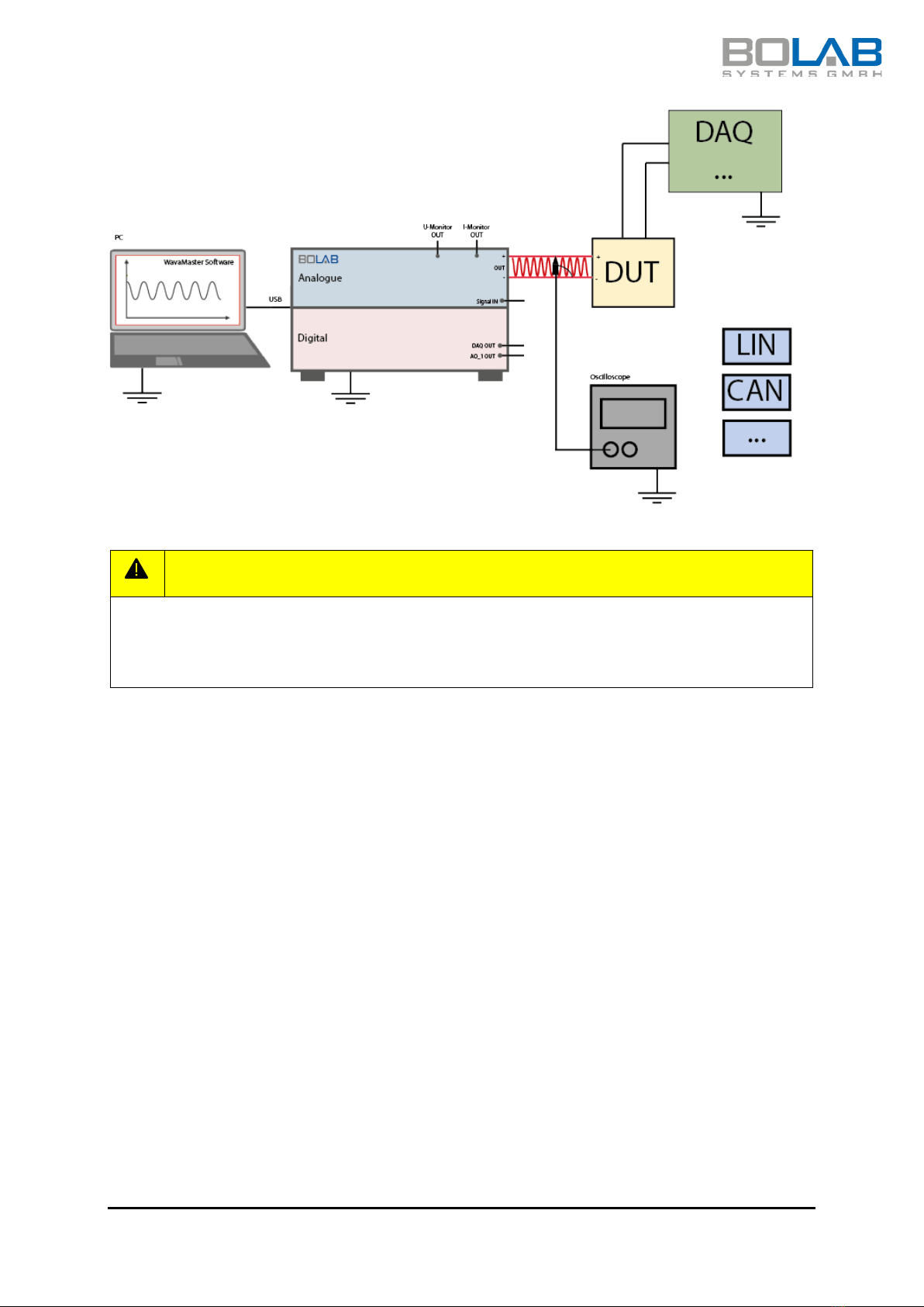
10 Automated test systems and environments ....................................................................... 55
11 Device drawings .................................................................................................................... 56
11.1 Front 4 HE .................................................................................................................. 56
11.2 Transverse side 4 HE................................................................................................. 56
11.3 Front 3 HE .................................................................................................................. 57
11.4 Transverse side 3 HE................................................................................................. 57
12 Technical data........................................................................................................................ 58
12.1 N-TS / 500 W - 1,000 W ............................................................................................ 58
12.2 100-35R-TS / 500 W - 1,000 W ................................................................................ 59
12.3 100-70N-TS / 500 W – 1,000 W ............................................................................... 60
12.4 100-70R-TS / 500 W – 1,000 W ................................................................................ 61
12.5 100-75N-TS / 500 W – 1,000 W ............................................................................... 62
13 Troubleshooting....................................................................................................................64
14 Maintenance .......................................................................................................................... 65
14.1 Calibration..................................................................................................................65
15 Cleaning and Care ................................................................................................................ 66
16 Recycling/Disposal/Environmental Protection .................................................................. 67

BOLAB 100-TS About these operating instructions Page 5
1About these operating instructions
1.1 Scope
These operating instructions cover the following amplifier systems (hereinafter referred to
as the 100-TS series):
-16 V … +35 V -16 V … 70 V -75 V … +75 V
105-35N-TS 105-70N-TS 105-75N-TS
110-35N-TS 110-70N-TS 110-75N-TS
-32 V … +35 V -32 V … +70 V
105-35Q-TS 105-70Q-TS
-30 V … +35 V -30 V … 70 V
105-35R-TS 105-70R-TS
110-35R-TS 110-70R-TS
1.2 Copyright protection
These operating instructions may not be reproduced in any form, even in the form of
extracts, without the written permission of BOLAB Systems GmbH, in accordance with DIN
EN 16016.
We reserve the right to make technical changes at any time, especially if these changes
improve the performance of the product.
© Copyright 2022
BOLAB Systems GmbH
Mühlstetten 3
D-72351 Geislingen
Germany
Tel.: +49 74 28 / 94 52 42 – 0
Fax: +49 74 28 / 94 52 42 – 20
E-mail: info@bolab-systems.de
Web: www.bolab-systems.com

BOLAB 100-TS About these operating instructions Page 6
1.3 Limitation of liability
The information in these operating instructions should always be follow when handling the
device. This applies to the operation, maintenance and repair of the 100-TS series. Failure
to comply with such instructions or warnings in these operating instructions is a violation of
the safety standards for the respective area of application. We shall not be responsible for
consequences that result from non-compliance with instructions and warnings.
BOLAB 100-TS Representation conventions Page 7
2Representation conventions
These instructions contain recurring representation elements that reflect the function of
certain information:
DANGER
Indicates an immediately dangerous situation that, if not avoided, will result in death or
serious injury.
WARNING
Indicates a potentially dangerous situation that, if not avoided, may result in death or
serious injury.
CAUTION
Indicates a potentially dangerous situation that, if not avoided, may result in minor or
moderate injury or damage to property.
ADVICE
Indicates important information about the product or actions that should be taken into
account for the correct functioning of the device.
One or more words in bold represent a term that is also found on the product.
1. Instructions with a fixed sequence are displayed in a numbered list.
Results or outcomes of these actions are shown by “”.
BOLAB 100-TS Representation conventions Page 8
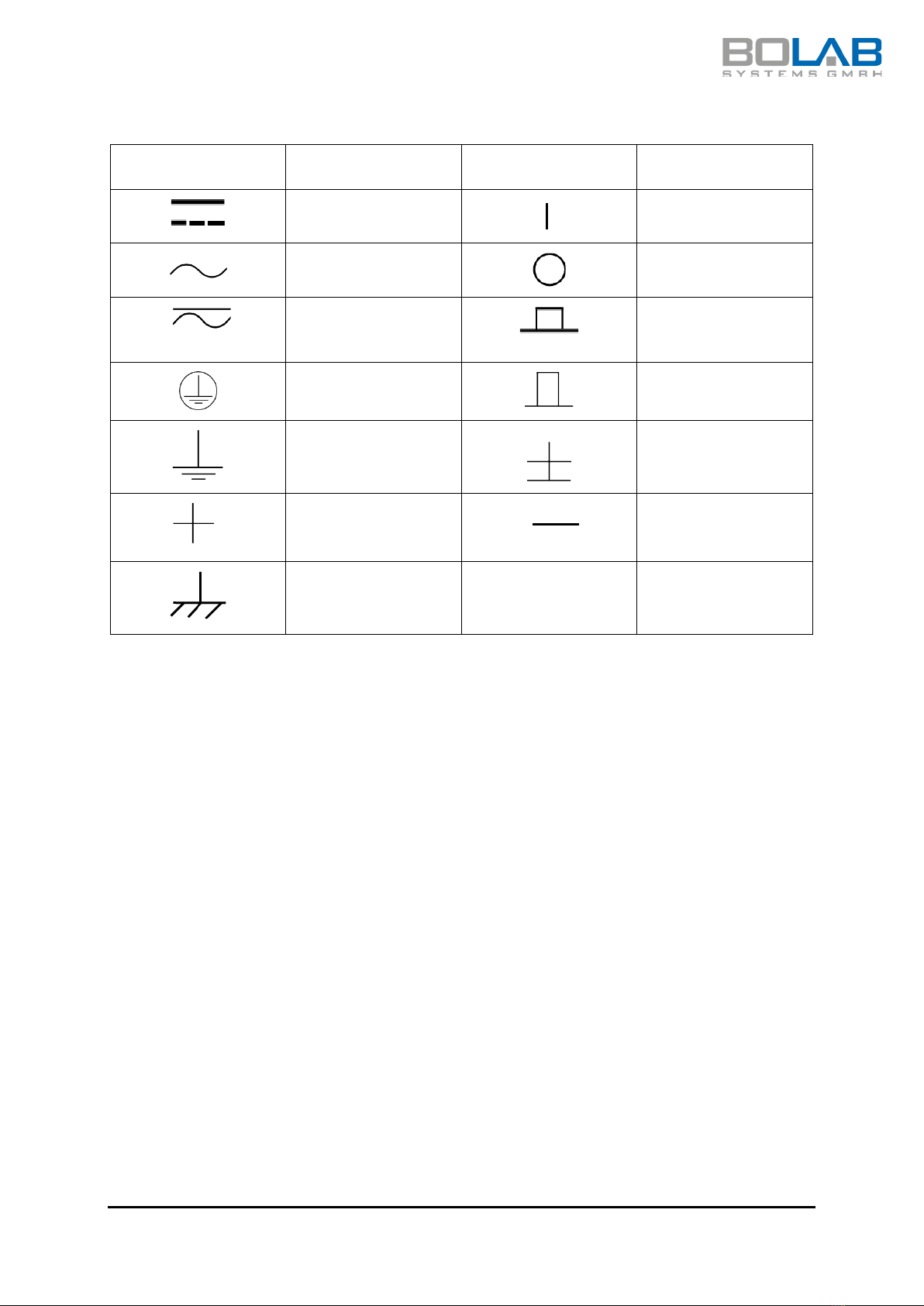
Other icons
Icon Meaning Icon Meaning
Direct current ON
Alternating current OFF
AC and DC Operating voltage
on
Protective earthing
Operating voltage
off
Ground terminal
Reference terminal
Positive terminal
Negative terminal
Ground
BOLAB 100-TS Safety Page 9
3Safety
3.1 General safety advice
Important information
•These operating instructions are intended for qualified staff who are
familiar with the set-up, commissioning and operation of the described
devices.
•The device must only be used by suitably qualified staff.
•Read the documentation carefully.
•Use the device only according to this documentation.
•Note the advice and icons on the product.
•Keep the documentation for future reference.
•Share the documentation with later users.
•Keep the documentation available near the system at all times.
•Also refer to the documentation for additional components used.
•The correct and safe operation of the device depends on proper
transport, storage, installation and maintenance.
Danger due to operation despite a defect
Do not use the device:
•if the device has visible damage or deformations
•if the appliance is no longer working properly
•if the device has been overloaded with excessive currents (e.g. short-
circuit)
•if the device has been overloaded with excessive voltages
•if the device has been connected to too high a supply voltage
•if there are loose parts in the device
•after condensation due to severe temperature fluctuations
Danger from electric voltage
•When working with electrical equipment, certain parts may be under
dangerous voltage. Failure to observe the warnings in these operating
instructions may result in serious personal injury or damage to
equipment.
•The device complies with protection class I. Only operate the appliance
with the supplied 3-wire mains cable with a protective earth.
•Only connect the device to a grounded electrical outlet.
•The corresponding fuse must be dimensioned to fit the device.
•Avoid the device coming into contact with liquids or moisture.
•Before installing, cleaning, maintaining, or repairing the device, turn it
off completely.
•Do not clean the device in running water or by immersing it in liquid.

BOLAB 100-TS Safety Page 10
Proper handling
•Do not make any modifications to the device.
•Do not allow operators to remove the housing.
•Do not use the device if covers are removed or loose.
•Check the device regularly for damage. If damaged, switch off the
device and disconnect it completely from the power supply. Contact
Customer Service or the dealer.
•Maintenance and repair are reserved for qualified service staff.
•Keep the air vents uncovered.
Fire hazard
•Do not use the device near flammable gases, vapours or dust.
3.2 Safety instructions for parallel operation
•Before operating devices and systems in parallel or in series, clarify with
the manufacturer which combinations are permitted.
•Wire the entire amplifier system prior to operation, carefully following
the wiring instructions (see figures below) and cable specifications to
ensure stable signal processing.
•Ensure an adequate and reliable mains supply.
•Allow the amplifier to warm up for 30 minutes to stabilise operating
points.
•To reduce the power dissipation of the amplifier, the operating voltage
should always be selected according to the load.
•The current output can produce high voltages that are dangerous for
life.
3.3 Intended use
3.3.1 Hardware
The device may only be operated within the technical specifications.
Modifications to the device are not permitted without the consent and approval of the
manufacturer. This documentation is part of the device and must be available at all times.
Comply with all the safety regulations that are detailed in this documentation.
Improper use invalidates any liability claims.
3.3.2 Software
The BOLAB WaveMaster software is a computer program developed to remotely control
and configure BOLAB power amplifiers. Observe the specified data and applications

BOLAB 100-TS Safety Page 11
described in these instructions. Changes to the program are not permitted without the
consent and approval of the manufacturer. Smooth and safe operation of the software
requires proper installation and careful operation. These operating instructions are part of
the software and must be available at all times. Comply with all the safety regulations that
are detailed in this documentation.
3.3.3 Users
Operation may only be carried out by qualified persons who have received additional
hardware and software training from BOLAB in addition to these instructions. Alternatively,
the user licence can be obtained via the completed BOLAB eLearning course. Permission
is granted by means of a certificate which is issued following the eLearning course.
Qualified persons within the meaning of the safety information in this documentation are
those who are authorised to commission and operate systems in accordance with the
safety technology standards.
BOLAB 100-TS Transport and storage Page 12
4Transport and storage
CAUTION
Do not drop the device, use it as a storage surface, or expose it to strong mechanical
pressure. The effects can damage the device. Only store the device in dry places and as
airtight as possible.
CAUTION
Do not use the front or rear handles to carry the device. The handles are only used for
inserting or removing the device from a 19” cabinet.
CAUTION
Use the supplied or appropriate packaging material for storage and transport. In order
to lift the device, hold it by the housing with both hands.
BOLAB 100-TS Scope of delivery Page 13
5Scope of delivery
ADVICE
Check the package contents for completeness after unpacking. Keep the packaging for
future transport, e.g. for annual calibration.
Check the device for visible damage.
Report any transport damage to the carrier and the supplier immediately.
Number/component Description
1 Amplifier
1 Mains cable
1 USB cable
1 Operating Instructions

BOLAB 100-TS Basic device information Page 14
6Basic device information
6.1 General device description
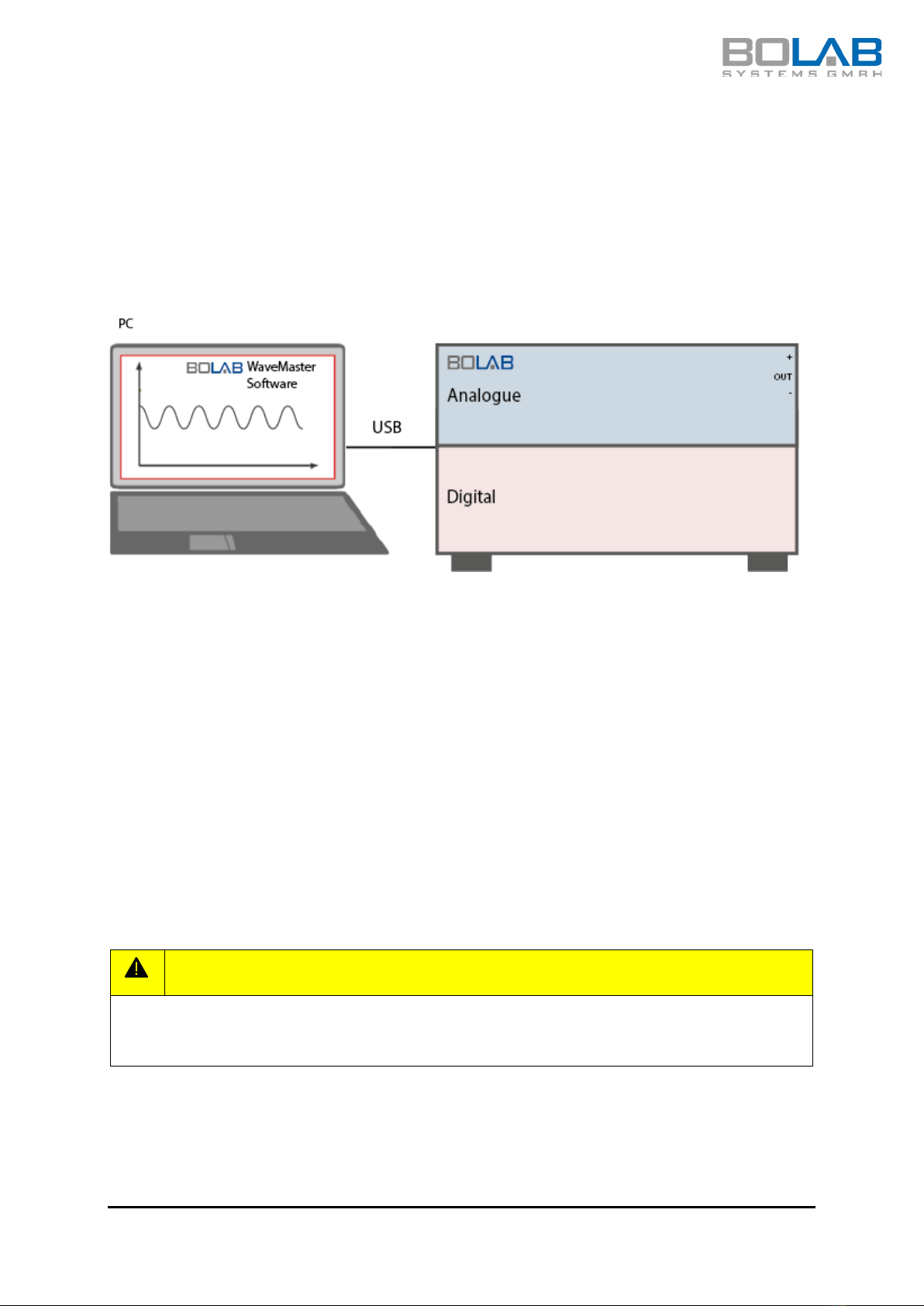
The BOLAB 4-quadrant amplifier systems are a new generation of analogue amplifiers in
combination with a built-in digital control and data acquisition unit. The associated BOLAB
WaveMaster software allows simple and intuitive creation and generation of almost any
waveform sequence. These waveform sequences are transferred to the analogue amplifier
section via the integrated control section. The built-in USB interface transmits device
control commands, generated waveform signals as well as voltage and current signals
measured in the amplifier system.
The amplifier system offers a variety of device functions and features. The main features
are rise and fall speeds of up to 100 V/µs, lowest overshoot and undershoot for fast signal
changes, digital inputs and outputs for system integration in automation equipment and
analogue inputs for synchronous data acquisition.
6.2 Protection mechanisms (protections)
The device has protective mechanisms (protections) which are used to protect the device
from defects. Protections are triggered when system limits are exceeded and result in a
safety shutdown.
ADVICE
When a protection is triggered, this is indicated by the protection LED on the front.
There are defined time, voltage, current, power dissipation, and temperature limits that
are continuously monitored by the device to protect the system.
CAUTION
Do not continue if a protection is triggered on the system. The problem must be
analysed and resolved first.
Reasons for triggering protection may include:
•Overvoltage
•Overcurrent
•Power-on peak current
•Overvoltage protection
•Excessive power dissipation
•Overheating
•Hardware defective
BOLAB 100-TS Basic device information Page 15
6.3 Voltage ranges
The BOLAB 4-quadrant amplifier has three different voltage ranges. There is one Low, one
Middle and one High voltage range. These ranges are identified by the Mid and High
buttons on the front of the device. The individual voltage ranges can be found in the
technical information for the respective amplifier system.
Neither of the two buttons is selected initially when the 4-quadrant amplifier is turned on.
This means that the device is working in the Low voltage range. Switching to the middle or
upper voltage range is done with the front buttons or via the BOLAB WaveMaster
software:
• high operating voltage for high output voltages and low load currents
• middle operating voltage for middle output voltages and middle load currents
• low operating voltage for low output voltages and high load currents
CAUTION
Switching to a different voltage range may only be carried out with a voltage-free
output. Manual switching is not allowed while using the WaveMaster software.
To keep the power dissipation of the amplifier low, the operating voltage must always be
selected according to the load.
ADVICE
Refer to the technical specifications of these operating instructions for the available
operating voltage ranges.
Voltage ranges using the example of a BOLAB 105-70N-TS:
Total voltage range: -16 V to +70 V
Voltage range Low: -16 V to +16 V
Voltage range Mid: -16 V to +27 V
Voltage range High: -16 V to +70 V

BOLAB 100-TS Basic device information Page 16
Figure 1: Voltage ranges
In the Low voltage range, the amplifier system has the maximum current capacity. This
current capacity is lower in the Middle voltage range than in the Low voltage range. The
same applies to the High voltage range.
6.4 4 quadrants
The BOLAB amplifier systems work in all 4 quadrants. Depending on the load or the
control voltage specification, the systems work in the respective quadrant.
Figure 2: 4 quadrants
Source
Source
Sink
Sink
BOLAB 100-TS Basic device information Page 17
The amplifier systems have different performance data in the different quadrants. The
performance in each quadrant is different. The source power is higher than the sink
power. If necessary, ask the manufacturer for the performance data for your amplifier
model. Additional and detailed explanations of the working methods in all 4 quadrants
can be found in the BOLAB eLearning course.
6.5 Basic set-up
6.6 Ground and potentials
There are some important rules that must be strictly followed. Different ground potentials
in the system configuration, along with the amplifier system, the DUT and all connected
components, such as data acquisition systems, oscilloscopes, communication buses etc.,
lead to oscillations at the amplifier output. Always be aware of where the potentials are for
these individual components. Ensure that there is no potential. The amplifier system tries
to compensate any potential differences at high speed due to its characteristic as a source
or sink system. This leads to oscillations at the amplifier output. These oscillations quickly
exceed the permitted limits for the respective voltage ranges up to which the amplifier is
protected. These fluctuations at the output also cause the amplifier to heat up. Extended
oscillation and exceeding the permitted voltages at the amplifier output lead to
overheating, or cause the permitted voltage limits to be exceeded for components within
the amplifier system and thus lead to the destruction of the system.
CAUTION
If you do not observe these and the following rules, no warranty claims may be asserted
in the event of a device fault or destruction.
BOLAB 100-TS Basic device information Page 18
Figure 3: Oscillation at the amplifier output
CAUTION
Only use individual active probes or differential probes for each individual channel if
you are measuring at the main output of the system with e,g, an oscilloscope or data
acquisition unit.

BOLAB 100-TS Device/component description Page 19
7Device/component description
7.1 Front of the device
Figure 4: Front of the device
1. Protection LED
6. Output on/off button
2. DAQ status LED
7. Button for operating mode
3. High operating voltage button
8. Ready LED
4. Button for middle operating voltage
9. Positive and negative outputs
5. On/Off toggle switch
10. Grounding connection
7.1.1 Component description - front
7.1.1.1 Protection LED:
If a protection threshold is unduly exceeded, the protection LED indicates the activation of
the protection mechanism:
•LED lights up red:Shutdown due to overtemperature. As soon as the temperature
has dropped, the device switches on again automatically.
•LED flashes slowly (~1/s) red:
oShutdown because the permissible overvoltage has been exceeded.
oShutdown because the overcurrent limit has been exceeded.
oShutdown because a maximum power-on peak current has been exceeded.
oShutdown because the voltage measured at the amplifier output has been
exceeded.

BOLAB 100-TS Device/component description Page 20
oShutdown because the maximum permissible power dissipation has been
exceeded.
After 10 seconds, the LED goes out and the device is ready for use again. Before
continuing to work with the device, the cause must be analysed and corrective
action taken to prevent repeated triggering of the protection.
•LED flashes quickly (~3/s) red: Hardware is defective. Contact the Customer
Service of BOLAB Systems GmbH.
7.1.1.2 DAQ status LED:
Shows whether a waveform is currently running:
•LED lights up red: Internal voltage or current waveform is output.
•LED is off: no waveform is running.
7.1.1.3 High operating voltage button (Supply Voltage High):
Activates the High operating voltage:
•LED in the button lights up orange: Middle operating voltage is active.
•LEDs of the middle and high operating voltage buttons are both off: low
operating voltage is active.
7.1.1.4 Button for middle operating voltage (Supply Voltage Mid):
Activates the middle operating voltage:
•LED in the button lights up orange: middle operating voltage is active.
•LEDs of the middle and high operating voltage buttons are both off: low
operating voltage is active.
7.1.1.5 On/Off toggle switch (POWER):
Switches the device on or off:
•Toggle switch on I icon: Device is switched on.
•Toggle switch on 0 icon: Device is switched off.
7.1.1.6 Output On/Off button:
Switches the state of the output on or off:
•LED in the button lights up green: Output is active (low impedance)
•LED in the button is off: Output is inactive (high impedance)
7.1.1.7 Operating mode button (Current Mode):
Controls the change of operating modes:
•LED in the button lights up orange: Current amplifier operating mode
Table of contents


