Bolide Technology DR-8000 User manual

Before use theproduct, please readthismanual carefully.
DR-8000 VideoSwitchingMatrix
Installation Manual

Index
1. Preface..................................................................................................................................1
2.Feature..................................................................................................................................2
3.Specification.........................................................................................................................2
4.Systemstructure...................................................................................................................3
4.1Mechanism features....................................................................................................................................3
4.2Modulesfunctions description....................................................................................................................3
4.3System schematic figure.............................................................................................................................4
5. DR-8000component modules andexpansion................................................................5
5.1Single bayconfiguration.............................................................................................................................5
5.2Twobaysconfiguration..............................................................................................................................5
5.3Three baysconfiguration............................................................................................................................6
5.4Fourbaysconfiguration..............................................................................................................................6
6. DR-8000 matrixinstallation...........................................................................................7
6.1DR-8000 matrixstructure..............................................................................................................................7
6.2Motherboard............................................................................................................................................9
6.3Powersupplymodule................................................................................................................................11
6.4Controlboard............................................................................................................................................13
6.5Control outputconnectionboard................................................................................................................16
6.6Videoinputswitchingboard......................................................................................................................17
6.7Video input connectionboard....................................................................................................................20
6.8Videooutput characterscreenoverlayboard..............................................................................................21
6.9Videooutput connectionboard..................................................................................................................24
7.DR-8000 matrixsystem................................................................................................25
7.1DR-8000 matrix system scamera connection...................................................................................... 25
7.2DR-8000 matrixsystem smonitorconnection.......................................................................................26
7.3DR-8000single baymatrix systemapplication......................................................................................27
7.4DR-8000matrixanalog/digital combinationapplication........................................................................28

DR-8000 VideoSwitchingMatrix
-1-
Preface
Thismanualillustrates theinstallationand operation ofDR-8000 videoswitchingmatrix system. DR-
8000 is amulti input/output channels CCTVsurveillanceswitching system.Video inputsignal cancomefrom
local/remotecameraor other videosources,andvideooutputcango to monitor orDVR etc. Videoconnection
shouldcomply to 75 ohmimpedance.
DR-8000 consists of power supplymodule,centralcontrol module, datareceiving/buffer module, VIM
(videoinput module),VOM(videooutputmodule)andtheir correspondingbackboards.
DR-8000 could workindependentlyor expand up to4 bayswhen lager volumeis needed.
Inaddition tovideoswitching function, DR-8000 canlink to variousaccessorieslikealarminput box,
alarmoutput box, multi-function keyboard, RS485 distributor, PC, etc.DR-8000 s dimensionis fit tointerna-
tional standardrack. It s schematicconnectionfigureis as below:
Picture 1. DR-8000 schematicconnectionfigure

DR-8000 VideoSwitchingMatrix
-2-
Feature
1. ModularizedMPU and high compact configuration.
2. Ethernet port technology, onlineand remotecontrol.
3. Videoinput and video output support hotswap.Facilitatetheinstallation and maintenance.
4. Singlematrixbayconfiguration: Max272 videoinputs; 64 videooutputs
Max input setup: 272X16; Max outputs setup: 224X64
5. Four matrixesbayconfiguration: Max 1024videoinputs;64videooutputs.
6. Independent internal video; Chineseand Englishmenus; ChineseandEnglishcameratitlesand state
displays.
7. Powersyncswitch:AdjustableSyncphase(multipleof60degree):Convenientcircuit.
Specification
lPower supply:AC220V/50HzorAC110V/60Hz
lInputSignal:1V Peak-to-Peak,InputImpedance:75 Ω)
2V (Peak-to-Peak,Input Impedance:High)
lInput Impedance:High or 75 Ω
lOutputSignal:2V Peak-to-Peak,OutputImpedance:75 Ω)
lOutput Impedance:75 Ω
lInsertGain:±0.5dB
lS/NRatio Weighted): ≥52dB
lAdjacent ChannelIsolation Degree Inputto Input):≥50 dB
lAdjacentChannelCrosstalk Input toOutput):≥ 40 dB
lFrequencyCharacteristics -3dB Bandwidth): 50Hz ∽12MHz
lDCVoltage VideoSignal): About-0.4V ∽-0.6V;
lKB/Receiver Controlling Time: ≤20ms(Typical)
lSwitch:Complete switching ofcross-point matrix
lSwitchSpeed:SyncSwitch ≤20ms PAL),≤ 16.70ms(NTSC)
lVideoInput:BNCJack,16 ∽1024VideoInputs
lVideoOutput:BNCJack,16 ∽64VideoOutputs
lRS232 Interface:OneRS23Local PCInterface
lBaudRate:9600bps、19200bps、38400bps、76800bps
lEthernetInterface:1Mbytes—2Mbytes/sCommunicationSpeed
lOSDDisplay:Date/Time, MonitorTitle,CameraNoand Title,etc
lCharacter:Chinese:National Band-1 WordStorage;EnglishIn Common Use
lSyncSwitch:PowerSync
lData:Settings and configuration datacanmaintainat least 5 years
lDimension:312 mm H)X483 mm W)X470 mm D)
lWeight:30Kg

DR-8000 VideoSwitchingMatrix
-3-
Systemstructure
nMechanism features
lFor 19 inchEIA rack;
lSinglebaydimension:312 H)X483 W)X470 D)mm H:7U);
lModularizedMPUand high compact configuration;
lConnect accessoriesviaEthernet RJ-45 port. e.g.alarminput box, alarmoutput box, keyboard,
RS485 distributor, etc)
lConnect PC viaRS232 port;
lSpecial,internal video, BNCchannel for programmingmonitor;
lRJ-45 port for internalcontroldatabus.
lThesystemcontainsthefollowingmodules:
a)Motherboard with64channelsvideobusand internalcontrolbus)。
b ) Standardindustrial 24V switchingpower supply module
c)Controlboard
d)Controloutput connection board
e)Videoinput switchingboard withCPU,nocharacteroverlay )。
f )Videoinputconnection board SurgeandEMCprotection;impedancesselection;video
looping socket)。
g )Videooutputcharacterscreenoverlayboard withinput/outputbuffer)。
h )Video outputconnectionboard SurgeandEMC protection;videoloopjack)。
nModules functionsdescription
lMotherboard
It has18standard slotsand2special slots.Standardslotsarefor Videoinputswitching boar,
Videoinputconnection board, Video output characterscreenoverlay boardand Videooutput connec-
tionboard,each boardhasits own uniqueID. It can accept 1-17 videoinputmodules(16-272 channels),
1-4video output modules 16-64channels).Special slotsarefor Control boardandControloutput
connectionboard.
lPowersupplymodule
Standardindustrial24Vswitchingpowersupplymodule 24V/6.25A150W),self adaptive
for220V/50Hzand 110V/60Hz. There aresecond+5V/-5DC/DC poweradaptersineach
function modules for enhancing system reliability.
lControl board
a)Withindependentpowersupplymodule DC/DC,input24V,output 5V,-5V);
b) Characterdisplay:Chinese andEnglish
c)Communicates withotheraccessoriesanddevicesvia Ethernet.
d)Autoassign IPfor peripheral device,e.g. keyboards, distributors, alarmboxes etc.
e)RS-232:supportRS-232 communication;
f)RS-485:internal RS485buscontrol
lControl output connectionboard
This modulehas 1 Ethernet RJ45 port, 1 systemcontrolbus RJ45 port, 1 RS232 port forPCand 1

DR-8000 VideoSwitchingMatrix
-4-
BNC jackfor systemsetting. Italsohas power synchronization signal generator and 10M networkcard
transformer;
lVideo inputswitching board
a)Withindependentpowersupplymodule DC/DC,input24V,output 5V,-5V);
b) Independent SingleChip Microcomputer control;
c)16X64 fullcross matrix switching;
d)Module IDand function DIPsetting
e)Videolossdetection
lVideoinputconnectionboard
This module has16 videoinputBNCjackswithimpedance selection DIP high or75 Ω),
surgeproof grade1, 500V)andEMIprotection, 16channelsvideoloopingsocket.
lVideo outputcharacter screenoverlay board
a)Withindependentpowersupplymodule DC/DC,input24V,output 5V,-5V);
b) Independent SingleChip Microcomputer control;
c)Chinese/ English characters screenoverlayfunction
d)16X64 fullcross matrix switching;
inputbus:64 channels,select16 channel according slot ID;
outputbus:16 channels。Output standardvideosignalwithcharacteroverlay;
e)Module IDand function DIPsetting
lVideooutput connectionboard
This modulehas16 videoinput BNC jacks, surgeproof grade1, 500V)andEMIprotection.
nSystem schematicfigure
Picture2, Systemschematicfigure
Videoinput
connection
board
Videoout-
putconnec-
tionboard
Videoout-
putconnec-
tionboard
Controloutput connection
board
lRS232 port
lEthernet port
lInternal system control bus
Control board
Setting menu
System control
Configuration data
Internal system control bus
24V switching
powersupply
Videoinput
switching
board
Video input
switching
board
Videooutput
character
screenover-
layboard
Video output
character
screenover-
layboard
Motherboard
l64 channels video output bus
lInternal system control bus
lDC 24V power
Videoinput
connection
board
14 4
14 4

DR-8000 VideoSwitchingMatrix
-5-
DR-8000 componentmodules andexpansion
Onematrix systemcanconsist of 1 to4 DR-8000 matrix. Thefollowing arethenames for DR-8000
component modules.
01-------------------------- Mother board
02-------------------------- Standardindustrial 24Vswitching power supplymodule
03-------------------------- Control board
04-------------------------- Control outputconnection board
05-------------------------- Videoinputswitchingboard
06-------------------------- Videoinputconnection board
07-------------------------- Videooutput characterscreenoverlayboard
08-------------------------- Videooutputconnection board
09--------------------------Expansion board
nSinglebayconfiguration
OneDR-8000 has 1 power supply, 1 pair specialslots,18 pairs standardslots. Usercanuseany pairof
standardslots, but pleasemakesureeachboardis withitscorresponding board.Singlebayconfiguration is
shown below:
Table1 Singlebayconfiguration
nTwo baysconfiguration
Two DR-8000bayssystemhas 2 power supply, 1 pair special slots, 36 pairs standard slots. User canuse
any pairof standardslots, but pleasemakesureeachboardis withits correspondingboard. Eachbayneeds
anexpansionmodule.Twobays configuration is shownbelow:
Table2 Two bays configuration
11111
21111
31111
41111
51-141-151-161-17
61-141-151-161-17
71-41-31-21
81-41-31-21
input16-22416-24016-25616-272
output16-6416-4816-3216
Modulequantity
Module
number
volume
12222
22222
31111
41111
517-3017-3117-3217-33
617-3017-3117-3217-33
71-4 1-3 1-2 1
81-4 1-3 1-2 1
92222
Input272-480272-496272-512272-528
Output 16-64 16-48 16-32 16
Modulequantity
Module
number
volume

Index
1. Preface..................................................................................................................................1
2.Feature..................................................................................................................................2
3.Specification.........................................................................................................................2
4.Systemstructure...................................................................................................................3
4.1Mechanism features....................................................................................................................................3
4.2Modulesfunctions description....................................................................................................................3
4.3System schematic figure.............................................................................................................................4
5. DR-8000component modules andexpansion................................................................5
5.1Single bayconfiguration.............................................................................................................................5
5.2Twobaysconfiguration..............................................................................................................................5
5.3Three baysconfiguration............................................................................................................................6
5.4Fourbaysconfiguration..............................................................................................................................6
6. DR-8000 matrixinstallation...........................................................................................7
6.1DR-8000 matrixstructure..............................................................................................................................7
6.2Motherboard............................................................................................................................................9
6.3Powersupplymodule................................................................................................................................11
6.4Controlboard............................................................................................................................................13
6.5Control outputconnectionboard................................................................................................................16
6.6Videoinputswitchingboard......................................................................................................................17
6.7Video input connectionboard....................................................................................................................20
6.8Videooutput characterscreenoverlayboard..............................................................................................21
6.9Videooutput connectionboard..................................................................................................................24
7.DR-8000 matrixsystem................................................................................................25
7.1DR-8000 matrix system scamera connection...................................................................................... 25
7.2DR-8000 matrixsystem smonitorconnection.......................................................................................26
7.3DR-8000single baymatrix systemapplication......................................................................................27
7.4DR8000matrixanalog/digital combinationapplication........................................................................28

DR-8000 VideoSwitchingMatrix
-7-
DR-8000 matrix installation
ItisrecommendedtoinstallDR-8000matrix in19 inchstandard rack. Pleasedonotleaveany
thing blocktheventilation holes, otherwisethematrix maybecomemalfunctioned becauseof overheat.
nDR-8000matrixstructure
Picture3 DR-8000 matrix front view
Picture4DR-8000 matrix backview

DR-8000 VideoSwitchingMatrix
-8-
Picture5 DR-8000 matrix mother boardview
01, Mother board
02,Standardindustrial 24Vswitching powersupplymodule
03, Control board
04, Control outputconnectionboard
05,Videoinputswitchingboard
06,Videoinputconnectionboard
07, Videooutputcharacterscreenoverlayboard
08,Videooutput connection board
09,Powerinput jack
10, Power wires
11,Powerswitch
12,Powersocket
13, Front cover
14, Backcover
15,Connection bridge
Everyboardshouldbeinstalled through theslot and connect tothemotherboardand thecorrespond-
ingboardshould beinstalledat theoppositeside.(refer to blowtableto findout boardsandtheir corre-
sponding boards). Therearetwoirremovablescrewson eachboardtofix theboardon thematrix.

DR-8000 VideoSwitchingMatrix
-9-
Table 5corresponding board
lMatrix frontside
Motherboard,power supply module, Frontcover,Controlboard,Videoinput switching boardand
Videooutputcharacter screenoverlay boardare on thematrix s frontside.Thetwo thinfolds attwo end
edgearefor fixing thematrix intherack. (seepicture 3)
Therearefour LEDs on eachPCB boardtoindicatethestatus of thematrix or theboard.All theboards
on thefront sidearehotswappableexcept thecontrol board.
lMatrixback side
Controloutput connectionboard, Videoinputconnection board,Video outputconnectionboard, Back
coverand Power inputjack areon thematrix sbackside. (seepicture4) All theboardsonthe
backside areconnection board, including Control output connection board,Videoinput
connection boardand Videooutputconnection boar.
Alltheboards on thebacksidearehotswappableexcepttheControl output connectionboard.
nMotherboard
lNotesformother board
Motherboardwaspreinstalled inthematrix. It has18 standardslots and 2 specialslots. Standard slots
areforVideoinputswitching boar,Videoinput connection board,Video output character screenoverlay
boardandVideooutputconnectionboard, eachboardhasits ownuniqueID.Itcanaccept 1-17 video
inputmodules(16-272channels),1-4videooutputmodules 16-64channels). Special slots arefor
Controlboardand Controloutput connectionboard.
Thereare64 channels video buses onthemotherboardfor videooutput. The64videobusesareinde-
pendentand well isolatedthereforehavehighS/N ratio and good videooutputquality.
Mother has 4 highbaudrateinternal RS485 controlbuses. Thecontrolbuses areaccurate,preciseand
reliable.
Themotherboardalsohas onepowerlinefor all theboards connectedon it.
lMotherboard installation
Themotherboard waspreinstalledin thematrix.Pleasefollow theproceduretoinstall/removethe
mother board whenit is necessary. Putthemotherboardintothematrix according picture6 showedthen
fix ontheconnectionbridge.
boardcorresponding board
ControlboardControloutputconnection board
Videoinputswitching boardVideoinputconnection board
Videooutput characterscreenoverlayboardVideooutput connectionboard

DR-8000 VideoSwitchingMatrix
-10-
Picture 6, Mother board installation
15
15
1
DR-8000 VideoSwitchingMatrix
-11-
nPowersupplymodule
lNotesforpower supply module
Standardindustrial 24V switching power supplymodule(24V/6.25A150W),selfadaptivefor 220V/50
Hzand110V/60Hz.Therearesecond+5V/-5DC/DC power adapters ineachfunctionmodulesfor
enhancing systemreliability.
Thepowersupply modulealsoprovides asinsynchronization signal forvideoswitching.
Power supplymoduleis installedon thematrix s left front side.(seepicture6)
Power supplymodulehas thefollowing components:
(1) Standardindustrial switching power supply
(2) uppercover
(3) powersupply box
(4) transformer
(5) fan
(6) transformer primaryconnectionwire
(7)transformer secondaryconnectionwire
(8) AC connectionwire
(9) DC connectionwire
(10) fan connectionwire
lPower supply moduleinstallation
The Power supplymodulewas preinstalledinthematrix. Pleasefollow theproceduretoinstall/remove
thePowersupply modulewhenit isnecessary.
1.fix thePowersupplymoduleontheuppercover
Picture7, Powersupplymoduleinstallation
2. fix thetransformerprimaryconnection wire,AC connection wireand DC connection wireaccording
thefollowingpicture.
Loosenthescrew and plug inthewirethentightenthescrew.
(2)

DR-8000 VideoSwitchingMatrix
-12-
Picture8, Cables connection
3. fix thefaninsidethebox thenfixthepower supplymodulewiththeuppercovertothebox.
Picture9, Powersupplymodule installation 1)
Picture10, Powersupplymodule installation 2)
4. Putthewholemoduleintothematrix at thearrow showeddirection and tightenit on theupper/lower
aluminumbars. Connect thewirestothepower connection socket.
(1)
(4)
(7)
(6)
(8)
(9)
(3)
(5)
(10)
2

DR-8000 VideoSwitchingMatrix
-13-
Picture11, Powersupplymoduleinstallation
nControl board
lControlboard installation
Picture 12, controlboard installation
a) Put in thecontrol board aspicture12shows;
b) Tightentheirremovable screws;
c) Note:control board is nothot swappable.
2
2
3

DR-8000 VideoSwitchingMatrix
-14-
lNotesforcontrolboard
Picture13, controlboardschematicpicture
1.Programmingport
It is for matrix softwareupdate
2.LED
The four LED shouldlight when control boardworks properly.Themeanings of LED areshowedin
table6:
Table6, control boardLED
3.DIP (SW1)
DIPSW1 is for matrix systemsetting, details areas below:
Table7 control boardDIPSW1 setting
4.DIP (SW2)
DIP SW2 is for matrix ID setting
O N
1 2
O N
1 2
1
2
3
4
5
6
7
LabelremarkNormalstatus
POW --5VindicatorAlwayslight
POW ++5VindicatorAlwayslight
CODsendingBlink
STAstatusBlink
BIT3BIT4BIT5
OFFONOFFONOFFOFFOFFOFFONOFFONOFFON
BIT6BIT7BIT2
Reserved
working
mode
Initial
ate ReservedReserved
BIT8
ChineseEnglish
Display
dateand
time s
position
Display
menu s
position
workin
gmode
debug
mode
KBand
PCusers
donot
needto
login
KBand
PCusers
needto
login
BIT1

DR-8000 VideoSwitchingMatrix
-15-
Table 8 control boardDIP SW2 setting
5.Battery
Keepsystemclockrunningwhenpoweroff
6.DIP SW4)
It sets internal RS485 terminal 120 Ωresistor. ON:connect 120 Ωresistor, OFF: disconnect.
7.DIP SW3)
It sets internal RS485 terminal 120 Ωresistor. ON:connect 120 Ωresistor, OFF: disconnect.
BIT5BIT4BIT3BIT2BIT1RemarkBIT8BIT7BIT6Remark
ONONONONONMatrixIDis1
ONONONONOFFMatrixIDis2
ONONONOFFONMatrixIDis3
ONONONOFFOFFMatrixIDis4
ONONOFFONONMatrixIDis5
ONONOFFONOFFMatrixIDis6
ONONOFFOFFONMatrixIDis7
ONONOFFOFFOFFMatrixIDis8
ONOFFONONONMatrixIDis9
ONOFFONONOFFMatrixIDis10
ONOFFONOFFONMatrixIDis11
ONOFFONOFFOFFMatrixIDis12
ONOFFOFFONONMatrixIDis13
ONOFFOFFONOFFMatrixIDis14
ONOFFOFFOFFONMatrixIDis15
ONOFFOFFOFFOFFMatrixIDis16
OFFONONONONMatrixIDis17
OFFONONONOFFMatrixIDis18
OFFONONOFFONMatrixIDis19
OFFONONOFFOFFMatrixIDis20
OFFONOFFONONMatrixIDis21
OFFONOFFONOFFMatrixIDis22
OFFONOFFOFFONMatrixIDis23
OFFONOFFOFFOFFMatrixIDis24
OFFOFFONONONMatrixIDis25
OFFOFFONONOFFMatrixIDis26
OFFOFFONOFFONMatrixIDis27
OFFOFFONOFFOFFMatrixIDis28
OFFOFFOFFONONMatrixIDis29
OFFOFFOFFONOFFMatrixIDis30
OFFOFFOFFOFFONMatrixIDis31
OFFOFFOFFOFFOFFMatrixIDis32
reserved reserved
ONOFFOFFStandard
ONOFFONPelco-P
ONONOFFPelco-D
MatrixIDsettingProtocol
ONONONFactory

DR-8000 VideoSwitchingMatrix
-16-
nControloutput connectionboard
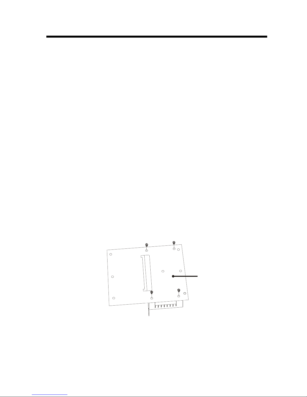
lControloutputconnectionboard installation
Picture14, Control output connection board installation
a)Put in thecontrol output connectionboard aspicture14 shows;
b)Tightentheirremovablescrews;
c)Note: control outputconnectionboardis not hot swappable.
lNotesforControloutputconnectionboard
Picture15, Controloutputconnection boardschematicpicture
1.systeminternalvideo(BNC)
Thisismatrixspecial settingmenuoutput BNCjack.It canconnectto monitor orlooptomatrix
output.
2.RS232 Port
It isastandardserial port forcomputer todownload/uploadsystemdata.
3.RJ45 Port (LAN)
Thisis astandard Ethernet port that connectstohub or switch.
4.RJ45 Port (RS-485)
It is aRS-485 interface for matrix expansion.
4
1
2
3
4

DR-8000 VideoSwitchingMatrix
-17-
nVideoinputswitchingboard
lVideoinputswitching board installation
Picture 16, Video inputswitchingboard installation
a)Put inthe Video input switching board aspicture 16shows;
b)Tightentheirremovablescrews;
c)Note:Videoinputswitching board is hot swappable.
lNotesforVideoinputswitchingboard
Picture17, Video input switching boardschematicpicture
This boardis forswitchingcameravideo signal. Usercanadjust synsignalfor eachvideochannelvia
systemmenuor management software
5
O N
1 2
5
1
2
3
4
BIT1
BIT2
BIT3
BIT4
BIT5
BIT6
BIT7

DR-8000 VideoSwitchingMatrix
-18-
1.DIP (SW2)
Thisis toset theboardfunction.Pleaseset it accordingtotable9.
Table9 Videoinput switchingboardfunction setting
2.DIP (SW1)
ThisDIPsets theVideoinput switchingboard s I. table10 showsthedetail:
Table10Videoinput switching boardIDsetting
BIT1BIT2BIT3BIT4BIT5BIT6BIT7BIT8
OFFOFFOFFOFFOFFOFFOFFOFF
11-6ONONONONONONON
217-32OFFONONONONON
333-48ONOFFONONONON
449-64OFFOFFONONONON
565-80ONONOFFONONON
681-96OFFONOFFONONON
797-112ONOFFOFFONONON
8113-128OFFOFFOFFONONON
9129-144ONONONOFFONON
10145-160OFFONONOFFONON
11161-176ONOFFONOFFONON
12177-192OFFOFFONOFFONON
13193-208ONONOFFOFFONON
14209-224OFFONOFFOFFONON
15225-240ONOFFOFFOFFONON
16241-256OFFOFFOFFOFFONON
17257-272ONONONONOFFON
18273-288OFFONONONOFFON
19289-304ONOFFONONOFFON
20305-320OFFOFFONONOFFON
21321-336ONONOFFONOFFON
22337-352OFFONOFFONOFFON
23353-368ONOFFOFFONOFFON
24369-384OFFOFFOFFONOFFON
25385-400ONONONOFFOFFON
26401-416OFFONONOFFOFFON
27417-432ONOFFONOFFOFFON
28433-448OFFOFFONOFFOFFON
29449-464ONONOFFOFFOFFON
30465-480OFFONOFFOFFOFFON
31481-496ONOFFOFFOFFOFFON
32497-512OFFOFFOFFOFFOFFON
33513-528ONONONONONOFF
34529-544OFFONONONONOFF
35545-560ONOFFONONONOFF
36561-576OFFOFFONONONOFF
37577-592ONONOFFONONOFF
38593-608OFFONOFFONONOFF
39609-624ONOFFOFFONONOFF
BIT5BIT6BIT7BIT8
ON: master OFF: slaver
There should be only one
masterboard in asystem
reserved
DIP SW1)
BoardID Bit
inputchanel BIT1BIT2BIT3BIT4
Table of contents


