BOS Suspension Factory Series User manual
BOS MX SHOCK
Factory/Factory-R
BOS Suspension
4 Impasse Léonce Couture
ZA du Mont Blanc
31200 Toulouse - FRANCE
All serial numbers
Service manual
Manuel de service
SM-43115-001-EN

2
Table of contents
DEAR CUSTOMER................................................................................................................................................. 3
SAFETY INSTRUCTIONS ........................................................................................................................................ 4
GENERAL WARNINGS ...................................................................................................................................... 4
MANUAL .......................................................................................................................................................... 4
USE IN SAFETY ................................................................................................................................................. 4
OPERATING RULES ON YOUR SHOCK .............................................................................................................. 5
ENVIRONNEMENT ........................................................................................................................................... 5
NUMERO DE SERIE........................................................................................................................................... 5
WARRANTY .......................................................................................................................................................... 6
CLEANLINESS ....................................................................................................................................................... 7
TOOLS .................................................................................................................................................................. 8
EXPLODED VIEW .................................................................................................................................................. 9
CLEANING .......................................................................................................................................................... 10
DISASSEMBLY..................................................................................................................................................... 10
PREREQUISITE................................................................................................................................................ 10
HEAD SET/FOOT SET DISASSEMBLY............................................................................................................... 11
DISASSEMBLY OF CYLINDER SET.................................................................................................................... 13
ROD SET DISASSEMBLY.................................................................................................................................. 16
ROD GUIDE SEALS CHANGE ........................................................................................................................... 18
ROD SET REASSEMBLY................................................................................................................................... 20
REASSEMBLY OF CYLINDER SET ..................................................................................................................... 22
REASSEMBLY OF ROD CYLINDER SET............................................................................................................ 24
SPRING REASSEMBLY..................................................................................................................................... 26
SETTINGS TABLE ................................................................................................................................................ 28
NOTES ................................................................................................................................................................ 29
SUMMARY

3
Congratulations, you have just acquired one of our suspensions and we thank you for it.
We have a common passion, motorcycling!
This passion has led us to design our products with all the care and expertise that you, as a user can expect.
Our suspensions are the result of advanced research from our research department, bench validations and
many test sessions with our professional riders.
The goal of all this work is to provide you the best of our technologies for your greatest satisfaction.
In order to make the most of your new acquisition, we invite you to read this user manual carefully. The
mounting instructions and tips for use contained on it will allow you to make the most of the potential of your
suspensions.
Thank you for choosing BOS suspension!
This document was written at the time of the creation of this product, however, BOS Suspension does not
exclude the existence of possible discrepancies due to the evolution of the product since its initial version.
BOS Suspension reserves the right to update the information in this document during the life of the product.
BOS Suspension accepts no liability for any printing problems or errors. All information in this document is
provided without any obligation on the part of BOS Suspension.
©BOS Suspension, Toulouse France
All rights reserved
Any reproduction, even partial, is forbidden without the written permission of the author.
BOS Suspension
4 Impasse Léonce Couture
ZA du Mont Blanc
31200 Toulouse - FRANCE
Valid for all BOS Factory and Factory-R shock absorbers.
DEAR CUSTOMER
4
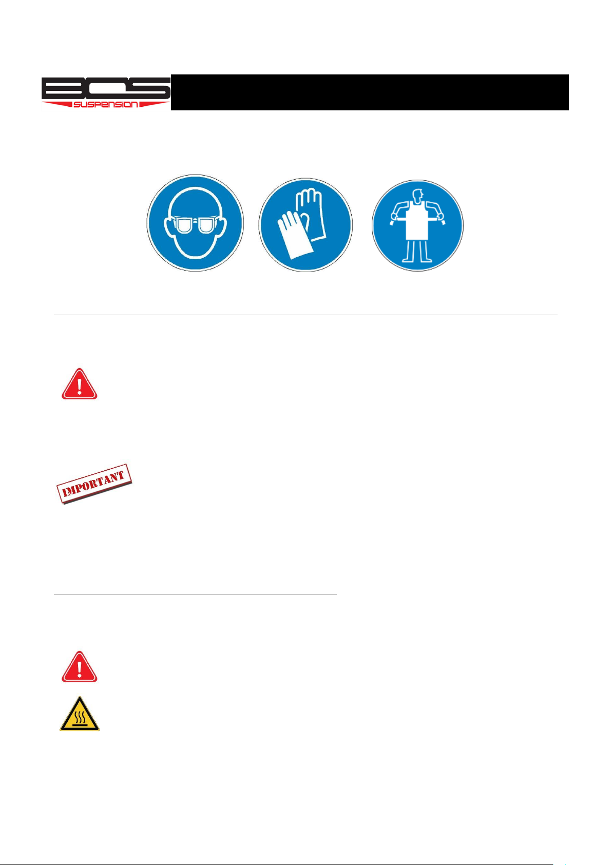
When working on a BOS suspension, please wear appropriate safety equipment such as an apron, safety gloves
and goggles.
When handling the suspension oil, please wear goggles and nitrile gloves.
MANUAL SYMBOLS
USE IN SAFETY
-When using BOS products, make sure you are in good physical shape and not under the
influence of products that affect your lucidity and decision-making capacity (alcohol, drugs,
etc.). If you are not able to ride, do not endanger yourself or any other person.
-The shock absorber has the effect of absorbing shocks, which can generate strong heat. Do not
touch the shock absorber after use. Allow it to cool before attempting any work on it.
SAFETY INSTRUCTIONS
CAUTION operations may impair your safety
or cause damage to your suspension.
Be sure to take note of these warnings.
These indications are provided to
enable you to perform the
operations described in this manual
and to optimize the performance of
your suspension.
GENERAL WARNINGS
The shock absorber is an important element
which has a direct influence on the behaviour of
your vehicle.
This manual must be consulted before using the
BOS shock absorber and during its entire service
life. It is an integral part of the shock absorber.
If necessary, or for any service operation, please
contact an authorized BOS Suspension centre or
consult this manual.
After installation, test your vehicle at low speed
to make sure that it works properly.

5
OPERATING RULES ON YOUR SHOCK
Before carrying out any operation, check that you have the necessary tools to perform it. Some tools will be
specific to BOS shock absorbers, they will be indicated in this manual when using them and can be ordered
directly on our website www.bos-suspension.com.
The disassembly of your shock absorber implies the replacement of certain parts which cannot be reassembled
worn without risk of malfunction of your product (O-rings, seals, wiper seals, rings...).
Before reassembly, clean the parts thoroughly of any impurities and check their state of wear. If this seems
correct, you can reassemble your shock absorber, otherwise, change the worn parts.
ENVIRONNEMENT
Motocross is a wonderful sport that brings you a lot of happiness. However, it is po-
tentially a source of environmental conflict with other people.
Responsible behaviour when using your motocross bike automatically defuses prob-
lems and conflicts. Make sure that you comply with the legislation in force in your
country regarding the disposal of used shock absorber oils and components.
To ensure the continued existence of MX, make sure that you stay within the legal
framework, are environmentally friendly and recognise the rights of others.
NUMERO DE SERIE
The part number of your shock absorber is engraved on the cap (1) of your
shock. It is a sequence of 15 characters including the letter E in the
seventh position. (0000-E-0000000).
1

6
BOS SUSPENSION grants a contractual guarantee under the following conditions:
BOS guarantees its products against all defects in form and manufacturing faults for a period of one year from
the date of original purchase. Proof of purchase will be required for any application of the guarantee. The
warranty is granted to the original owner and is non-transferable. Wearing parts such as wiper seals, O-rings,
guide rings, pins, bushings, screws and bolts are not covered by the warranty.
Application
The application of the warranty is subject to the laws in force in the country or state in which the original
owner resides. If the local legislation differs from the warranty as described here, the warranty is deemed to
be amendable to comply with it.
Limitation
BOS SUSPENSION is not liable for direct, indirect, special, incidental or unforeseen damage resulting from the
use of its products, subject to compliance with local legislation.
Exclusion
The guarantee does not apply in the following cases :
Failure to comply with the installation instructions as described in the installation and adjustment
manual.
Failure to follow the disassembly/assembly instructions as described in the service manual.
Modifications made to the product by the owner or a third party.
Inappropriate use.
Damage resulting from an accident, violent shock, fall, under any circumstances.
Failure to comply with the instructions and maintenance intervals.
Replacement of original parts with parts from manufacturers other than BOS SUSPENSION.
Alteration of the serial numbers with the obvious aim of making it illegible.
Procedure
Regardless of where the product was purchased, the owner must contact an authorised BOS centre to apply
for the guarantee. It is compulsory to produce the purchase invoice. Otherwise, the warranty will not apply.
Sending the product is subject to the prior agreement of the BOS SUSPENSION after-sales service department.
Outward carriage, dismantling and packaging costs are the responsibility of the customer. In the event of
refusal to apply the guarantee, the packaging and return shipping costs are the responsibility of the customer.
WARRANTY

7
When servicing your BOS suspension, make sure that you are working in conditions that will not affect
performance:
Work in a dust-free environment
Work at a clean and organised workstation
Use soft aluminium jaws to protect the equipment when using a vice.
Do not scratch any surfaces when using tools.
Clean the components when disassembling them
Remove the sub-assemblies in the order of disassembly so that you can easily find out how to
reassemble them together.
Long sleeves are recommended or shaved arms.
If you carry out maintenance on your BOS suspension outside a workshop, you should at least :
Avoid dust and air circulation around your work area
A clean tarpaulin to be placed under the suspension on the floor
A repair bracket to maintain the suspension
An oil pan
All the necessary tools listed below
CLEANLINESS
8
-Half shell D18 (ref : 99006)
-Dividing piston tool (ref: 000019-O-031/000019-O-037)
-Rod guide cover tool (ref: 42312-O-012)
-32mm fork tip (ref: 390115-O-024A)
-Corkscrew (ref: 150707-O-030)
-Rod guide ring extractor (ref: 000020-SEO-001/91707-O-013)
Service kit :
-KREVL-46X18-FTY (Lite service Factory)
-KREVL-46X18-FTYR (Lite service Factory-R)
-KREVC-46X18-FTY (Complete service Factory)
-KREVC-46X18-FTYR (Complete service Factory-R)
Cleaning and safety :
Standard tools :
Specific tools :
Oil/Grease/Glues :
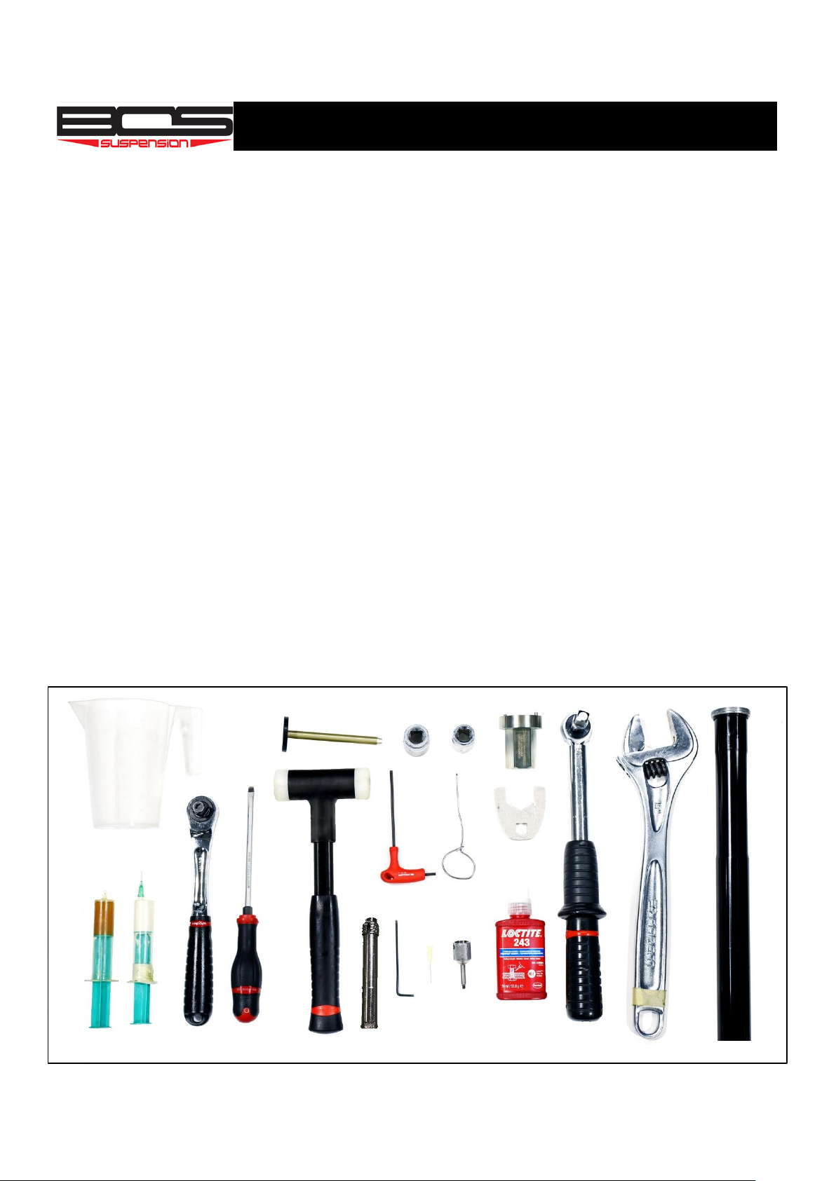
TOOLS
- Safety goggles
- Clean cloths (lint-free)
- Soap (+ hot water)
- Nitrile gloves
- High pressure cleaner
- Apron
- Oil pan
- Oil fountain (optional)
- Torque spanner
- Socket 32/24/19
- Mallet
- Wide flat screwdriver
- Thermal stripper
-AMX1 (0.5L)
-White grease
-Copper grease
- Ratchet key
- Allen key 3 and 5mm
- Spanner
- Pouring spout
- Valve
- Hooking tool
- Soft bite vice
- Needle
-Loctite 243
Degreaser

9
EXPLODED VIEW
10
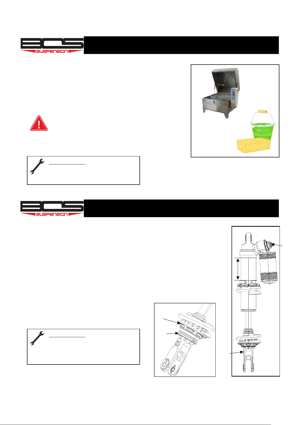
Clean your shock absorber with a washing machine if you have one
available.
Otherwise, use the high pressure cleaner and finish cleaning with hot
water and soap.
Absolutely prohibited : any aggressive product such as
degreaser on joints and spherical bearing. If you use a high-
pressure washer, never direct the jet directly onto the
joints. Regularly remove any soil that may accumulate in the rubber
stop.
PREREQUISITE
1) Before any dismantling, make sure to note down your compression
(1)/rebound(2) and preload(3) settings on a notebook.
To do this, count the number of clicks until the position is completely closed.
Once the setting has been noted, unscrew your settings completely for
operations on your shock absorber.
2) Once the pre-load value has been noted, unscrew the clamp against nut and
then the pre-load nut until the spring is free.
3) Remove the retaining ring (5) from the cup (4)
and remove it and the spring.
CLEANING
Required tools :
- Washing machine
- Soap
DISASSEMBLY
1
2
3
4
5
Required tools :
- Réglet
- Tournevis plat
- Clé ergot

11
HEAD SET/FOOT SET DISASSEMBLY
Unscrew the grub screw from the rod guide cap using a 3mm Allen
key.
Remove it and place it on your workbench
Be carefull not to scratch the rod of your shock during this
operation.
Place the tool on the rod guide cap of your shock and then unlock it
only !
-Be carefull not to scratch the rod of your shock during this
operation.
-Do not unscrew your cap, your shock is still under pressure.
Unscrew the gas cap screw
Remove it and the seal
Required tools :
- 3mm allen key
Required tools :
- Open-end spanner 32 / adjustable spanner
- Rod guide cap tool (ref : 42312-O-012)
Required tools :
- 3mm allen key
12
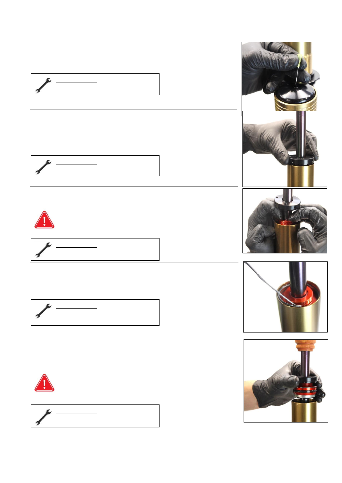
Deflate the shock absorber by inserting a needle into the hole in the
inflation cap.
Let the air flow until you no longer hear any noise.
Unscrew completely the rod guide cap
Press on the rod guide in order to release the retaining ring
Make sure your settings are fully open and leave your needle in the
gas cap port for your comfort.
Remove the retaining ring of the rod guide
Pull gently on the rod until the rod guide is completely free of the cylinder.
Beware of oil splashes, please wear protective glasses.
Required tools :
- Needle
Required tools :
- By hand
Required tools :
- By hand
Required tools :
- Flat screwdriver/hooking tool
Required tools :
- By hand

13
Remove the rod assembly from the cylinder and place it on your
workbench.
-Beware of oil splashes, please wear protective glasses.
-During this step, oil may leak out of your shock absorber. Be sure
to put an oil pan under your vise to collect the used oil.
Pour the contents of your shock into an oil pan and
let it drain for a fex moments.
Don't throw your oils into nature, recycle them
to protect our environment.
DISASSEMBLY OF CYLINDER SET
Tap the gas cap with a mallet to make the locking ring accessible.
Required tools :
- By hand
Required tools :
- By hand
Required tools :
- Mallet
14
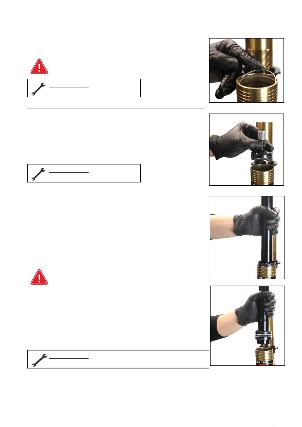
Remove the canister ring by pushing it with a flat screwdriver or
hooking tool. Position it at an angle to facilitate its disassembly.
Be careful not to scratch the inside of the canister during this
operation.
Screw the corkscrew on the inflation cap and pull it vertically to
extract the cap from the canister.
Remove the canister seal with a hook and loop tool and replace with
a new one.
Screw the separating piston extractor tool into the separating piston
and pull vertically until the piston is extracted from the canister
Make sure your shock absorber is properly locked in the vise to
avoid damaging it.
Requiered tools :
- Flat screwdriver / Hooking tool
Requiered tools :
- Corkscrew (150707-O-030)
Requiered tools :
- - Separating piston extractor tool (000019-O-031 and 000019-O-037)

15
Remove the old O-ring with a hook tool and replace with a new one
Be careful not to damage the anti-extrusion rings and piston guide
strips. Check that the o-ring is not rolled up.
Unscrew the compression block using a ratchet and a 24mm socket
Remove the compression block seals (the one on the block and the one
in the head) and replace them with new ones
Then clean the inside of the cylinder and canister properly with a clean cloth or a washing machine if
you have one available.
Clean the compression block, splitter piston and inflation cap properly with a clean cloth as well.
Place all the elements on your workbench before proceeding to the disassembly of the rod assembly.
Required tools :
- Hooking tool
Required tools :
- Ratchet / 24mm socket (Factory) / 32 socket (Factory-R)
Required tools :
- - Hooking tool
16
ROD SET DISASSEMBLY
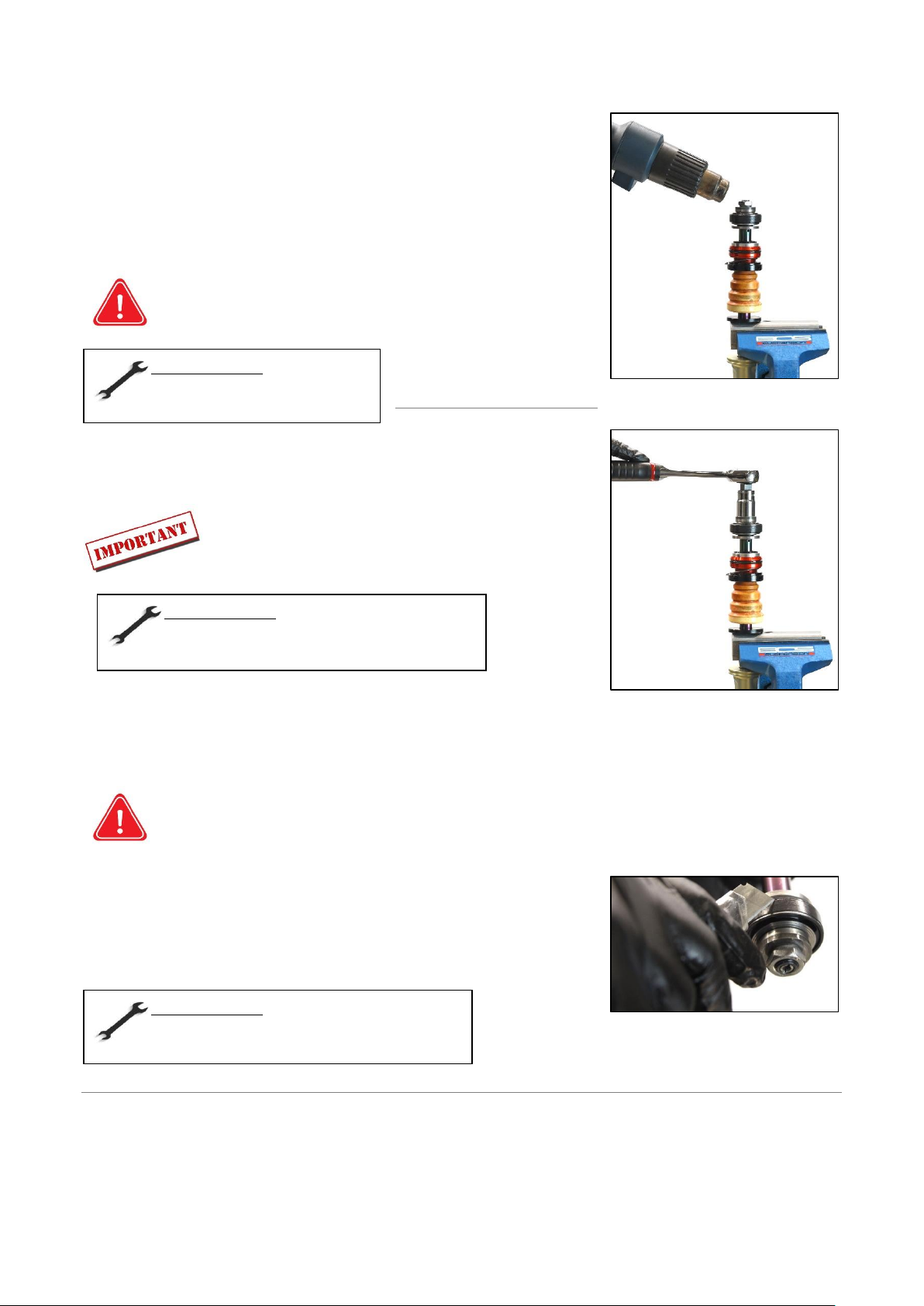
Hold the rod assembly in a vice using a D18mm half-shell (tighten
sufficiently so that the rod does not turn on itself when unscrewing
the nut)
Heat the nut for a few moments
It is recommended to clamp the rod flush with the damper
foot. This will prevent damage to the rod in the effective
working area if the vice is not tight enough.
After heating the nut, loosen it with a ratchet and a 19 mm socket
If you have a Factory-R shock absorber, heat the stop
piston holder at the base and unscrew it with a 19 mm
open-end wrench
Position a valve or screwdriver at the end of the rod and slide the piston assembly over it
Clean the valve assembly and the piston. Use a clean cloth and some degreaser. Dry the parts well
afterwards.
-When cleaning, place all the parts in the order of disassembly on a clean cloth on your
workbench to ensure proper reassembly.
-A wrong order of assembly of the valves will induce a bad functioning of your damper.
Cut the guide band of the main piston with a blade. Remove it
and the O-ring under it.
Position the seal and the new guide band on your piston
Required tools :
- - Thermal scraper
- D18 Half-shell (99006)
Required tools :
- - Ratchet with 19mm socket (Factory)
-19mm flat wrench (Factory-R)
Required tools :
- - Valve
- Blade
17
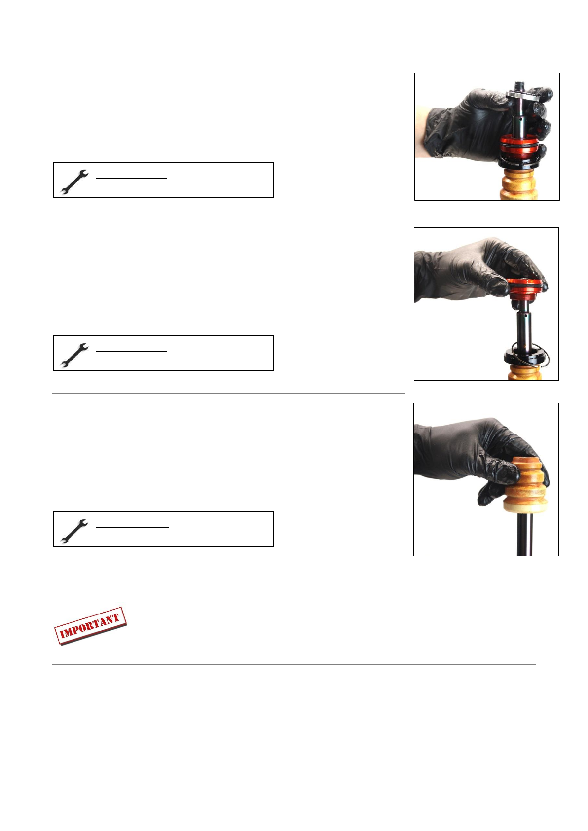
Then remove the rubber rebound stop
Remove the rod guide, the ring and the cap
Finish by removing the bump rubber
Clean all the components you have removed with a clean cloth.
Required tools :
- By hand
Required tools :
- By hand
Required toold :
- By hand

18
ROD GUIDE SEALS CHANGE
Remove the seals from your rod guide using a hook and loop tool
Then remove the used guide ring(s) using tool 000020-SEO-001 and 91707-O-013
Position the sleeve on the guide ring and then screw the screw in so that the grooves are pressed into
the ring
Then tap the top of the tool to remove the ring
Replace the seals with white grease and press-fit the rings (refer to the sectional views below)
Required tools :
- Extractor tool with screw (ref : 000020-SEO-001)
- Extractor socket D18 (ref : 91707-O-013)
- Mallet

19
FACTORY Model
FACTORY-R Model
20
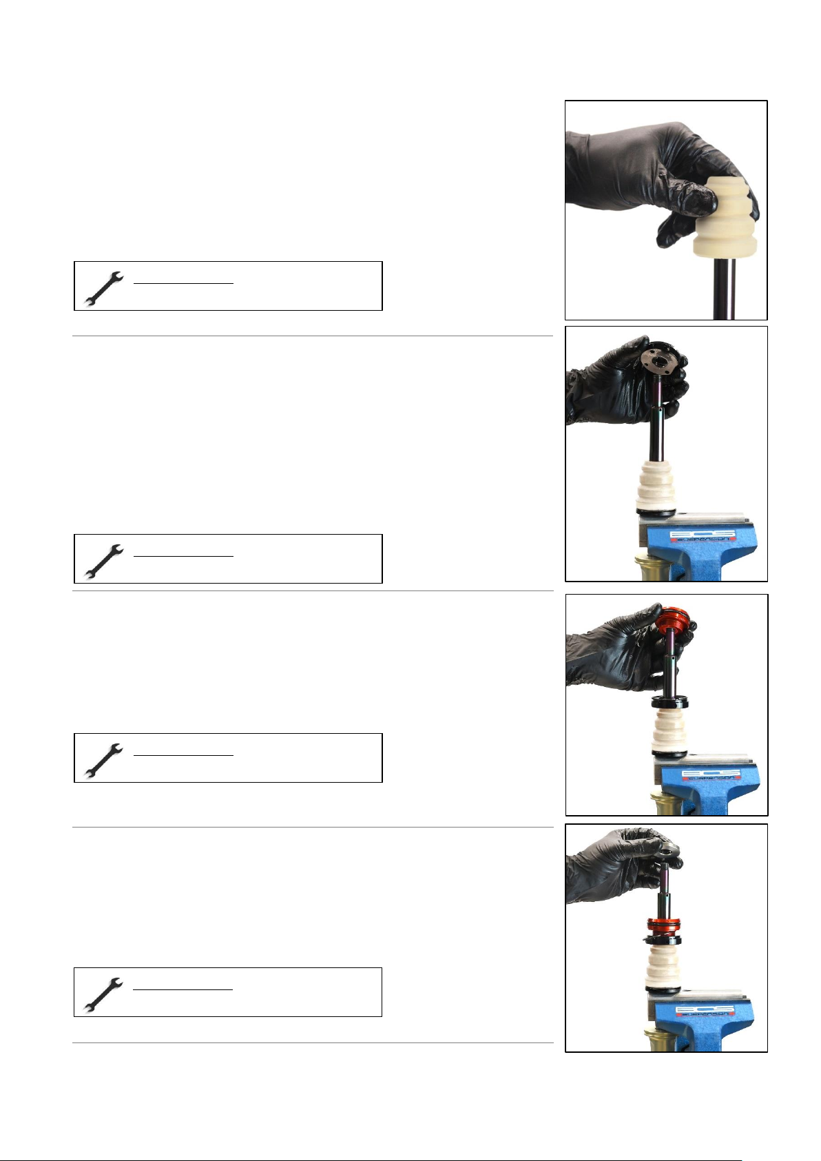
ROD SET REASSEMBLY
Insert the new bump rubber
Insert the rod guide cap and the ring
Insert the reconditioned and greased rod guide
Insert the rebound stop
Required tools :
- By hand
Required tools :
- By hand
Required tools :
- By hand
Required tools :
- By hand
This manual suits for next models
1
Table of contents


