Brave BRPRC110HEB User manual

BRPRC110HE, REV B 1 REV 3/20
OWNER’S MANUAL FOR:
57” Rough Cut Mower
w/ Elec. Clutch Blade Engagement
This machine is intended for use behind a tractor, ATV or UTV
to cut field, brush and saplings up to 2” thick.
Any Questions, Comments, Problems or Parts Orders
Call BRAVE Product Support 1-800-350-8739
WARNING
READ and UNDERSTAND this manual completely before using rough cut mower.
All operators of this equipment must read and completely understand all safety information, operating instructions,
maintenance and storage instructions. Failure to properly operate and maintain the mower could result in serious injury or
death to the operator and bystanders from moving parts that can cut, amputate, flying objects, burns, fire or explosion or
carbon monoxide poisoning and be aware of the following hazards.
•WARNING: Keep all guards and shields in place to avoid injury.
•DANGER: Do not operate the rough cut mower near people. Debris can be thrown hundreds of feet. Clear work area of
foreign objects and debris. Debris thrown by rough cut mower can cause serious injury or death.
•CAUTION: Avoid fires. Keep the machine clean of debris, trash and any other flammable material.
•WARNING: Tighten all nuts and bolts before starting. Replace or repair any safety device, bolts, etc if damaged or worn.
•DANGER: Stay clear of rotating blades. Keep hands and feet away.
•DANGER: Never operate rough cut mower without it mounted securely to the tow vehicle.
•WARNING: Wear protective clothing. Wear close-fitting clothing and other protective devices appropriate for the job.
•DANGER: Keep riders off machine. Riders can be seriously injured or killed by entanglement or by falling.
•DANGER: Exercise caution while working near machine. Failure to heed warnings may lead to serious injury or death.
•DANGER: Always maintain a safety distance. Never operate rough cut mower with bystander’s present. The rough cut
mower creates a serious discharge hazard. Never point the discharge direction at anyone. Be aware of where bystanders
are located, especially children. Never assume they will remain where you last saw them. Be sure to know what is in the
path of the discharge area.
STOP!
ADD OIL TO ENGINE BEFORE USING: Engine is shipped without oil. DO NOT start rough cut mower without first adding oil.
INSPECT COMPONENTS: Closely inspect to make sure no components are missing or damaged.
ITEM NUMBERS: BRPRC110HEB
MANUAL SERIAL TAG HERE

BRPRC110HE, REV B 2 REV 3/20
SAFETY INTRODUCTION
Your safety, and the safety of others, is very important. To help you make informed
decisions about safety, we have provided operating procedures and other information on
labels and in this manual. This information alerts you to potential hazards that could hurt
you or others.
This safety alert symbol is used to indicate safety instructions. Follow these
instructions to avoid personal injury and/or property damage. Read and follow all
instructions in this manual and the included engine manual.
You will find important safety information in a variety of forms, including:
Safety Labels – on the mower.
Safety Messages – preceded by a safety alert symbol and one of three signal
words: DANGER, WARNING, or CAUTION.
These signal words mean:
DANGER:Indicates an imminently hazardous situation that, if not avoided, will result in
death or serious injury. This signal word is to be limited to the most extreme situations
typically for machine components which, for functional purposes, cannot be guarded.
WARNING: Indicates a potentially hazardous situation that, if not avoided, could result in
death or serious injury, and includes hazards that are exposed when guards are removed.
It may also be used to alert against unsafe practices.
CAUTION:Indicates a potentially hazardous situation that, if not avoided, may result in
minor or moderate injury. It may also be used to alert against unsafe practices.
This entire manual is filled with important safety information. Please read it
carefully.

BRPRC110HE, REV B 3 REV 3/20
IMPORTANT SAFETY INFORMATION
WARNING: Do not allow anyone to operate this equipment who has not fully read and
comprehended the safety manual and who has not been properly trained in the safe
operation of the equipment.
WARNING: Operator should be familiar with all functions of the unit.
DANGER:Keep hands, feet, hair and clothing away from moving parts.
WARNING: Remove all objects from the work area that might be picked up and thrown by
the blades.
WARNING: Do not mow when children and others are around.
WARNING: Keep all safety shields and deflectors in place during operation.
WARNING: Shut off the engine and allow the mower blades to come to a complete stop
before making any adjustments to the mower.
WARNING: Shut off engine before disconnecting the mower from the tow vehicle or
attempting to move the mower by hand.
WARNING: Never carry children or passengers.
WARNING: Do not allow children to operate this machine.
WARNING: Follow all safety precautions outlined by the manufacturer of the tow vehicle
being used to pull this product.
This entire manual is filled with important safety information. Please read it
carefully.

BRPRC110HE, REV B 4 REV 3/20
Clean or Replace Any Safety Signs That Are Not Readable or Damaged
Replacement decals can be purchased from your local dealer or
Call BRAVE Product Support 1-800-350-8739

BRPRC110HE, REV B 5 REV 3/20
ASSEMBLY INSTRUCTIONS
Read the complete assembly instructions before starting the assembly.
You should have:
- one mower deck assembly
- two carrier arm assemblies
- two rear tire assemblies
- one ATV tongue assembly
A. ASSEMBLY OF MOWER WHEELS
1. Set the mower deck assembly on wood blocks so that it is suspended off the ground.
Note: The operator controls are on the front of the deck. (Left and right are determined by
looking in the direction of travel or by standing at the rear of the deck assembly looking
forward.)
2. Install the rear tire assemblies on the carrier arm assemblies. Remove the hex nut and lock
washer from the rear tire assembly and install the 5/8”x7-1/2” tire axle bolt through the hole in
the carrier arm assembly. See figure 1. Secure assembly with the lock washer and hex nut
provided on the rear tire assembly. The rear tires should be offset to the outside of the deck
assembly on both sides. See figure 2.
3. Install the two carrier arm assemblies in the pivot arms, which are located on the mower deck
assembly. Place the assembly so that the castered tires are on the front and the fixed tires are
on the back. See figure 2. Secure with 1/2" x 3-1/2" hex head bolts and lock nuts provided on
the pivot arms. Mount the height adjust screw on the deck assembly in the hole provided.
Secure with the 1/2”x1” hex head bolt and lock nut provided on the height adjust screw.
Note: Tighten 1/2” x 3-1/2” and 1/2” x 1” hex head bolts until just snug. This area needs to
pivot when adjusting the height. Under tightening can result in excessive wear and
flexing. Over tightening will make adjusting the cutting height very difficult.
B. INSTALLATION OF TONGUE ASSEMBLY
1. The tongue can be installed either on the left or right caster assembly depending on how the
tow-behind mower will be towed. See figure 2. Secure the hitch pivot on the chosen caster
assembly with the 1/2” x 3-1/2” hex head bolt, lock washer, and nut provided.
2. Install the tongue into the hitch pivot and secure by placing the provided 5/16” wire lock pins on
each side of the hitch pivot.
Note: To help prevent any unwanted pin removal caused by oncoming debris install the 5/16”
wire lock pins with the wire lock section back from the direction of travel. See Figure 3.

BRPRC110HE, REV B 6 REV 3/20
Figure 1: Rear Tire Assembly Installation
Figure 2: Assembly of Carrier Arm Assy., Hitch Pivot, and Tongue
Rear Tire Assy.
(Attach on outside for
both left and right sides)
Pivot Arm
Height Adjust
Screw
Hitch Pivot – Attach to
Either Left or Right
Carrier Arm Assy.
Tongue
Front (Rubber
Flap Side)
Carrier Arm
Assy.
Direct Behind Position
Offset Position
Flat Washer
Rear Tire
Carrier Arm
Assembly
Hex Nut and
Lock Washer
Cup Washer
Bolt
Spanner
Tube

BRPRC110HE, REV B 7 REV 3/20
Figure 3: ATV Tongue Assembly
OPERATIONS AND ADJUSTMENTS
This safety alert symbol is used to indicate safety instructions. Follow
these instructions to avoid personal injury and/or property damage.
Read and follow all instructions in this manual and the attached engine
manual.
WARNING: Do not allow anyone to operate this equipment who has not fully read and
comprehended the safety manual and who has not been properly trained in the safe
operation of the equipment.
WARNING: Operator should be familiar with all functions of the unit.
A. TONGUE CONFIGURATIONS AND ADJUSTMENTS
WARNING: Shut off the engine and allow the mower blades to come to a complete stop
before adjusting the tongue.
The hitching system is designed so that the rough cut mower can be pulled directly behind a tow
vehicle or offset to the left or right. See Figure 4.
Note: When pulling the mower directly behind, the hitch pivot should be fastened on the right
carrier arm for maximum maneuverability. See Figure 2. When pulling the mower in
the offset position the hitch pivot can be fastened on either the right or left carrier arm.
See Figure 2.
Wire Lock Section of
Wire Lock Pin
(Placed Back From
Direction of Travel)
5/16” Wire
Lock Pins
Direction of Travel
Screw Pin Shackle
Clevis
Tongue
Shift Tongue Left or Right
Between Holes
BRPRC110HE, REV B 8 REV 3/20
The tongue is equipped with a screw pin shackle clevis to provide movement in all directions on
rough uneven ground. To prevent loss of the screw pin due to vibration or debris, place the screw
pin through the tow vehicle hitch and clevis and turn the screw pin until snug.
The tongue is designed to adjust from left to right within the hitch pivot. This allows the mowers
position to be varied behind the tow vehicle. This is accomplished by pulling the 5/16” wire lock
pins out and choosing two other hole locations on the tongue. See Figure 3.
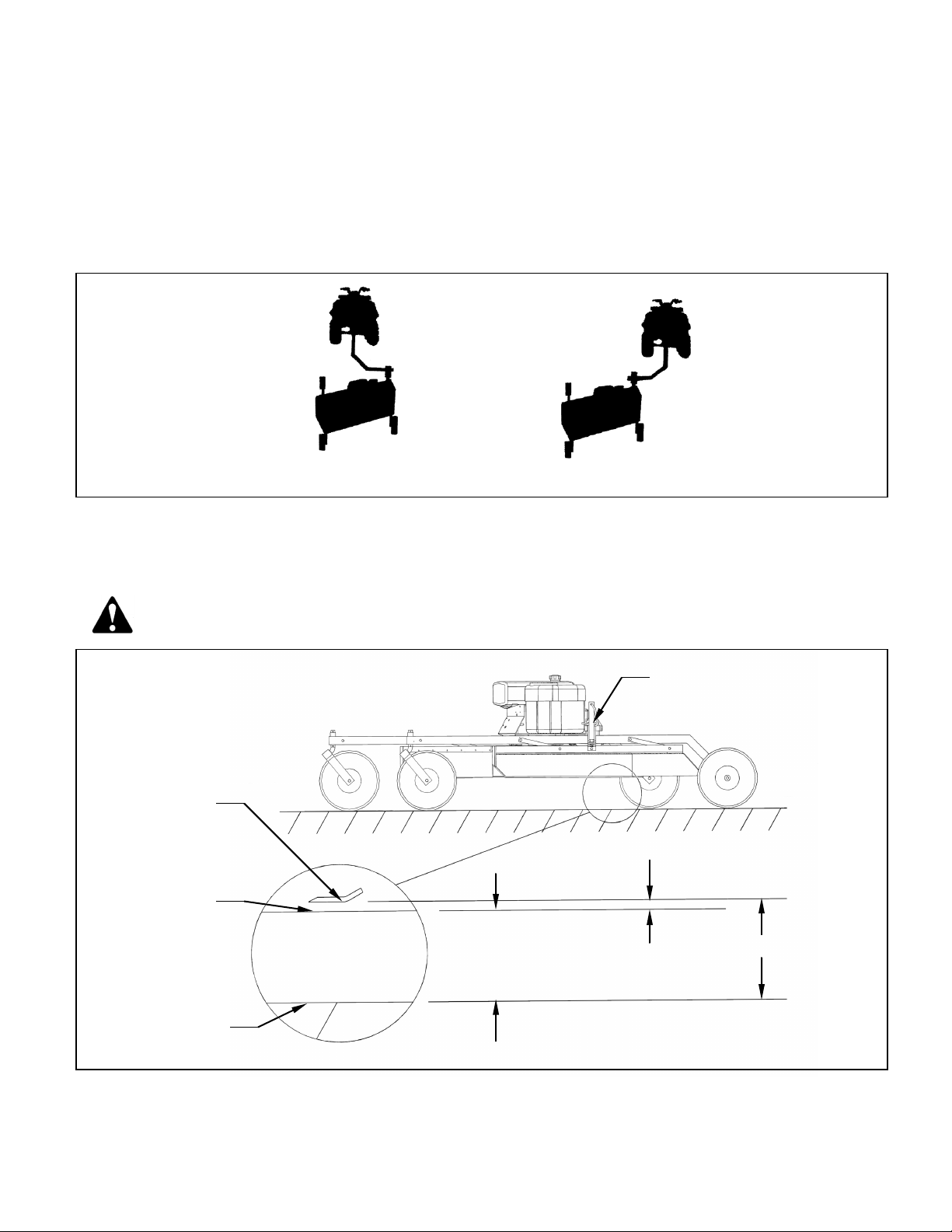
Figure 4: Rough Cut Tow Behind Towing Suggestions
B. ADJUSTING CUTTING HEIGHT
WARNING: Shut off the engine and allow the mower blades to come to a complete stop
before adjusting the cutting height.
Figure 5: Adjusting Rough Cut Mower Cutting Height
Offset
Directly Behind
Measure This Distance
and Add 1-5/16” to get
Cutting
Height
Cutting Height
1-5/16”
Smooth Surface
Lower Edge of
Deck
Mower Blade
Adjustment Crank: Roughly 6
turns equals 1.0”

BRPRC110HE, REV B 9 REV 3/20
The cutting height can be adjusted in a range from 2.0" to 8.0". This is accomplished by turning
the height adjust cranks on both sides of the mower. See Figure 5. Turn the cranks clockwise to
raise the mower cutting height and counter-clockwise to lower the mower cutting height.
DANGER: Shut off tow vehicle engine and allow mower blades to stop completely before
attempting to measure the cutting height.
Adjust the mower as follows:
1. Pull the mower on to a smooth, level surface.
2. Adjust the mower evenly from side to side by measuring to the ground from the lower edge of
the mower deck. The desired height will be the distance from the ground to the outside lower
edge of the mower deck plus 1-5/16”. The mower blade cutting edge is 1-5/16” above the
outside lower edge of the mower deck.
Note: If the height adjust cranks do not turn easily, the pivot bolts holding the carrier arm
assemblies and height adjust screw may be too tight. Loosen the pivot bolts slightly to
allow easier pivoting. Care should be taken not to loosen too much or excess wear and
flexing may occur. Greasing the threads may also allow greater ease in adjustment.
Note: After leveling mower deck, quick field adjustment can be completed by counting crank
turns. Roughly 6 turns will equal 1” of vertical movement.
The adjustment crank may unturn due to vibration. This will allow the mower’s cutting height to
change. The crank can be secured by folding it down between the adjustment nut tube and the
upper pivot support. See Figure 6.
Figure 6: Securing Crank While Not In Use
Adjustment Crank
Carrier Arm
Adjustment Nut Tube
Upper Pivot Support

BRPRC110HE, REV B 10 REV 3/20
C. STARTING ENGINE
WARNING: Set parking brake on tow vehicle.
Attach mower tongue to tow vehicle.
WARNING: Do not start rough cut mower unless it is attached to the tow vehicle.
Turn on the fuel shut off valve (red colored rotating knob) located inline on the fuel hose. The off
position on the valve is when the red handle lines up with the “O” symbol.
Set the choke to the desired position.
Set the throttle at approximately half throttle.
Start engine and allow engine to warm up.
Set the engine speed at about half throttle and engage the mower blades clutch by pulling
outward on the PTO switch. (The PTO switch is located at the front of the mower deck on the
control panel.)
Note: To help extend the life of the clutch the engine rpm should be placed as low as possible
before clutch engagement. If the engine should stall during clutch engagement raise
the engine rpm until clutch engagement is possible.
CAUTION: If the mower’s engine dies while in use, remove the rough cut mower from the
uncut area before attempting to engage the clutch. Inspect the blades for any obstructions
that may prevent blade engagement. Failure to follow these instructions may result in
premature clutch and belt failure or a fire.
Adjust engine speed to full throttle.
D. SHUTTING OFF ROUGH CUT MOWER
WARNING: Shift to neutral and set the parking brake before dismounting the tow vehicle.
Slow the engine speed down and disengage the clutch by pushing inward on the PTO switch.
Allow engine to cool down for a short time before moving the ignition switch to the off position.
Turn off the fuel shut off valve (red colored rotating knob) located inline on the fuel hose. The off
position on the valve is when the red handle lines up with the “O” symbol.

BRPRC110HE, REV B 11 REV 3/20
E. MOWER OPERATION
DANGER:Keep hands, feet, hair and clothing away from moving parts.
CAUTION:Clean or replace any safety signs that are not readable or damaged.
WARNING: Remove all objects from the work area that might be picked up and thrown by
the blades.
WARNING: Do not mow when children and others are around.
WARNING: Do not fill fuel tank while engine is running or hot.
WARNING: Keep all safety shields and deflectors in place during operation.
CAUTION:Remove grass build up from under safety shields before each use. Do not
remove safety shields while engine is running. Dry grass build up around belts and
sheaves can cause fires.
WARNING: Shut off engine before disconnecting the mower from the tow vehicle or
attempting to move the wing mower by hand.
WARNING: Never carry children or passengers.
WARNING: Do not allow children to operate this machine.
CAUTION: Slow down and watch the ends of the mower when making turns so objects
are not struck and/or run over.
WARNING: Look down, to the sides, and behind before and while backing to avoid
backing over something or someone. Care should also be taken while backing so that the
wing mower or mowers do not jackknife and damage hitches.
WARNING: Stop the mower blades on the mower if the tow vehicle becomes stuck or
stops going forward because of loss of traction. Shut off the engine on the mower before
attempting to push or pull the tow vehicle.
Listen to the rough cut mower engine while mowing. The engine should run free and not work too
hard. Working the engine too hard will cause overheating and premature failure.
CAUTION: If the mower’s engine dies while in use, remove the rough cut mower from the
uncut area before attempting to engage the clutch. Inspect the blades for any obstructions
that may prevent blade engagement. Failure to follow these instructions may result in
premature belt failure or a fire.

BRPRC110HE, REV B 12 REV 3/20
Do not allow material to build up on the air inlet to the engine cooling system. Special care should
be taken to make sure the engine is getting enough inlet air. Do not allow the engine cooling fins
under the shroud to be blocked. If air flow over the engine is restricted, the engine could
overheat.
F. DRIVE BELT REMOVAL AND TENSION – Refer to Figure 7
WARNING: Shut off engine and allow mower blades to stop turning before making any
adjustments or repairs.
Remove the safety shields.
Loosen the nuts on the spring-loaded idler; adjust bolt until the belt can be slipped off the idler and
drive sheaves.
Slip the belt down under the drive sheave and off the blade spindle sheaves.
Install the new belt and then adjust the tension as follows: See Figure 7.
Figure 7: Belt Pattern and Spring Adjustment
Engine/Clutch
Front
Initial Spring Length (New Belt):
2-1/2” to 2-9/16”
Running Spring Length:
2-3/4” to 3-1/4”
Only Include
Spring in
Measurement

BRPRC110HE, REV B 13 REV 3/20
Adjust the nuts on the spring-loaded idler adjuster bolt until the length of the spring is between 2-
1/2” and 2-9/16”. This is the initial belt break in spring length. When the belt is broken in after
several hours of mowing, the running spring length should be between 2-3/4” and 3-1/4”. For
maximum belt life, periodic checks every 3-4 hours should be done to make sure the spring length
has not exceeded the recommended running length.
Note: Failure to periodically adjust the belt tension will result in severe belt wear and
premature belt failure.
G. MOWER BLADE REMOVAL, BALANCING & INSTALLATION
CAUTION: Sharp blades can cause bodily injury if not handled properly.
When removing the blade, it is recommended that a block of wood be placed between the blade
and the underside of the mower deck. This will allow the removal of the blade without the need to
hold the blade by hand.
CAUTION: Always balance the mower blades each time they are sharpened.
Out of balance mower blades cause excess vibrations which lead to premature bearing failures,
bolts coming loose, and overall deterioration of the wing mowers.
CAUTION: Always properly tighten the blade bolts to the specified torque. Failure to do so
can lead to unwanted loosening of the blade and damage to the blade holding saddle.
The Models BRPRC110HE use Part # (202141) blade bolt. This particular hex head bolt is a 3/4”
– 16NF x 1-1/4” long, grade 5 and it’s proper torque is 300 ft-lbs.
To ease in the blade installation process, use the same block of wood and method used during
the removal of the blades.
H. LUBRICATION
There are three lubrication points on the rough cut mower -- one spring-loaded idler pivot and
two caster wheel pivots. Lubricate at approximately 10 hr. intervals or more often as required in
dusty conditions.
I. FUSE LOCATION
These particular mowers come equipped with a 10 AMP mini blade type fuse. The fuse is located
behind the ignition switch/control panel in a black rubber inline fuse holder.
J. STORAGE
Turn off the fuel shut off valve (red colored rotating knob) located inline on the fuel hose. The off
position on the valve is when the red handle lines up with the “O” symbol. If the mower is stored
outside, the engine should be covered to prevent water from getting inside the engine during
heavy rainstorms. See the Engine Manual for additional information.

BRPRC110HE, REV B 14 REV 3/20
K. EPA EVAPORATIVE COMPONENTS
This mower has been designed and built to meet all current EPA regulations. Any modification to
the fuel tank, fuel lines, vapor hose, fuel cap, roll-over / fuel vapor valve, carbon canister
(California Only) and hose clamps are prohibited. Replacement evaporative components should
be purchased from Brave. Any questions about EPA regulations or evaporative components can
be directed to Brave at 800-350-8739

BRPRC110HE, REV B 15 REV 3/20
BRPRC110HE ROUGH CUT MOWER SPECIFICATIONS
Model
BRPRC110HE
ENGINE
Engine Make
Honda
Engine Model
GXV630RHQYF
Engine Muffler
MUF-0526-KIT
Cylinders
2
Cycles
4
Crankshaft
Vertical
Engine HP
20.8 @ 3600
Bore
78mm 3.07in
Stroke
75mm 2.83in
Displacement
688cm, 41.97 cu-in
Oil Capacity
1.7 Liters, 1.8 quart
Crankshaft Dia.
1 inch
Key Slot
.25 in
Crankshaft Length
3.11 inch
Threaded Hole in End of Crankshaft
7/16-20UNF2B
Engine Mounting Bolts
5/16-18x1.50 Through Bolt
Starter
12 volt
Choke
remote cable
MOWER
Fuel Tank
3 Gallon
Effective Cutting Width
57"
Deck Construction
10 ga. Welded steel
Cutting Height
2" to 8"
Height Adjustment
Single Crank
Rear Wheels (Fixed) (4 ply Turf Pneumatic)
Two 15/600 x 6
Front Wheels (Caster) (4 ply Turf Pneumatic)
Two 5.30/4.50 x 6
Blade Dia.
2-30"
Engine Speed, Blades Running
3600 RPM
CLUTCH
Type
Electric Clutch
DIMENSIONS
Length
108"
Width
60"
Height
29"
Weight
580 lbs.
HITCH
Hitch Type
ATV Tongue

BRPRC110HE, REV B 16 REV 3/20
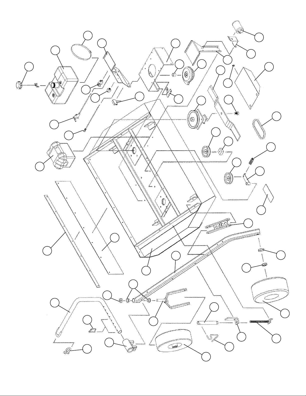
BRPRC110HE ROUGH CUT MOWER PARTS LIST
Ref #
Part #
Description
Qty
1
202141
Blade Bolt, .75"-16UNF x 1.25" 2
2
214030
Cup Washer 6
3
216002
Wire Lock Pin, .31" x 2.50" 2
4
216009
Screw Pin Shackle Clevis 1
5
222012
Single Split Collar (1" I.D. x .1/2" Thick) 2
6
222005
Worm Drive Hose Clamp (9-1/4" to 10-1/8" Clamping Dia.) 2
7
225005
Compression Spring, 4.50"L x 1-3/32" O.D. x .125" Wire dia. 1
8
226014
Offset Wheel Assy. (15/600 x 6, Urethane Foam-Flatproof) 2
9
226015
Centered Wheel Assy. (5.30/4.50 x 6, Urethane Foam-Flatproof) 2
10
238004
"V" Belt, .62" x 95.9" O.C. 1
11
241001
Flat Idler, 4" O.D. x 3/8" Hole 1
12
241009
Flat Idler (Steel), 4" O.D. x 1/2" Hole 1
13
243010
Plastic Bearing, 1-3/8" O.D. x 1.00" I.D. 4
14
243015
Precision Sealed Wheel Bearings (2" O.D. x 1" I.D.) 8
15
258022
Spindle Assembly 2
Sub
Assy
900075 Spindle Shaft (1)
Sub
Assy
900160 Housing Assembly (with two bearings) (1)
Sub
Assy
243006 Bearing (6206 w/trash guard seals) (2)
Sub
Assy
600271 Bearing Spacers (3.33" Long) (1)
Sub
Assy
241008 Sheave, (7-1/2" Dia., B-Section) (1)
16
258018
Electric Clutch
1
17
259002
Offset Mower Blade, 2-1/2" Wide, 30" Long, 3/4" Hole
2
18
264003
Hour/Tack Meter
Optional
19
264005
PTO Switch
1
20
3104E463B
Ignition Switch
1
21
269000
Choke Control, 20"
1
22
269009
Throttle Control, 27"
1
23
275001
Control Panel Decal, Starting Instructions
1
23
275002
Warning Decal General
1
23
275003
Danger Decal, Cut Finger
4
23
275007
Warning Decal, Belt Shield
2
23
ZUBRPRC110HE
Branding Decal & Safety Sheet Set
1
24
277002
Rubber Gromet
6

BRPRC110HE, REV B 17 REV 3/20
25
277035
Gas Cap - Audible Click/Tethered, Non-Venting 1
26
277036
Carbon Canister - 300cc 1
27
277045
Fuel Tank, 3 Gal., EPA/CARB Certified 1
28
600126
Flap Retainer Strip 1
29
600133
Belt Shield 2
30
600142
Upper Pivot Support 2
31
600143
Safety Belting 1
32
600146
Crank Arm 2
33
600172
Engine Support Bracket 1
34
600189
Idler Spacer Block 1
35
600198
Clutch Stop 1
36
600200
Spacer, 1.38" O.D. x 1.33" Wall x 1.00" Long 1
37
600290
Canister Support 1
38
600317
Control Panel 1
39
600318
Tank Support 1
40
900049
Battery Box Assy. 1
41
900058
Hitch Pivot 1
42
900061
Pivot Arm 4
43
900062
Height Adjust Nut 2
44
900066
Screw Adjuster 2
45
900069
Mower Deck 1
46
900082
Tongue 1
47
900106
Carrier Arm 2
48
900128
Idler Arm Assy. 1
*
243000
Bronze Bearing, 1/2"I.D. x 3/4" O.D. x 1.50" Long 1
49
900148
Caster Fork 2
*
MUF-0526-KIT
Muffler and Manifold (Silver) 1
*
HON1420
Drainzit Oil Drain Aid 1
*
GXV630
Honda Vertical V-Twin Engine 1
*Not Shown in exploded view
BRPRC110HE, REV B 18 REV 3/20
12
3
4
6
7
5
8
1
2
11
16
17
20
19
18
21
44
26
25
27
28
24
35
23
31
30
33
40
14
42
47
10
32
45
13
49
46
15
38
9
22
29
34
37
41
43
48
36
39
BRPRC110HE, REV B 19 REV 3/20

BRPRC110HE, REV B 20 REV 3/20
Table of contents
Other Brave Lawn Mower manuals


