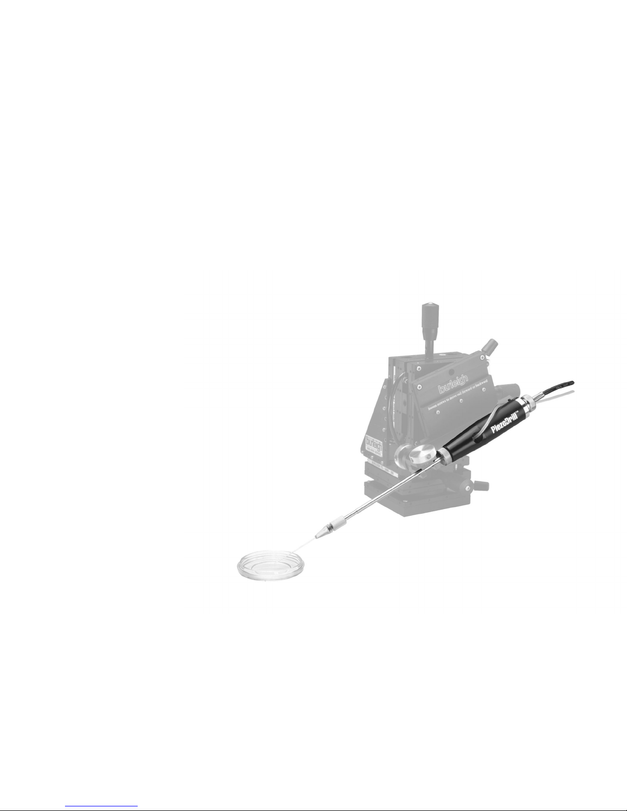
Burleigh PiezoDrill User manual

User’s Manual
PiezoDrill
Inertial Impact Drill
08572-M-01 (Rev. D)
Copyright ãBurleigh Instruments, Inc. 2002
All Rights Reserved
PIEZODRILLis a trademark of Burleigh Instruments, Inc.


Table of Contents
Table of Contents ........................................................................................................................... 1-3
1. Introduction – Mercury Warning ............................................................................................ 1-1
2. Equipment and Materials ........................................................................................................ 2-1
Injection Pipettes........................................................................................................................ 2-2
Purchasing Injection Pipettes........................................................................................... 2-2
Manufacturing Injection Pipettes...................................................................................... 2-2
Fluids Used in the Injection Pipette.................................................................................. 2-4
Holding Pipettes......................................................................................................................... 2-5
Manufacture or Purchase of Holding Pipettes ................................................................. 2-5
Pipette Holders .......................................................................................................................... 2-6
Hollow Tube Pipette Holders............................................................................................ 2-6
Solid Pipette Holders........................................................................................................ 2-7
Microinjector............................................................................................................................... 2-8
The Importance of a Good Microinjector.......................................................................... 2-8
Micromanipulators...................................................................................................................... 2-9
3. Setup ......................................................................................................................................... 3-1
Filling the Injection Pipette with Fluorinert ................................................................................. 3-1
Using Mercury in the Pipette...................................................................................................... 3-2
Attaching the PiezoDrill to the Microscope and the Micromanipulator ...................................... 3-3
Critical Success Factors ............................................................................................................ 3-4
PiezoDrill Settings and Control Parameters .............................................................................. 3-4
PiezoDrill Settings When Fluorinert is Used in the Pipette .............................................. 3-4
PiezoDrill Settings When Mercury is Used in the Pipette ................................................ 3-4
Using the PiezoDrill to Break Off the Sperm Tail............................................................. 3-6
Foot Pedal Control of Two Independently Adjustable Channels ..................................... 3-6
4. Recommended Procedure for a Successful Injection with Fluorinert in the Pipette........ 4-1
5. Recommended Procedure for a Successful Injection with Mercury in the Pipette .......... 5-1
6. Troubleshooting Guide ........................................................................................................... 6-1


Burleigh PiezoDrill
Inertial Impact Drill User’s Manual 1 Introduction
Burleigh Instruments, Inc. 2002 (08572-M-01 Rev D) 1-1
The information contained in this document is privileged information and
is intended for the personal and confidential use of Burleigh PiezoDrill customers.
1. Introduction – Mercury Warning
This PiezoDrill User’s Manual is a supplement to the PiezoDrill Operating
Manual. The purpose of the User’s Manual is to describe recommended
peripheral equipment and procedures that will ensure the successful
operation of an overall microinjection system incorporating the PiezoDrill.
For detailed information about operating the PiezoDrill itself, please refer to
the PiezoDrill Operating Manual. Please note:
§We have documented one formula for successful system application of
the PiezoDrill. Undoubtedly, there are other combinations of pipette
shapes, pipette fluids, etc. that can be used successfully. This is a “work
in progress.” We know there is more to learn, and everyone reading this
can contribute to our combined, increased understanding. If you have
comments and suggestions, please send them to info@burleigh.com.
§We can help only with the process of making productive, non-destructive
penetrations of oocytes. Burleigh Instruments cannot guarantee
successful ICSI or nuclear transfer procedures because that depends on
the quality of the oocytes and many other factors that are beyond our
control.
WARNING MERCURY WARNING
USERS WHO CHOOSE TO USE MERCURY IN THE INJECTION PIPETTE
WITH THE PIEZODRILL ARE STRONGLY CAUTIONED THAT THE
EXPOSURE TO, USE OR HANDLING OF MERCURY POSES SIGNIFICANT
HEALTH RISKS, INCLUDING WITHOUT LIMITATION NEUROLOGICAL
DAMAGE, KIDNEY DAMAGE, BRAIN DAMAGE, MEMORY LOSS,
BLINDNESS AND COGNITIVE IMPAIRMENT. USERS WHO CHOOSE TO USE
MERCURY IN THE INJECTION PIPETTE WITH THE PIEZODRILL ARE
STRONGLY ADVISED TO FULLY FAMILIARIZE THEMSELVES WITH THE
HAZARDS ASSOCIATED WITH MERCURY, AS WELL AS GUIDELINES FOR
USE AND HANDLING. MERCURY SHOULD NOT BE USED IN THE
INJECTION PIPETTE WITH THE PIEZODRILL BY ANY INDIVIDUALS OR
LABORATORIES UNWILLING TO BEAR THE ENTIRE RISK OF EXPOSURE
TO MERCURY, OR UNABLE TO PROPERLY SAFEGUARD AGAINST
MERCURY EXPOSURE. BURLEIGH INSTRUMENTS, INC., ITS AFFILIATES,
EMPLOYEES, SUCCESSORS AND ASSIGNS HEREBY DISCLAIM IN ITS
ENTIRETY AND SHALL HAVE NO LIABILITY WHATSOEVER TO ANY
PARTY, INCLUDING WITHOUT LIMITATION ITS CUSTOMERS, THEIR
RESPECTIVE EMPLOYEES OR OTHER USERS OF THE PIEZODRILL, FOR
DAMAGES OR LOSSES ARISING OUT OF OR OTHERWISE RELATED TO
THE USE OR HANDLING OF, OR THE EXPOSURE TO, MERCURY.
BURLEIGH INSTRUMENTS, INC. DOES NOT RECOMMEND OR SUGGEST
THE USE OF MERCURY IN CONNECTION WITH THE PIEZODRILL AND THE
USER ASSUMES ALL RISKS ASSOCIATED WITH ANY DECISION TO DO
SO: BURLEIGH INSTRUMENTS, INC. DISCLAIMS ALL REPRESENTATIONS
AND WARRANTIES REGARDING THE USE OF MERCURY IN CONNECTION
WITH THE PIEZODRILL.


Burleigh PiezoDrill
Inertial Impact Drill User’s Manual 2 Equipment and Materials
Burleigh Instruments, Inc. 2002 (08572-M-01 Rev D) 2-1
The information contained in this document is privileged information and
is intended for the personal and confidential use of Burleigh PiezoDrill customers.
2. Equipment and Materials
Figure 1 is a typical configuration of a microinjection system incorporating
the PiezoDrill and the following types of equipment:
Equipment type Equipment examples
1. Inverted microscope Leica DMIRB/E, Nikon TE200/300,
Olympus IX70, Zeiss Axiovert 135
2. Injection pipette Humagen or self-manufactured
3. Holding pipette Humagen or self-manufactured
4. Pipette holder Eppendorf Cell Tram (Oil), Narishige
H-7 and HI-7
5. Microinjector Eppendorf Cell Tram (Oil)
6. Micromanipulator Burleigh MIS-5400, Eppendorf
TransferMan NK, Leitz (or Leica)
Manipulator, Narishige MMO-22D
7. PiezoDrill Burleigh PiezoDrill
Figure 1: Typical microinjection set up incorporating the PiezoDrill

Burleigh PiezoDrill
Inertial Impact Drill User’s Manual 3 Setup
2-2 (08572-M-01 Rev D)
Burleigh Instruments, Inc. 2002
The information contained in this document is privileged information and
is intended for the personal and confidential use of Burleigh PiezoDrill customers.
The equipment examples are listed in alphabetical order. The list of
examples is not exhaustive; the absence of a particular brand or model from
the list is not necessarily an indication that this model will not work with the
PiezoDrill. The models listed do represent a popular set of choices. We
have direct evidence that all of these models work well with the PiezoDrill.
Injection Pipettes
Purchasing Injection Pipettes
Use of a correctly manufactured pipette is a critical success factor for
productive PiezoDrill utilization. If the pipette is not shaped correctly, the
procedure will not be successful. PiezoDrill pipettes manufactured to
Burleigh specifications can be purchased from:
Humagen Fertility Diagnostics, Inc.
2400 Hunter’s Way
Charlottesville, VA 22911
Toll-free in the US: 800-937-3210
International: (804) 979-4000
Fax: (804) 295-5912
Email: humag[email protected]t
Web: www.humagenivf.com
See Appendix A for a Humagen price list for PiezoDrill pipettes.
NOTE We have included one Humagen injection pipette with the PiezoDrill
for your initial use.
Manufacturing Injection Pipettes
It is suggested that you begin your work with purchased pipettes from
Humagen. After you show success you can begin to make your own.
Pipettes used with the PiezoDrill are much simpler to manufacture than
pipettes used in conventional procedures. However, use of a correctly
manufactured pipette is a critical success factor for productive PiezoDrill
utilization.

Burleigh PiezoDrill
Inertial Impact Drill User’s Manual 2 Equipment and Materials
Burleigh Instruments, Inc. 2002 (08572-M-01 Rev D) 2-3
The information contained in this document is privileged information and
is intended for the personal and confidential use of Burleigh PiezoDrill customers.
The PiezoDrill eliminates the need for beveling and drawing a sharp tip on
the pipette. These features were required for conventional zona penetration,
but the PiezoDrill allows penetration with a flat pipette. Therefore, the
optimal pipette is simply broken or cut flat at the precise internal and external
diameter required for the application. This operation can be done easily
using a standard microforge with a 100 or 150 µm platinum filament and
good resolution optics at high magnification (300X-500X). Any rough edges
remaining after the pipette is broken should be gently removed by heat
polishing using low heat. The tip of the pipette does not need to be acid
etched.
The tip of the pipette should be bent to form a section that can be placed
parallel to the working surface. The optimal angle of the bend depends on
the placement of the micromanipulator. In general, the angle will be 15-30o.
A bent tool with a section of the pipette that is parallel to the working surface
facilitates visualization of material in the pipette tip in the same focal plane
as the specimen.
The length of the “dogleg” created in the bent pipette is an important
consideration in obtaining optimum performance. Excellent results have
been achieved with the following pipette dimensions (shown in Figure 2):
Glass 1.0 mm OD, 0.75 mm ID, no filament (Sutter
Instruments, Novato, CA)
Total taper length 16 mm
Dogleg length 6 – 7 mm
Dogleg angle 15 - 30°

Burleigh PiezoDrill
Inertial Impact Drill User’s Manual 3 Setup
2-4 (08572-M-01 Rev D)
Burleigh Instruments, Inc. 2002
The information contained in this document is privileged information and
is intended for the personal and confidential use of Burleigh PiezoDrill customers.
Figure 2: Injection pipette specification
Fluids Used in the Injection Pipette
Fluid is required inside the pipette to facilitate aspiration and transfer of
material. The fluid used should possess non-toxic and water imiscible
properties and should be “non wetting” to the glass surface as well. This
property allows a high degree of control over the rate and precision of the
movement of material.
Most researchers use light paraffin oil in the pipette for traditional
procedures. However, our experience indicates that heavier fluids in the
pipette work better with the PiezoDrill. Some researchers have used
mercury for PiezoDrill procedures. However, due to the significant health
risks associated with exposure to mercury, Burleigh Instruments, Inc. does
not suggest, approve, endorse or recommend the use of mercury with the
PiezoDrill. Please see our mercury warning on page 1-1.
We recommend Fluorinert (FC-77, Fisher Scientific, cat. no. AC-12381-
0500) which has been used for years by many practitioners of embryo
micromanipulation. Fluorinert is heavier than water and mineral oil and
works very well with the PiezoDrill. (Note: The microinjection system uses
oil as the controlling fluid. Fluorinert is used only in the pipette itself.)
Section 3.1 describes the procedure for filling the microinjection pipette with
Fluorinert and connecting it to the oil-based microinjection system.
NOTE We have included one bottle of FC-77 Perfluoro Compound with the
PiezoDrill for your initial use.

Burleigh PiezoDrill
Inertial Impact Drill User’s Manual 2 Equipment and Materials
Burleigh Instruments, Inc. 2002 (08572-M-01 Rev D) 2-5
The information contained in this document is privileged information and
is intended for the personal and confidential use of Burleigh PiezoDrill customers.
Holding Pipettes
Manufacture or Purchase of Holding Pipettes
The Humagen price list in Appendix A includes holding pipettes with 85 µm
and 120 µm outside diameters. The 85 µm OD pipette is made for mouse
oocytes; the 120 µm OD pipette is intended for swine and bovine oocytes. It
is important that the outside diameter of the holding pipette be slightly
smaller than the oocyte. This allows the oocyte to be held into position and
anchored to the slide or dish surface. “Pinning” the oocyte in this manner
prevents the oocyte from moving when PiezoDrill vibrations begin. The
inside diameter of the holding pipette should be large enough that some
cytoplasm is held in place by the holding pipette. We recommend an ID of
20 to 25 µm because:
It provides more perivitelline (PV) space between the zona and the oolemma
at the other side of the oocyte where the PiezoDrill will penetrate the zona.
Since zona vibration settings are higher than the settings for the oolemma,
the pipette must not engage the oolemma while vibrating at the zona settings.
PV space allows the zona to be penetrated with no possibility that the
oolemma will be penetrated accidentally at the same time.
It is easier to break the oolemma at low vibration settings when the
cytoplasm is held in this manner, which improves oocyte viability.
Figure 3 illustrates the correct size and position of the holding pipette. Note:
This pipette has a slightly larger outer diameter than what we recommend.
Because this particular pipette is not bent and approaches the oocyte from
above, it still works effectively to pin the oocyte.
NOTE We have included one Humagen holding pipette with the PiezoDrill for
your initial use.

Burleigh PiezoDrill
Inertial Impact Drill User’s Manual 3 Setup
2-6 (08572-M-01 Rev D)
Burleigh Instruments, Inc. 2002
The information contained in this document is privileged information and
is intended for the personal and confidential use of Burleigh PiezoDrill customers.
Figure 3: Holding the oocyte for optimal zona and oolemma
penetration
Pipette Holders
There are two types of instruments used to hold the pipette and facilitate the
flow of material controlled by a syringe. Both will work with the PiezoDrill,
but they may require slightly different amplitude settings as explained below.
Hollow Tube Pipette Holders
Hollow tube systems (see Figure 4) allow the hydraulic fluid used to control
the movement of material to pass through the rod and enter directly into the
pipette via an O-ring type of holder at the front. The syringe to control
pressure is attached directly to the rear of the mounting rod with a piece of
Teflon or polyethylene tubing. The PiezoDrill is configured to grip the
hollow rod and allow the tubing to pass through the hole in the cone shaped
part of the drill (see the PiezoDrill Operating Manual for assembly
instructions). Hollow tube systems may require slightly higher settings on
the PiezoDrill amplifier because some of the energy transmitted from the
PiezoDrill is lost in the rubber O-ring attachment to the pipette. It is very
important that the pipette is held tightly in this connection.

Burleigh PiezoDrill
Inertial Impact Drill User’s Manual 2 Equipment and Materials
Burleigh Instruments, Inc. 2002 (08572-M-01 Rev D) 2-7
The information contained in this document is privileged information and
is intended for the personal and confidential use of Burleigh PiezoDrill customers.
Figure 4: Hollow pipette holder connected to the PiezoDrill and the
syringe
Solid Pipette Holders
Solid pipette holders (see Figure 5) require tubing from the syringe to be
coupled directly to the pipette using Teflon or polyethylene tubing. With this
system, the hydraulic fluid passes from the syringe tubing directly into the
pipette. The mounting rod contains a groove- and washer-based tip to secure
the pipette to the holder. It is very important that the pipette is held tightly.
Optimum amplitude settings are lower with this system because there is no
O-ring to absorb energy.

Burleigh PiezoDrill
Inertial Impact Drill User’s Manual 3 Setup
2-8 (08572-M-01 Rev D)
Burleigh Instruments, Inc. 2002
The information contained in this document is privileged information and
is intended for the personal and confidential use of Burleigh PiezoDrill customers.
Figure 5: Solid pipette holder connected to the PiezoDrill and the
syringe
Microinjector
The Importance of a Good Microinjector
A good microinjector is critical to successful use of the PiezoDrill. It is
important that the syringe responds precisely to fingertip commands. If
pressure inadvertently increases during the procedure, Fluorinert will be
pushed out of the end of the pipette. If pressure inadvertently decreases,
Fluorinert will move back into the pipette and the PiezoDrill will not operate
as efficiently. Because of its viscosity, oil is easier to control than Fluorinert.
Therefore, a marginal microinjector may suffice for traditional procedures
but may be inadequate for use with the PiezoDrill.
The Eppendorf Cell-Tram is by far the most precise and consistent device
that we have used, although satisfactory results have been achieved with
careful control of other microinjectors as well.

Burleigh PiezoDrill
Inertial Impact Drill User’s Manual 2 Equipment and Materials
Burleigh Instruments, Inc. 2002 (08572-M-01 Rev D) 2-9
The information contained in this document is privileged information and
is intended for the personal and confidential use of Burleigh PiezoDrill customers.
Micromanipulators
The PiezoDrill should work with any micromanipulator. However, our
experience to date suggests that the stiffer and sturdier the manipulator, the
easier the process will be. Because the Narishige manipulator is so small and
light, Burleigh makes a special adapter which replaces the Narishige B-8 ball
joint (see the PiezoDrill Operating Manual for assembly instructions). The
Narishige Adapter provides a stiffer connection that improves PiezoDrill
performance. We also make a Leitz Adapter to replace the ball joint on the
Leitz manipulator (see the PiezoDrill Operating Manual for assembly
instructions).
The Burleigh MIS-5400 is a stiff, sturdy micromanipulator that has been
optimized for peak PiezoDrill performance. We highly recommend it for use
with the PiezoDrill. On many occasions, our customers have seen much
improved PiezoDrill performance using the MIS-5400 over other types of
micromanipulators. The MIS-5400 is stiffer and holds the PiezoDrill more
securely. This allows for more efficient transfer of vibrations from the
PiezoDrill to the pipette tip.


Burleigh PiezoDrill
Inertial Impact Drill User’s Manual 3 Setup
Burleigh Instruments, Inc. 2002 (08572-M-01 Rev D) 3-1
The information contained in this document is privileged information and
is intended for the personal and confidential use of Burleigh PiezoDrill customers.
3. Setup
Filling the Injection Pipette with Fluorinert
A very effective way of filling a pipette with Fluorinert is to use a 5 or 10 ml
syringe fitted with a blunted 20 gauge needle. Blunting the needle (breaking
off the end) produces a better flow of material.
1. Cover the needle with a piece of polyethylene tubing1so that about 1
centimeter of tubing extends over the end of the needle. Remove all air
bubbles from the syringe and tubing then carefully fit the butt end of the
pipette into the overhanging tubing.
2. Firmly depress the syringe plunger, allowing the Fluorinert to displace
the air in the pipette, thus filling the pipette. Depending on the size of
the opening at the tip, which can be very small for most applications, this
procedure may take a minute or so.
3. Disconnect the pipette from the tubing, use positive pressure in the
microinjector to push the oil in that system to the end of the tubing,
attach it to the pipette holder of choice. It is important that there are
minimal air bubbles trapped between the oil and the Fluorinert when the
pipette is coupled to the pipette holder in order to achieve good control
during the micromanipulation procedures outlined in Section 4.
Figure 6 illustrates the proper technique for filling the injection pipette with
Fluorinert.
1 Suggested tubing: Tygon
Microbore, 0.38 mm ID, 2.29 mm OD, 0.76 mm wall, Cole-
Parmer cat. no. EW-06418-03

Burleigh PiezoDrill
Inertial Impact Drill User’s Manual 3 Setup
3-2 (08572-M-01 Rev D)
Burleigh Instruments, Inc. 2002
The information contained in this document is privileged information and
is intended for the personal and confidential use of Burleigh PiezoDrill customers.
Figure 6: Filling the injection pipette with Fluorinert
Using Mercury in the Pipette
We are aware that some customers are using mercury in the injection pipette
with the Piezodrill, especially for work on mouse oocytes. Burleigh
Instruments Inc. does not suggest, approve, endorse or recommend the use of
mercury in the PiezoDrill. Mercury should not be used with the PiezoDrill
by any individuals or laboratories unwilling to bear the entire risk of
exposure to mercury or unable to properly safeguard against mercury
exposure.
NOTE Please see our mercury warning on page 1-1.
We synthesized the following information from customers using mercury in
the pipette:
Mercury is available from Fisher Scientific, M-140, "Mercury Metal Re-
distilled". One-quarter pound is about 10 ml volume and lasts a long time.
To dispense the mercury, use a syringe with a blunt nose needle. The gauge
will be different depending on the pipettes, but a 30-g needle with metal hub
commonly is used. Draw the mercury up into the syringe tip. Inject mercury

Burleigh PiezoDrill
Inertial Impact Drill User’s Manual 3 Setup
Burleigh Instruments, Inc. 2002 (08572-M-01 Rev D) 3-3
The information contained in this document is privileged information and
is intended for the personal and confidential use of Burleigh PiezoDrill customers.
through the back-end of the pulled pipette, leaving about ¼ inch long strip
inside the pipette. Mount the pipette onto the injector. Push mercury down
to the tip. There maybe a small air bubble between the oil (or water) and the
mercury. Draw some media through the tip of the pipette so that the media
provides a protective barrier between the mercury and the tip of the pipette.
You are now ready to draw sperm cells into the pipette to begin the ICSI
process.
After a few sperm injections, the cytoplasm from the egg begins to build-up
on and inside the tip of the injection pipette. The pipette becomes sticky and
it becomes impossible to move the sperm heads in and out smoothly.
Therefore, it is necessary to frequently "wash" the pipette tip. It is good
practice to have a drop of medium in the ICSI dish that is used strictly as a
wash drop. Move the pipette into this drop and eject a little bit of mercury
from the tip. Actually, it is washed in and out but every time the pipette is
drawn back up, whatever mercury was ejected will break off and form a
bubble in the media drop. Once outside the pipette, the mercury will not go
back through the fine tip of the pulled pipette, resulting in a medium drop
with many little bubbles of mercury.
For this reason, all of the ICSI dishes must be considered mercury
contaminated. All oil, pipettes and all ICSI dishes must be disposed of as
hazardous waste and labeled as containing mercury. Place used pipettes into
a 50-ml plastic tube for containment and disposal. Even the water or oil in
the tubing that attaches to the microinjection system must be considered
mercury contaminated. Drips on the counter can't be placed into regular
trashcans; they are mercury contaminated and should go into hazardous
waste receptacles.
Keep a vacuum flask near where the mercury is used and stored. If a spill
occurs, use a regular household-type hand vacuum with a plastic tube
attached to the vacuum bottle to clean all potentially contaminated surfaces.
Attaching the PiezoDrill to the Microscope and the Micromanipulator
Place the PiezoDrill control unit so that the controls can be easily reached
while sitting at the microscope. The PiezoDrill is equipped with foot pedal
controls that allow two independent sets of parameters to be readily accessed
via independent foot pedals. This feature is important since different
parameters will be employed when drilling the zona pellucida versus
breaking the cytoplasmic membrane (oolemma). Insert the pipette holder
into the PiezoDrill according to the instructions in the Operating Manual,
then clamp the pipette holder onto the manipulator. It is desirable to clamp
the pipette holder as closely as possible to the PiezoDrill (see examples in
Figures 4 and 5). Also, it is important that all connections, including the
Narishige or Leitz adapter, if used, are completely tightened. This type of
attachment will ensure optimum vibrations at the pipette tip.

Burleigh PiezoDrill
Inertial Impact Drill User’s Manual 3 Setup
3-4 (08572-M-01 Rev D)
Burleigh Instruments, Inc. 2002
The information contained in this document is privileged information and
is intended for the personal and confidential use of Burleigh PiezoDrill customers.
Critical Success Factors
The PiezoDrill produces mechanical pulses that travel longitudinally along
the pipette and vibrate the tip. The tip vibrations aid in cutting (drilling)
through the zona pellucida and the oolemma in a less traumatic manner than
conventional procedures. One key to successful system operation is to
ensure that the pulses emanating from the PiezoDrill are accurately
transmitted through all the mechanical linkages in the system to the pipette
tip. If any connection in the system is loose, the frequencies can be altered
and the PiezoDrill may not operate effectively. Therefore, on the injection
pipette side of the microscope, check the following:
§The pipette must be held tightly in the pipette holder.
§The pipette holder must be tightly clamped in the PiezoDrill.
§The pipette holder must be firmly attached to the micromanipulator,
ideally as close to the PiezoDrill as possible.
§The micromanipulator must be securely attached to the microscope on a
sturdy platform/mounting system.
PiezoDrill Settings and Control Parameters
The PiezoDrill Operating Manual contains recommended beginning trial
settings for the amplifier for both zona and oolemma penetration. However,
the optimum settings will vary depending on the type of manipulator, the
type of fluid used in the pipette, the shape of the pipette and the nature of the
oocyte itself. In general, a stiffer manipulator will allow lower settings, as
will a heavier fluid in the pipette.
PiezoDrill Settings When Fluorinert is Used in the Pipette
ADJUSTMENT ZONA SETTING OOLEMMA SETTING
Amplitude 20 20
Duration 75 75
Frequency 10 2
Bandwidth 100 100
PiezoDrill Settings When Mercury is Used in the Pipette
Table of contents