California Trimmer Mower
Maintenance Manual
10
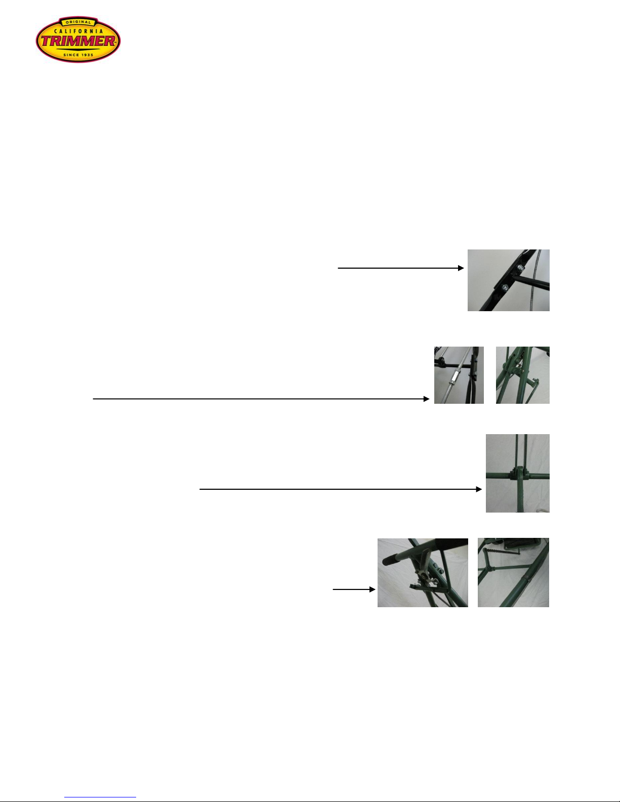
Height Adjustment
All models
Two different ranges of height adjustments are available. The higher range is achieved with the “caster
bracket” (no. 1) in the bottom hole (as shown). The lower range is achieved with the “caster bracket” (no.
1) in the top hole.
With the “caster bracket” (no.1) in the lower hole, the “height adjustment lever” (no. 2) will utilize the top 4
to 5 holes of the “quadrant” (no. 3).
With the “caster bracket” (no. 1) in the top hole, the “height adjustment lever” (no. 2) will utilize the bottom
4 to 5 holes of the “quadrant” (no. 3).
In either height range, moving the “height adjustment lever” (no. 2) towards the front of the mower will
raise the height in small increments. Moving the “height adjustment lever” (no. 2) towards the back of the
mower will lower the height in small increments.
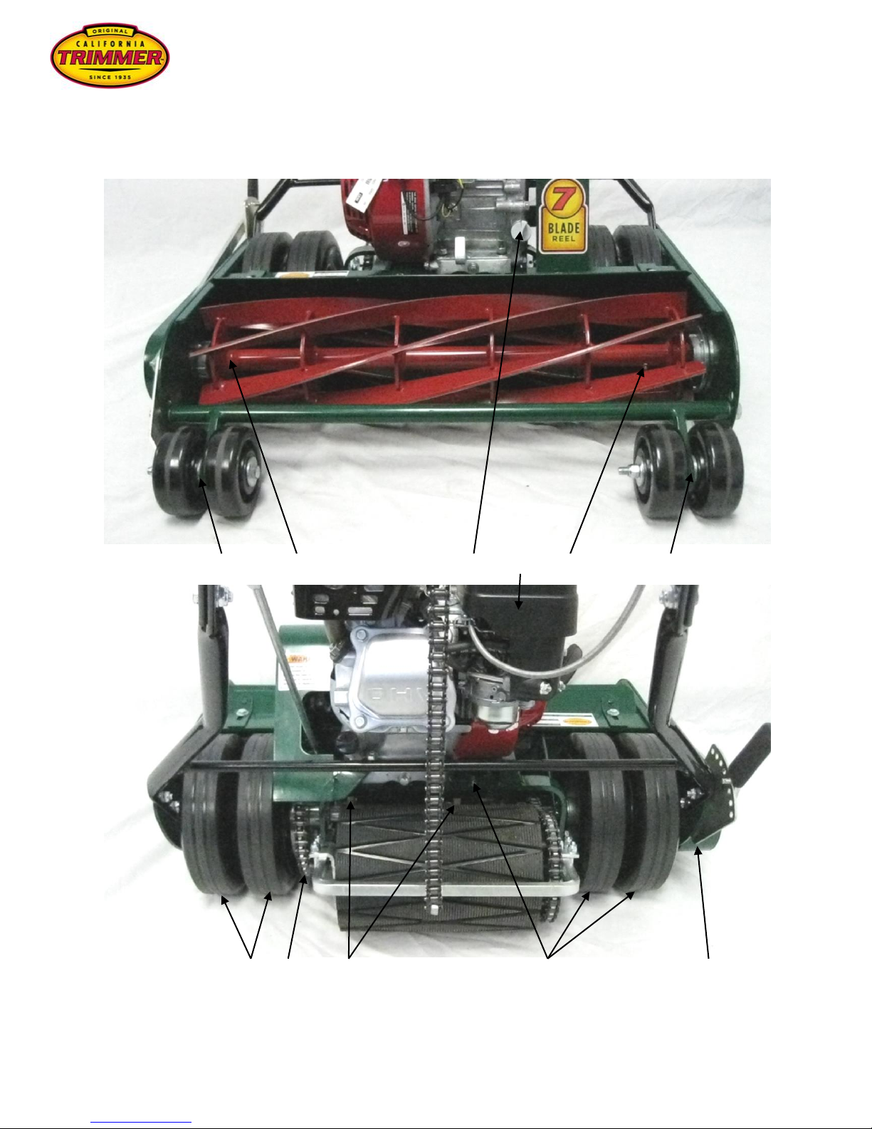
1
3 2 4 5 6
To change the range setting, take the “height adjustment lever” (no. 2) out of the holes of the “quadrant”
(no. 3) and move it in the direction of the change. Back if the “caster bracket” (no.1) is being moved to
the top hole or forward if the “caster bracket” (no.1) is being moved to the bottom hole. Loosen the
“caster wheel nut” (no. 6).
Remove the nut on the “tie rod” (no. 4), slide the “tie rod” (no. 4) out, being careful not to lose the washer
between the “adjuster bracket” (no. 5) and the frame (washer not shown). Slide the “tie rod” (no. 4)
through the desired hole of the side plate, “caster bracket” (no. 1), and the other side plate. Place the
washer (not shown) on the “tie rod” (no. 4) between the frame and “adjuster bracket (no. 5). Install the nut
on the “tie rod” (no. 4). Do not over tighten this nut, the height adjuster pivots at this point. Tighten the
“caster wheel nut” (no. 6).