Only the latest issues of above codes should be used, and are
available from either The National Fire Protection Agency, Bat-
terymarch Park, Quincy, MA 02269 or The Canadian Standards
Association, 178 Rexdale Blvd., Rexdale, Ontario M9W 1R3
Recognize safety information. This is the safety-alert symbol .
When you see this symbol on the furnace and in instructions or
manuals, be alert to the potential for personal injury.
Understand the signal words DANGER, WARNING, and CAU-
TION. These words are used with the safety-alert symbol. DAN-
GER identifies the most serious hazards which will result in severe
personal injury or death. WARNING signifies a hazard which
could result in personal injury or death. CAUTION is used to
identify unsafe practices which would result in minor personal
injury or product and property damage.
INTRODUCTION
The furnace is shipped as a packaged unit, complete with burner
and controls. It requires a line voltage (115 vac) connection to
control box, a thermostat hook-up as shown on wiring diagram, oil
line connection(s), adequate duct work, and connection to a
properly sized vent.
The air handling capacity of this furnace is designed for cooling
airflow. Refer to Table 5 for expected airflows at various external
duct static pressures. LOCATION
This furnace is not water tight and is not designed for outdoor
installation. This furnace shall be installed in such a manner
as to protect electrical components from water. Outdoor
installation would lead to a hazardous electrical condition and
to premature furnace failure.
Do not use this furnace as a construction heater. Use of this
furnace as a construction heater exposes furnace to abnormal
conditions, contaminated combustion air, and lack of air
filters. Failure to follow this warning can lead to premature
furnace failure and/or vent failure which could result in a fire
hazard and/or bodily harm.
This furnace is approved for reduced clearances to combustible
construction, therefore, it may be installed in a closet or similar
enclosure. It may be located in a basement or on the same level as
area to be heated. In any case, unit should always be installed level.
In a basement or when installed on the floor, it is recommended
that unit be installed on a concrete pad that is 1- to 2-in. thick.
On dirt floors, furnace may be installed on concrete blocks. Place
blocks under all 4 corners and under center of furnace. Center
block 22 in. from back of furnace forward.
The required minimum clearances for this furnace are specified in
Table 1.
The furnace should be located as close as possible to chimney or
vent in order to keep vent connections short and direct. The
furnace should also be located as near as possible to center of air
distribution system.
Step 1—Air for Combustion and Ventilation
Installation of this furnace in an area where it will receive
contaminated combustion air must be avoided. Such contami-
nation would include the following: ammonia, chlorine,
hydrogen sulfide, halogenated hydrocarbons, carbon tetra-
chloride, cleaning solvents, hydrochloric acid, water soften-
ing chemicals, and similar chemicals. Failure to follow this
warning will lead to premature rusting of heat exchanger and
possible premature furnace failure and/or vent failure which
could result in fire hazard and/or bodily harm.
This furnace should be installed in a location in which facilities for
ventilation permit satisfactory combustion of oil, proper venting,
and maintenance of ambient temperature at safe limits under
normal conditions of use. The location should not interfere with
proper circulation of air within the confined space. (See NFPA-31,
Section 1.5.)
In addition to air needed for combustion, process air shall be
provided as required for: cooling of equipment or material,
controlling dew point, heating, drying, oxidation or dilution, safety
exhaust, and odor control.
In addition to air needed for combustion, air shall be supplied for
ventilation, including all air required for comfort and proper
working conditions for personnel.
The barometric draft regulator (included with furnace) shall be
installed in same room or enclosure as furnace in such a manner as
to prevent any difference in pressure between regulator and
combustion-air supply.
Air requirements for operation of exhaust fans, kitchen ventilation
systems, clothes dryers, and fireplaces shall be considered in
determining the adequacy of a space to provide combustion-air
requirements.
In unconfined spaces in buildings of conventional frame, brick, or
stone construction, infiltration MAY be adequate to provide air for
combustion, ventilation, and dilution of flue gases. This determi-
nation must be made on an individual installation basis and must
take into consideration the overall volume of unconfined space, the
number of windows and ventilation openings, the number of doors
to the outside, internal doors which can close off unconfined space,
and overall tightness of building construction. Consideration must
also be given to the amount of storage items (furniture, boxes, etc.)
within the unconfined space which take away from the air volume.
Many new buildings and homes (and older ones that have been
weatherized) MUST BE considered as being of tight construction,
therefore, infiltration will not be sufficient to supply necessary air
for combustion and ventilation.
A building can be considered as being of tight construction when:
1. Walls and ceilings exposed to outside atmosphere have a
continuous water vapor retarder with a rating of 1 perm or less
with openings gasketed or sealed, and/or
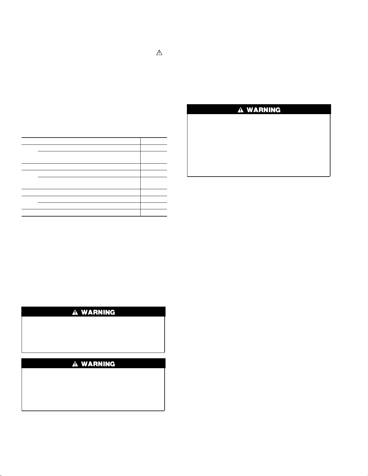
Table 1—Minimum Clearances to Combustible
Materials (In.)
UNIT APPLICATION LOW-BOY
Sides Furnace 0
Supply Plenum and Warm-Air Duct Within 6 ft
of Furnace 1
Back 0
Top Furnace Casing or Plenum 2
Horizontal Warm-Air Duct Within 6 ft of
Furnace 2
Bottom 0*
Flue
Pipe Horizontally or Below Pipe 4
Vertically Above Pipe 8
Front 8
* Floor may be combustible.
NOTE: Adequate service clearance should be provided over and above these
dimensions as required.
2
→
→


