used when installed on combustible materials and wood flooring.
This special base is not required when this furnace is installed on
the manufacturer’s coil assembly, or when the manufacturer’s coil
box is used. See Figure 2 for clearance to combustible material
information.
Improper installation, adjustment, alteration, service, mainte-
nance, or use can cause carbon monoxide poisoning, explo-
sion, fire, electrical shock, or other conditions which may
cause personal injury or property damage. Consult a qualified
installer, service agency, local gas supplier, or your distribu-
tor or branch for information and assistance. The qualified
installer or agency must use only factory-authorized and
listed kits or accessories when modifying this product.
Failure to follow this warning could result in electrical shock,
fire, personal injury or death.
This furnace is designed for minimum continuous return-air
temperature of 60°F db or intermittent operation down to 55°F db.
Return-air temperature must not exceed 85°F db. See Figure 3.
For accessory installation details, refer to the applicable instruction
literature.
NOTE: Remove all shipping brackets and materials before oper-
ating the furnace.
CODES AND STANDARDS
Follow all national and local codes and standards in addition to
these instructions. The installation must comply with regulations
of the serving gas supplier, local building, heating, plumbing, and
other codes. In absence of local codes, the installation must
comply with the national codes listed below and all authorities
having jurisdiction.
In the United States and Canada, follow all codes and standards for
the following:
Step 1—Safety
• US: National Fuel Gas Code (NFGC) NFPA 54–1999/ANSI
Z223.1–1999 and the Installation Standards, Warm Air Heating
and Air Conditioning Systems ANSI/NFPA 90B
• CANADA: CAN/CGA-B149.1–and .2–M00 National Standard
of Canada. Natural Gas and Propane Installation Codes (NSC-
NGPIC)
Step 2—General Installation
• US: Current edition of the NFGC and the NFPA 90B. For
copies, contact the National Fire Protection Association Inc.,
Batterymarch Park, Quincy, MA 02269; or for only the NFGC,
contact the American Gas Association, 400 N. Capitol, N.W.,
Washington DC 2001 or www.NFPA.org.
• CANADA: NSCNGPIC. For a copy, contact Standard Sales,
CSA International, 178 Rexdale Boulevard, Etobicoke (Tor-
onto), Ontario, M9W 1R3 Canada
Step 3—Combustion and Ventilation Air
• US: Section 5.3 of the NFGC, Air for Combustion and
Ventilation
• CANADA: Part 7 of NSCNGPIC, Venting Systems and Air
Supply for Appliances
Step 4—Duct Systems
• US and CANADA: Air Conditioning Contractors Association
(ACCA) Manual D, Sheet Metal and Air Conditioning Con-
tractors National Association (SMACNA), or American Soci-
ety of Heating, Refrigeration, and Air Conditioning Engineers
(ASHRAE) 1997 Fundamentals Handbook Chapter 32.
Step 5—Acoustical Lining and Fibrous Glass Duct
• US and CANADA: current edition of SMACNA and NFPA
90B as tested by UL Standard 181 for Class I Rigid Air Ducts
Step 6—Gas Piping and Gas Pipe Pressure Testing
• US: NFGC; chapters 2, 3, 4, and 9 and National Plumbing
Codes
• CANADA: NSCNGPIC Part 5
Step 7—Electrical Connections
• US: National Electrical Code (NEC) ANSI/NFPA 70–2002
• CANADA: Canadian Electrical Code CSA C22.1
ELECTROSTATIC DISCHARGE (ESD) PRECAUTIONS
PROCEDURE
Use this procedure for all installed and uninstalled furnaces. An
ESD service kit (available from commercial sources) may be used
to prevent ESD damage.
Electrostatic discharge can affect electronic components.
Follow the Electrostatic Discharge Precautions Procedure
listed below during furnace installation and servicing to
protect the furnace electronic control.
Precautions will prevent electrostatic discharges from person-
nel and hand tools which are held during the procedure. These
precautions will help to avoid exposing the control to elec-
trostatic discharge by putting the furnace, the control, and the
person at the same electrostatic potential.
1. Disconnect all power to the furnace. Multiple disconnects may
be required. DO NOT TOUCH THE CONTROL OR ANY
WIRE CONNECTED TO THE CONTROL PRIOR TO DIS-
CHARGING YOUR BODY’S CHARGE TO GROUND.
2. Firmly touch a clean, unpainted metal surface on the furnace
chassis close to the control. Tools held in hand during
grounding will be discharged.
3. You may proceed to service the control or connecting wires as
long as you do nothing to recharge your body (moving or
shuffling feet, touching ungrounded objects, etc.)
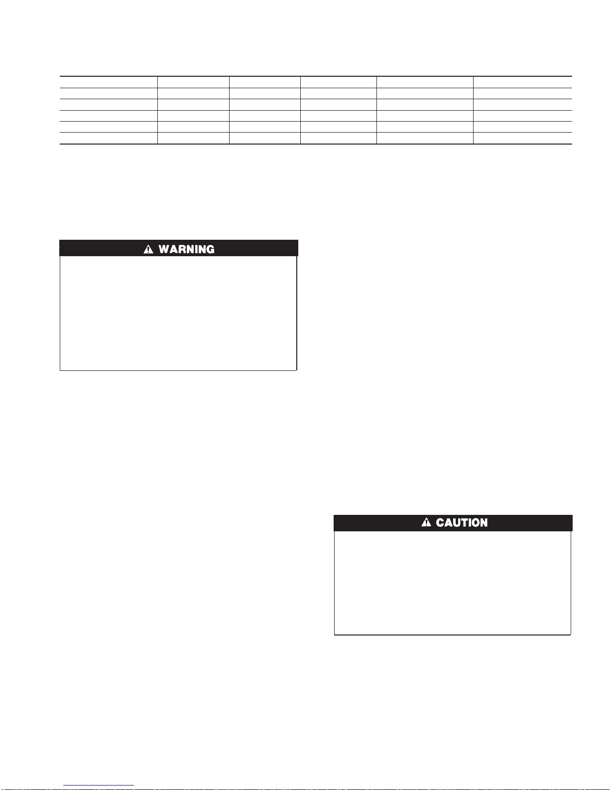
Table 1—Dimensions (IN.)
UNIT SIZE A B C VENT CONN.* SHIP WT. (LB)
070-12/036070 14-3/16 12-9/16 12-11/16 4 126
090-16/048090 17-1/2 15-7/8 16 4 151
110-22/066110 21 19-3/8 19-1/2 4 161
135-22/066135 24-1/2 22-7/8 23 4 177
155-22/066155 24-1/2 22-7/8 23 4 183
* 5” or 6” vent connector may be required in some cases.
3