manuals.online logo
Brands
  1. Home
  2. •
  3. Brands
  4. •
  5. Carrier
  6. •
  7. Furnace
  8. •
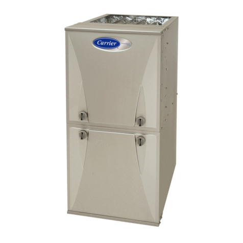
  9. Carrier 58VLR Instructions and recipes

Carrier 58VLR Instructions and recipes

Other manuals for 58VLR

3

Other Carrier Furnace manuals

Carrier 58UHV Series Instructions and recipes

Carrier

Carrier 58UHV Series Instructions and recipes

Carrier 58GS Series Dimensions and installation guide

Carrier

Carrier 58GS Series Dimensions and installation guide

Carrier Performance 59TP5A Series Operation manual

Carrier

Carrier Performance 59TP5A Series Operation manual

Carrier WeatherMate 58STA Guide

Carrier

Carrier WeatherMate 58STA Guide

Carrier 58CLA Instructions and recipes

Carrier

Carrier 58CLA Instructions and recipes

Carrier AGAGC9PNS01D User manual

Carrier

Carrier AGAGC9PNS01D User manual

Carrier AGATWNPME01B User manual

Carrier

Carrier AGATWNPME01B User manual

Carrier UPFLOW INDUCED-COMBUSTION FURNACES 58PAV User manual

Carrier

Carrier UPFLOW INDUCED-COMBUSTION FURNACES 58PAV User manual

Carrier OIL FURNACE 58CMA User manual

Carrier

Carrier OIL FURNACE 58CMA User manual

Carrier A10247 User manual

Carrier

Carrier A10247 User manual

Carrier 820SA Guide

Carrier

Carrier 820SA Guide

Carrier 58 Series User guide

Carrier

Carrier 58 Series User guide

Carrier 379C/HO User manual

Carrier

Carrier 379C/HO User manual

Carrier 58CLA Operation manual

Carrier

Carrier 58CLA Operation manual

Carrier 58ST Guide

Carrier

Carrier 58ST Guide

Carrier 101 Series Installation and user guide

Carrier

Carrier 101 Series Installation and user guide

Carrier 120/C Series Guide

Carrier

Carrier 120/C Series Guide

Carrier 986TC Guide

Carrier

Carrier 986TC Guide

Carrier 58MTB Installation and user guide

Carrier

Carrier 58MTB Installation and user guide

Carrier 58MCA Instructions and recipes

Carrier

Carrier 58MCA Instructions and recipes

Carrier 58TUA Guide

Carrier

Carrier 58TUA Guide

Carrier F97CMN Guide

Carrier

Carrier F97CMN Guide

Carrier OIL FURNACE 58CMA Operation manual

Carrier

Carrier OIL FURNACE 58CMA Operation manual

Carrier 58MCB Instructions and recipes

Carrier

Carrier 58MCB Instructions and recipes

Popular Furnace manuals by other brands

Unitary products group AHV8 UH installation manual

Unitary products group

Unitary products group AHV8 UH installation manual

VERDER CARBOLITE GERO RHF 14/8 Installation, operation and maintenance instructions

VERDER

VERDER CARBOLITE GERO RHF 14/8 Installation, operation and maintenance instructions

Tempstar B Series Service and technical support manual

Tempstar

Tempstar B Series Service and technical support manual

Armstrong EG7H SERIES Installation and maintenance instructions

Armstrong

Armstrong EG7H SERIES Installation and maintenance instructions

Payne PG92ESA Installation, start-up, operating and service and maintenance instructions

Payne

Payne PG92ESA Installation, start-up, operating and service and maintenance instructions

NANOE Zetasinter Operation manual

NANOE

NANOE Zetasinter Operation manual

SUPREME FEM10-M2301CM-A Installation instructions and homeowner's manual

SUPREME

SUPREME FEM10-M2301CM-A Installation instructions and homeowner's manual

Johnson Controls TM9T User's information manual

Johnson Controls

Johnson Controls TM9T User's information manual

Fluke 9118A user manual

Fluke

Fluke 9118A user manual

Lennox EL195UHE Elite Series Unit information

Lennox

Lennox EL195UHE Elite Series Unit information

Intertherm M7RL Series user manual

Intertherm

Intertherm M7RL Series user manual

HDG Pelletmaster 15 Operation manual

HDG

HDG Pelletmaster 15 Operation manual

Nortek MG2S Series installation instructions

Nortek

Nortek MG2S Series installation instructions

VERDER CARBOLITE GERO ABF 8/28 Installation, operation and maintenance instructions

VERDER

VERDER CARBOLITE GERO ABF 8/28 Installation, operation and maintenance instructions

Goodman GMV9 Installation & operating instructions

Goodman

Goodman GMV9 Installation & operating instructions

SUPREME SUP10-M2301C Installation instructions and homeowner's manual

SUPREME

SUPREME SUP10-M2301C Installation instructions and homeowner's manual

Dettson AMT400B34-SM1PMA Installation instructions and homeowner's manual

Dettson

Dettson AMT400B34-SM1PMA Installation instructions and homeowner's manual

Evcon DGD 60 MBH installation instructions

Evcon

Evcon DGD 60 MBH installation instructions

manuals.online logo
manuals.online logoBrands
  • About & Mission
  • Contact us
  • Privacy Policy
  • Terms and Conditions

Copyright 2025 Manuals.Online. All Rights Reserved.

_I_rn to the Expert£
Installation, Start-Up, and
Operating Instructions
NOTE: Read the entire instruction manual before starting the
installation.
TABLE OF CONTENTS
PAGE
SAFETY CONSIDERATIONS ........................ 1
INTRODUCTION .................................. 3
LOCATION ....................................... 3
General ........................................ 3
Location Relative to Cooling Equipment ............... 4
INSTALLATION ................................... 4
Air for Combustion and Ventilation ................... 4
Outdoor Combustion-Air Method .................... 4
Standard- and Known-Air-Infiltration Rate Methods ..... 6
General ......................................... 7
Unconfined Space ............................... 7
Confined Space ................................. 7
Ductwork Recommendations ........................ 7
Venting .......................................... 7
Oil Burner ...................................... 8
Oil Connections .................................. 8
Barometric Draft Control ........................... 9
Electrical Connections .............................. 9
Filters ......................................... 10
START-UP. ADJUSTMENT, AND SAFETY CHECKOUT 12
Operational Checkout ............................. 12
Sequence of Operation ............................ 12
Combustion Check ............................... 13
Fan Adjustment Check ............................ 14
Limit Control Check .............................. 14
For Year-Round Air Conditioning ................... 14
MAINTENANCE .................................. 14
General ........................................ 15
Oil Burner ..................................... 15
Heat Exchanger and Flue Pipe ...................... 15
Blower Removal ................................. 15
Fig. 1 -- 58VLR Low-Boy Oil Furnace
A05024
SAFETY CONSIDERATIONS
Recognize safety information. This is the safety-alert symbol
_. When you see this symbol on the furnace and in
instructions or manuals, be alert to the potential for personal
injury.
Understand the signal words DANGER, WARNING, and
CAUTION. These words are used with the safety-alert symbol.
DANGER identifies the most serious hazards which win result in
severe personal injury or death. WARNING signifies a hazard
which could result in personal injury or death. CAUTION is used
to identify unsafe practices which may result in minor personal
injury or product and property damage. NOTE is used to
highlight suggestions which will result in enhanced installation,
reliability, or operation.
VENT [q
CONN
1
21 1/4" 1
20"
!1
20"
I
UNIT
SIZE
_/////////////////_"
•
wl
1
20"
!
Fig. 2 -- Dimensional Drawing
Dimensions (In.)
FLUE HEIGHT
Width
21-1/4
21-1/4
UNIT DIMENSIONS
Depth
A
53-3/4
60- 5/32
Height
B
31-1/2
34- 3/4
A98009
C
26-1/2
28-11/32
RETURN
OPENING
D
2O
22
SUPPLY
OPENING
E
20
24
VENT
CONNECTION
105-12 5
120-20 6
FIRE, EXPLOSION HAZARD
Failure to follow this warning could result in personal
injury, death, and/or property damage.
Do not store or use gasoline or other flammable vapors and
liquids in the vicinity o1"this or any other appliance. Do not
attempt to start the burner when excess oil has accumulated,
when the furnace is full of vapor, or when the combustion
chamber is very hot.
FIRE, EXPLOSION, ELECTRICAL SHOCK
HAZARD
Failure to follow this warning could result in personal
injury, death, and/or property damage.
These instructions are intended to be used by qualified
personnel who have been trained in installing this type of
furnace.
FIRE, EXPLOSION HAZARD
Failure to follow this warning could result in personal
injury, death, and/or property damage.
For use with grade 1 or 2 fuel oil. Do not use gasoline,
crankcase oil, or any oil containing gasoline!
FIRE, EXPLOSION HAZARD
Failure to follow this warning could result in personal
injury, death and/or property damage.
Never burn garbage or paper in the heating system and
never leave rags, paper, or any flammable items around the
unit.
All local and national code requirements governing installation of
oil burning equipment, wiring, and flue connections must be
followed. Some of the codes (issued by the Canadian Standards
Association,theNationalFireProtectionAgency,and/orthe
AmericanNationalStandardsInstitute)thatmaybeapplicable
are:
ANSI/NFPA31:INSTALLATIONOFOILBURNING
EQUIPMENT
ANSI/NFPA211:CHIMNEYS,FIREPLACES,VENTS,AND
SOLIDFUELBURNINGAPPLIANCES
ANSI/NFPA90B:WARMAIRHEATINGANDAIR
CONDITIONINGSYSTEMS
ANSI/NFPA70:NATIONALELECTRICCODE
CSAB139:INSTALLATIONCODEFOROILBURNING
EQUIPMENT
CSAC22.1:CANADIANELECTRICALCODE
Onlythelatestissuesofthesecodesshouldbeused.andare
availablefromeitherTheNationalFireProtectionAgency,
BatterymarchPark,Quincy,MA02269orTheCanadian
StandardsAssociation,178RexdaleBlvd.,Rexdale,Ontario
M9W1R3.
Thisfurnaceisdesignedforcontinuousreturn-airminimum
temperatureof60°Fdborintermittentoperationdownto55°F
dbsuchaswhenusedwithanightsetbackthermostat.Return-air
temperaturemustnotexceed80_'Fdb.Failuretofollowthese
returnairlimitsmayaffectreliabilityofheatexchangers,motors
andcontrols.(SeeFig.3.)
FRONT
M_80°F
RETURN
AHR MHN60°F
Fig. 3 -- Return-Air Temperature
A06021
INTRODUCTION
The model 58VLR Furnaces are available in 2 sizes. Each size
can be fired at 3 different rates by a simple nozzle change. Unit
58VLR105 covers input ranges from 70,000 to 105,000 Btuh.
Unit 58VLR120 covers input ranges from 119,000 to 154,000
Btuh.
This furnace is a Low-Boy unit. It may be operated only in the
upflowconfiguration. This furnace is not approved for
installation in mobile homes, recreational vehicles, or outdoors.
The furnace is shipped as a packaged unit. complete with burner
and controls. It requires a line voltage (115 vac) connection to
control box, a thermostat hook-up as shown on wiring diagram,
oil line connection(s), adequate duct work, and connection to a
properly sized vent.
The air handling capacity of this furnace is designed for cooling
airflow. Refer to Table 19 or 20 for expected airflows at various
external duct static pressures.
LOCATION
STEP 1--General
ELECTRICAL SHOCK, OR UNIT DAMAGE
HAZARD
Failure to follow this warning could result in property
damage, personal injury or death.
This furnace is not water tight and is not designed for
outdoor installation. This furnace shall be installed in such
a manner as to protect electrical components from water.
Outdoor installation would lead to a hazardous electrical
condition and to premature furnace damage.
PERSONAL INJURY AND UNIT DAMAGE
HAZARD
Failure to follow this caution may result in equipment
damage or improper operation.
This oil furnace may be used for construction heat provided
that:
-The furnace is permanently installed with all electrical
wiring, piping, venting and ducting installed according to
these installation instructions. A return air duct is provided.
sealed to the furnace casing, and terminated outside the
space containing the furnace. This prevents a negative
pressure condition as created by the circulating air blower.
causing a flame roll-out and/or drawing combustion
products into the structure.
-The furnace is controlled by a thermostat. It may not be
"hot wired" to provide heat continuously to the structure
without thermostatic control.
-Clean outside air is provided for combustion. This is to
minimize the corrosive effects of adhesives, sealers and
other construction materials. It also prevents the
entrainment of drywall dust into combustion air, which can
cause fouling and plugging of furnace components.
-The temperature of the return air to the furnace is
maintained between 60"F (13°C) and 80°F (2W"C) with no
evening setback or shutdown. The use of the furnace while
the structure is under construction is deemed to be
intermittent operation per our installation instructions.
-The air temperature rise is within the rated rise range on
the furnace rating plate, and the firing rate has been set to
the nameplate value.
-The filters used to clean the circulating air during the
construction process must be either changed or thoroughly
cleaned prior to occupancy.
-The furnace, ducrwork and filters are cleaned as necessary
to remove drywall dust and construction debris from all
HVAC system components after construction is completed.
-After construction is complete, verify furnace operating
conditions including ignition, input rate, temperature rise,
and venting, according to the manufacturer's instructions.
Table 1--Minimum Clearances to Combustible Materials (In.)
SIDES
BACK
TOP
BOTTOM*
FLUE PIPE
UNIT APPLICATION
Furnace
Supply Plenum and Warm-Air Duct within 6 ft. of Furnace
Service Clearance
Furnace Casing or Plenum
Horizontal Warm-Air Duct Within 6 ft. of Furnace
Horizontally or Below Pipe
Vertically Above Pipe
FRONT
*Floor may becombustible
NOTE: Adequate service clearance should be provided over and abovethese dimensions as required.
LOW - BOY
1
1
19
2
2
0
4
9
8
The required minimum clearances for this furnace are specified in
Table 1.
This furnace is approved for reduced clearances to combustible
construction, therefore, it may be installed in a closet or similar
enclosure. It may be located in a basement or on the same level as
area to be heated. In any case, unit should always be installed
level.
The furnace should be located as close as possible to chimney or
vent in order to keep vent connections short and direct. The
furnace should also be located as near as possible to center of air
distribution system.
STEP 2--Location Relative to Cooling Equipment
When installing furnace with cooling equipment for year-round
operation, the following recommendations must be followed for
series or parallel airflow:
1. In parallel akflow applications, dampers must be provided
to direct air over furnace heat exchanger when heat is
desired and over cooling coil when cooling is desired.
2. In series airflow applications, coil is mounted after furnace
in an enclosure in supply-air stream. The furnace blower
is used for both heating and cooling airflow.
The requirements for combustion and ventilation air depend upon
whether or not the furnace is located in a space having a volume
of at least 50 cubic feet per 1,000 Btuh input rating for all
appliances installed in the space.
• Spaces having less than 50 cubic feet per 1,000 Btuh require the
OUTDOOR COMBUSTION-AIR METHOD.
• Spaces having at least 50 cubic feet per 1,000 Btuh may use the
INDOOR COMBUSTION-AIR, STANDARD- or
KNOWN- AIR-INFILTRATION METHOD.
CARBON MONOXIDE POISONING HAZARD
Failure to follow this warning could result in personal injury
or death.
The operation of exhaust fans, kitchen ventilation fans.
clothes dryers, attic exhaust fans or fireplaces could create a
NEGATIVE PRESSURE CONDITION at the furnace.
Make-up air MUST be provided for the ventilation devices,
in addition to that required by the furnace. Refer to the
Carbon Monoxide Poisoning Hazard warning in the venting
section of these instructions to determine if an adequate
amount of make-up air is available.
UNIT DAMAGE HAZARD
Failure to follow this caution may reduce the life of this
unit.
The coil MUST be installed on air-discharge side of
furnace. Under no circumstances should airflow be such
that cooled, conditioned air can pass over furnace heat
exchanger. This will cause condensation in heat exchanger
and possible failure of heat exchanger. Heat exchanger
failure due to improper installation may not be covered by
warranty.
IMPORTANT: The dampers should be adequate to prevent
cooled air from entering furnace. If manually operated, dampers
must be equipped with a means to prevent operation of either
cooling unit or furnace unless damper is in full cool or heat
position.
INSTALLATION
STEP 1 --Air for Combustion and Ventilation
Provisions for adequate combustion, ventilation, and dilution air
must be provided in accordance with:
• U.S. Installations: Section 8.3 of the NFGC, Air for Combustion
and Ventilation, and applicable provisions of the local building
codes.
•Canadian Installations: Part 7 of the NSCNGPIC, Venting
Systems and Air Supply for Appliances, and all authorities
having jurisdiction.
STEP 2 --Outdoor Combustion-Air Method
1. Provide the space with sufficient air for proper
combustion, ventilation, and dilution of flue gases using
permanent horizontal or vertical duct(s) or opening(s)
directly communicating with the outdoors or spaces that
freely communicate with the outdoors.
2. Fig. 4 illustrates how to provide TWO OUTDOOR
OPENINGS, one inlet and one outlet combustion and
ventilation air opening, to the outdoors.
a. One opening MUST commence within 12" (300 mm) of
the ceiling and the second opening MUST commence
within 12" (300 mm) of the floor.
b. Size openings and ducts per Fig. 5 and Table 2.
c. TWO HORIZONTAL DUCTS require 1 square inch of
free area per 2.000 Btuh (1,100 mm2/kW) of combined
input for all appliances in the space per Fig. 4 and Table
2.
d. TWO OPENINGS OR VERTICAL DUCTS require 1
square inch of free area per 4,000 Btuh (550 mm2/kW)
for combined input of all appliances in the space per
Fig.4 and Table 2.
3.ONEOUTDOOROPENINGrequires:
a.Onesquareinchoffreeareaper3,000Btuh(734
mm2NW)forcombinedinputofallappliancesinthe
spaceperTable2;and
b.Notlessthanthesumoftheareasofallventconnectors
inthespace.
12" MAX
1 SQIN. A
PER 2000 T
BTUH*
DUCTS
TO
OUTDOORS
1SQ IN.
PER 2000
BTUH*
I 12" MAX
CIRCULATING AIR DUCTS DUCT 1SQIN.
TO PER4000
OUTDOORS BTUH*
*Minimum dimensions of 3 in.
NOTE: Use any of the following
combinations of openings:
A&B C&D D&E F&G
A03174
Fig. 4 -- Air for Combustion, Ventilation, and Dilution for
Outdoors
CIRCULATING AIR
DUCTS
I I
I I
I I
INTERIOR
HEATED
SPACE
I I
I I
I I
I
CIRCULATING AIR DUCTS
VENT THROUGH ROOF
U12" !lAX
s
F-_z _-----1SQIN.
coco PER 1000
ca BTUH* IN DOOR
ORWALL
O
O_
LL<
OW UNCONFINED
SPADE
o<
CC! 6" b1[N
ELco (FRONT)t
zco
o- 1 SQIN.
PERlOO0
BTUH* IN DOOR
s ORWALL
o
L12" MAX
* Minimum opening size is 100 sq in. with
minimum dimensions of 3 in.
t Minimum of 3 in. when type-B1 vent is used.
A03175
Fig. 5 -- Air for Combustion, Ventilation, and Dilution
fi'om Indoors
Table 2--Minimum Free Area Required for Each Combustion-Air Opening or Duct to Outdoors
TWO HORIZONTAL DUCTS SINGLE DUCT OR OPENING TWO OPENINGS OR VERTICAL DUCTS
FURNACE (1 SQ. IN./2,000 BTUH) (1 SQ. IN./3,000 BTUH) (1 SQ. IN./4,000 BTUH)
INPUT (1,100 SQ. MM/KW) (734 SQ. MM/KW) (550 SQ. MM/KW)
(BTUH) Free Area of Round Duct Free Area of Round Duct Free Area of Round Duct
Opening and Opening and Opening and Duct
Duct (Sq. In.) (In. Dia) Duct (Sq. In.) (In. Dia) (Sq. In.) (In. Dia)
44,000 22 6 14.7 5 11 4
66,000 33 7 22 6 16.5 5
88,000 44 8 29.3 7 22 6
110,000 55 9 36.7 7 27.5 6
132,000 66 10 44 8 33 7
154,000 77 10 51.3 9 38.5 8
EXAMPLES: Determining Free Area
FURNACE WATER HEATER TOTAL INPUT
110,000 + 30,000 = (140,000 divided by 4,000) = 35.0 Sq. In. for each two Vertical Ducts or Openings
66,000 + 40,000 = (106,000 divided by 3,000) = 35.3 Sq. In. for a Single Duct or Opening
68,000 + 30,000 = (118,000 divided by 2,000) = 59.0 Sq. In. for each of two Horizontal Ducts
Table 3---Minimum Space Volumes for 100 % Combustion, Ventilation, and Dilution from Indoors
OTHER THAN FAN-ASSISTED TOTAL FAN-ASSISTED TOTAL
(1,000's BTUH INPUT RATE (1,000's BTUH INPUT RATE)
ACH 30 40 50 44 66 88 110 132 154
Space Volume (ft.3)
0.60 1,050 1,400 1,750 1,I00 1,650 2,200 2,750 3,300 3,850
0.50 1,260 1,680 2,100 1,320 1,980 2,640 3,300 3,960 4,620
0.40 1,575 2,100 2,625 1,650 2,475 3,300 4,125 4,950 5,775
0.30 2,100 2,800 3,500 2,200 3,300 4,400 5,500 6,600 7,700
0.20 3,150 4,200 5,250 3,300 4,950 6,600 8,250 9,900 11,550
0.10 6,000 8,400 10,500 6,600 9,900 13,200 16,500 19,800 23,100
0.00 NP NP NP NP NP NP NP NP NP
1. For other than fan-assisted appliances, such as a draft 2. For fan-assisted appliances, such as this furnace:
hood-equipped water heater:
Volume- 21_3( f- tother -) -15ft3 f 'fa_n L"'_j
Other Fan ACH 000 Btu/hrt
ACH L1000 Btu/hr Volume
A04002 A04003
Table 3-Minimum Space Volumes were determined by using the following equations from the National Fuel Gas Code ANSI
Z223.I-2002/NFPA 54-2002,8.3.2.2.
If:
Iother = combined input of all other than fan-assisted appliances in Btu/hr
If_n = combined input of all fan-assisted appliances in Btu/hr
ACH = air changes per hour (ACH shall not exceed 0.60.)
The opening shall commence within 12" (300 mm) of the ceiling.
Appliances in the space shall have clearances of at least 1" (25
mm) from the sides and back and 6"' (150 mm) from the front.
The opening shall directly communicate with the outdoors or
shall communicate through a vertical or horizontal duct to the
outdoors or spaces (crawl or attic) that freely communicate with
the outdoors.
Indoor Combustion-Air?) NFPA & AGA
STEP 3 --Standard- and Known-Air-Infiltration Rate
Methods
Indoor air is permitted for combustion, ventilation, and dilution
if the Standard- or Known-Air-Infiltration Method is used.
CARBON MONOXIDE POISONING HAZARD
Failure to follow this warning could result in personal injury
or death.
Many homes require air to be supplied from outdoors for
furnace combustion, ventilation, and dilution of flue gases.
The furnace combustion air supply must be provided in
accordance with this instruction manual.
The Standard Method:
1. The space has no less volume than 50 cubic feet per 1,000
Btuh of the maximum input ratings for all gas appliances
installed in the space and
2. The air infiltration rate is not known to be less than 0.40
air changes per hour (ACH).
The Known-Air-Infiltration Rate Method shall be used if the
infiltration rate is known to be:
1. Less than 0.40 ACH; and
2. Equal to or greater than 0.10 ACH.
Infiltration rates greater than 0.60 ACH shall not be used. The
minimum required volume of the space varies with the number of
ACH and shall be determined per Table 3 or equations 1 and 2.
Determine the minimum required volume for each appliance in
the space and add the volumes together to get the total minimum
required volume for the space.
The following requirements apply to the Standard Method and
to the Known-Air-Infiltration Rate Method.
1. Adjoining rooms can be considered part of aspace if:
a. There are no closable doors between rooms.
b. Combining spaces on same floor level. Each opening
shall have free area of at least 1 in.2/1.000 Btuh (2,000
mm-/kW) of the total input rating of all gas appliances in
the space, but not less than 100 in. 2 (0.06 m2). One
opening shall commence within 12" (300 mm) of the
ceiling and the second opening shall commence within
12" (300 mm) of the floor. The minimum dimension of
air openings shall be at least 3 in. (80 mm). (See Fig. 5.)
c. Combining space on different floor levels. The volumes
of spaces on different floor levels shall be considered as
communicating spaces if connected by one or more
permanent openings in doors or floors having free area of
at least 2 in.2/1,000 Btuh (4,400 mm2_W) of total input
rating of all appliances.
2. An attic or crawl space may be considered a space that
freely communicates with the outdoors provided there are
adequate permanent ventilation openings directly to
outdoors having free area of at least 1-in.2/4,000 Btuh of
total input rating for all appliances in the space.
3. In spaces that use the Indoor Combustion-Air Method.
infiltration should be adequate to provide air for combus-
tion, permanent ventilation and dilution of flue gases.
However. in buildings with unusually tight construction.
additional air MUST be provided using the methods de-
scribed in the Outdoor Combustion-Air Method section.
Unusually tight construction is defined as construction
with:
a. Walls and ceilings exposed to the outdoors having a con-
tinuous, sealed vapor barrier. Openings are gasketed or
sealed; and
b.Doorsandopenablewindowsareweatherstripped:and
c.Otheropeningsarecaulkedorsealed.Theseinclude
jointsaroundwindowsanddoorframes,betweensole
platesandfloors,betweenwall-ceilingjoints,between
wallpanels,atpenetrationsforplumbing,electricaland
gaslines,etc.
Combinationof Indoor and Outdoor Air
1. Indoor openings shall comply with the Indoor
Combustion-Air Method below: and
2. Outdoor openings shall be located as required in the
Outdoor Combustion-Air Method mentioned
previously; and
3. Outdoor openings shall be sized as follows:
a. Calculate the Ratio of all indoor space volume divided by
required volume for Indoor Combustion-Air Method
below.
b. Outdoor opening size reduction factor is 1 minus the
ratio in a. above.
c. Minimum size of Outdoor openings shall be the size
required in Outdoor Combustion-Air Method above
multiplied by reduction Factor in b. above. The
minimum dimension of air openings shall be not less than
3 in. (80 mm).
STEP 4 --Ductwork Recommendations
CARBON MONOXIDE POISONING HAZARD
Failure to follow this warning could result in personal injury
or death.
When supply ducts carry air circulated by furnace to areas
outside spaces containing furnace, return air MUST also be
handled by a duct sealed to furnace casing and terminating
outside space containing furnace.
UNIT MAY NOT OPERATE
Failure to follow this caution may result in intermittent unit
operation.
Return-air grilles and warm air registers MUST NOT be I
Iobstructed.
The proper sizing of warm air ducts is necessary to ensure
satisfactory furnace operation. Ductwork should be in accordance
with the latest editions of NFPA-90A (Installation of Air
Conditioning and Ventilating Systems) and NFPA-90B (Warm
Air Heating and Air Conditioning Systems) or Canadian
equivalent.
The supply ductwork should be attached to flanged front opening
provided at discharge end of furnace. The return-air duct work
should be attached to flanged rear opening of furnace. See Fig. 2
for dimensions of these openings.
NOTE: The back (blower access opening) should not be used for
return air.
The following recommendations should be followed when
installing ductwork:
1. Install locking-type dampers in all branches of individual
ducts to balance out system. Dampers should be adjusted
to impose proper static at outlet of furnace.
2. A flexible duct connector of noncombustible material
should be installed at unit on both supply- and return-air
systems. In applications where extremely quiet operation
is necessary, the first 10 ft. (if possible) of supply and
return ducts should be internally lined with acoustical
material.
3. In cases where return-air grille is located close to fan inlet,
there should be at least one 90 ° air turn between fan inlet
and grille. Further reduction in sound level can be
accomplished by installing acoustical air turning vanes or
lining duct as described in item 2 above.
4. When a single air grille is used, duct between grille and
furnace must be the same size as return opening in furnace.
STEP 5 --Venting
Venting of furnace should be to the outside and in accordance
with local codes or requirements of local utility.
OIL-FIRED APPLIANCES SHALL BE CONNECTED TO
FLUES HAVING SUFFICIENT DRAFT AT ALL TIMES TO
ENSURE SAFE AND PROPER OPERATION OF
APPLIANCE.
For additional venting information, refer to ANSI/NFPA 211
Chimney, Fireplaces, Vents. and Solid Fuel Burning, Appliances
and/or CSA B139 Installation Code.
This furnace is certified for use with Type "L" vent (maximum
flue gas temperature 575 °F).
VENT SYSTEM INSPECTION
Before furnace is installed, it is highly recommended that any
existing vent system be completely inspected.
n
CARBON MONOXIDE POISONING HAZARD
Failure to follow this warning could result in property
damage, personal injury, or death.
The following steps shall be followed for each appliance
connected to the venting system being placed into
operation, while all other appliances connected to the
venting system are not in operation:
1. Seal any unused openings in venting system.
2. Inspect the venting system for proper size and horizontal
pitch, as required in the NFPA31. Installation of Oil
Burning Equipment and the Canadian Standard B140.4 Oil
Fired Warm Air Furnaces. Determine that there is no
blockage or restriction, leakage, corrosion and other
deficiencies which could cause an unsafe condition.
3. As far as practical, close all building doors and windows
and all doors between the space in which the appliance(s)
connected to the venting system are located and other
spaces of the building.
4. (?lose fireplace dampers.
5. Turn on clothes dryers and any appliance not connected
to the venting system. Turn on any exhaust fans, such as
range hoods and bathroom exhausts, so they are operating
at maximum speed. Do not operate a summer exhaust fan.
6. Follow the lighting instructions. Place the appliance
being inspected into operation. Adjust the thermostat so
appliance is operating continuously.
7. Test for spillage from draft-hood equipped appliances at
the draft-hood relief opening after 5 minutes of main burner
operation. Use the flame of a match or candle.
8. If improper venting is observed during any of the above
tests, the venting system must be corrected in accordance
with the NFPA31, Installation of Oil Burning Equipment
and the Canadian Standard B140.4 Oil Fired Warm Air
Furnaces.
9. After it has been determined that each appliance
connected to the venting system properly vents when tested
as outlined above, return doors, windows, exhaust fans,
fireplace dampers and any other gas-fired burning
appliance to their previous conditions of use.
For any chimney or vent, this should include the following:
1. Inspection for any deterioration in chimney or vent. If
deterioration is discovered, chimney must be repaired or
vent must be replaced.
2. Inspection to ascertain that vent system is clear and free of
obstructions. Any blockage must be cleared before
installing furnace.
3. Cleaning chimney or vent if previously used for venting a
solid fuel burning appliance or fireplace.
4. Confirming that all unused chimney or vent connections
are properly sealed.
5. Verification that chimney is properly lined and sized per
the applicable codes. (Refer to list of codes in Safety
Considerations section.)
MASONRY CHIMNEYS
This furnace can be vented into an existing masonry chimney.
This furnace must not be vented into a chimney servicing a solid
fuel burning appliance. Before venting furnace into a chimney,
the chimney MUST be checked for deterioration and repaired if
necessary. The chimney must be properly lined and sized per
local or national codes.
If furnace is vented into a common chimney, the chimney must
be of sufficient area to accommodate the total flue products of all
appliances vented into chimney.
The following requirements are provided for a safe venting
system:
1. Be sure that chimney flue is clear of any dirt or debris.
2. Be sure that chimney is not servicing an open fireplace.
3. Never reduce pipe size below the outlet size of furnace.
(See Fig. 2.)
4. All pipe should be supported using proper clamps and/or
straps. These supports should be at least every 4 ft.
5. All horizontal runs of pipe should have at least 1/4 in. per
ft of upward slope.
6. All runs of pipe should be as short as possible with as few
turns as possible.
7. Seams should be tightly joined and checked for leaks.
8. The flue pipe must not extend into chimney but be flush
with inside wall.
9. The chimney must extend 3 ft above highest point where
it passes through the roof of a building and at least 2 ft
higher than any portion of a building within a horizontal
distance of 10 ft. It shall also be extended at least 5 ft
above highest connected equipment flue collar.
10. Check local codes for any variance.
FACTORY-BUILT CHIMNEYS
Listed factory-built chimneys may be used. Refer to chimney
manufacturer's instructions for proper installation.
STEP 6 --Oil Burner
This furnace is supplied with a high-pressure atomizing retention
head-type burner (for use with grade 1 or 2 Fuel Oil). The Riello
oil burner operates with a pre-purge period of 10 sec and a safety
timing of 5 sec. The burner flange is factory installed for an
insertion length of 3-3/4-in. The oil pump is set to operate on a
single line system. To operate on a two-line system the by-pass
plug must be installed.
STEP 7 --Oil Connections
UNIT COMPONENT HAZARD
Failure to follow this caution may result in unit
component damage.
This burner is shipped with the oil pump set to operate on
a single line system. To operate on a two-llne system the
by-pass plug must be installed. Do not operate a single
line system with the by-pass plug installed. Operating a
single line system with the by-pass plug installed will
result in damage to the pump shaft seal. Pump pressure
must be set at time of burner start-up. A pressure gauge is
attached to the PRESSURE PORT for pressure readings.
Two PIPE CONNECTORS are supplied with the burner
for connection lines to burner pipe connectors. All pump
port threads are British Parallel Thread design. Direct
connection of NPT threads to the pump will damage the
pump body. Riello manometers and vacuum gauges do
not require any adapters, and can be safely connected to
the pump ports. An NPT (metric) adapter must be used
when connecting other gauge models.
Completeinstructionsforinstallingfueloilpipingcanbefound
inoilburnerInstallationInstructionsincludedwithfurnace.
Oillineentryholesareprovidedinsidepanels.Twoholesare
providedineachlocationsothata2-pipesystemmaybeusedif
desired.
Anoilfiltershouldbeusedwithalloilburnersandshouldbe
installedasclosetoburneraspossible.
STEP 8 --Barometric Draft Control
Tire barometric draft control shipped with furnace MUST be used
with furnace to ensure proper operation. Instructions for installing
control are packed with control.
STEP 9 --Electrical Connections
ELECTRICAL SHOCK HAZARD
Failure to follow this warning could result in personal
injury or death.
The unit cabinet must have an uninterrupted or unbroken
electrical ground. A green ground screw is provided in
control box for this connection.
115-V WIRING
Before proceeding with electrical connections, make certain that
voltage, frequency, and phase correspond to that specified on unit
rating plate. Also. check to be sure that service provided by utility
is sufficient to handle load imposed by this equipment. Refer to
rating plate or Table 9 for equipment electrical specifications.
Make all electrical connections in accordance with National
Electrical Code (NEC) ANSI/NFPA 70-2001 and any local codes
or ordinances that might apply. For Canadian installations, all
electrical connections must be made in accordance with Canadian
Electrical Code CSA (722.1 or sub-authorities having
jurisdiction.
FIRE HAZARD
Failure to follow this warning could result in personal
injury, death, or property damage.
Do not connect aluminum wire between disconnect switch
and furnace. Use only copper wire.
The control system depends on correct polarity of power supply.
Connect HOT wire (H) and NEUTRAL wire (N) as shown in
Fig. 6.
A separate line voltage supply MUST be used with a fused
disconnect switch or circuit breaker between main power panel
and unit. (See Fig. 6.)
Metallic conduit (where required/used) may terminate at side
panel of unit. It is not necessary to extend conduit inside unit
from side panel to control box.
When replacing any original furnace wiring, use only 105°C No.
14 AWG copper wire.
Table 4--Electric Data
UNIT SIZE MAX UNIT
AMPS
VOLTS-
HERTZ-
PHASE
115-60-1
115-60-1
OPERATING VOLTAGE RANGE
Max.* Min.*
132 104
132 104
MIN. WIRE
GAUGE MAX WIRE
LENGTH (FT.)t
105-12 12.2 14 26
120-20 15.7 12 26
Permission limits of voltage range at which unit will operate satisfactorily.
t Length shown is as measured 1 way along wire path between unit and service panel for maximum 2 % voltage drop.
$ Time-delay fuse is recommended
MAX FUSE OR
CKT BKR
AMPS$
15
20
LADDER WRN_ DIAGRAM DIP SWlT('b_ ADJ{ STEMENT CHART
FOR [NP_JT 050 _0 [375 USDPH
A05391
Fig. 6 -- Wiring Diagram
24-V WIRING
Instructions for wiring thermostat (field supplied) are packed in
thermostat box. Make thermostat connections as shown in
Figures 7 to 10 at 24-v terminal board on electronic control
board. Thermostat wire connections at R and W are the minimum
required for oil heating operation.
ACCESSORY INSTALLATION
1. General
When installing optional accessories to this appliance,
follow manufacturer's Installation Instructions included
with accessory. Other than wiring for thermostat, wire with
a minimum of type "T'insulation (63°F rise) must be used
for accessories.
2. Auxiliary Terminals
The HUM 120 VAC terminals on the electronic control
board are tied directly to the #8 pin of the 9 pin connector
and provide a 120 VAC signal whenever the burner is
energized. (See Fig. 6.) Supplementary 120 VAC and
neutral terminals can be used for accessory wiring. See
Electronic Air Cleaner and Humidifier sections for further
information.
3. Electronic Air (;leaner Connections
When using an electronic air cleaner with variable-speed
oil-fired furnaces, use an Airflow Sensor kit. As the air
cleaner is connected to constant 120 VAC power, the
airflow sensor turns on the electronic air cleaner when the
furnace blower is operating.
4. Humidifier/Humidistat Connections
To ensure humidifier will operate properly, use HUM
output of Humidistat Control to control humidifier
operation. A 24-VAC signal can be connected from the W
and C on terminal block connections on the electronic
board or a 120 VAC signal from the "HUM 120 VAC'
terminal when primary heating source is used. (See
Figures 6-10.)
5. Dehumidify Capability with Standard Humidistat
Connection
Latent capabilities for systems using the variable-speed
oil-fired furnaces are better than average systems. If
increased latent capacity is an application requirement, the
field wiring terminal block provides connection terminals
for use of a standard humidistat.
The variable-speed oil-fired unit will detect the
humidistat contacts opening on increasing humidity and
reduce its airflow to approximately 85% of nominal
cooling mode airflow. This reduction will increase the
system latent capacity until the humidity falls to a level
which causes the humidistat contacts to close. When the
contacts close, the airflow will return to 100% of the
selected cooling airflow. To activate this mode, remove the
Jumper between DH and R of the electronic board and
wire in a standard humidistat.
STEP 10 --Filters
FIRE, CARBON MONOXIDE POISONING
HAZARD
Failure to follow this warning could result in personal
injury, or death.
Never operate unit without a filter or with filter access door
removed.
An internal filter rack is provided as standard equipment with
furnace and is located in blower compartment. A sufficient
clearance should be provided for air filter access. Refer to Table
10 for filter rack flange dimensions for return air duct.
Table 5--Filter Size (In.) and Quantity
RETURN SUPPLY
AIR FILTER
UNIT SIZE SIZE OPENING OPENING
SIZE SIZE
105-12 (2) 12 X 20 20 X 20 20 X 20
120-20 (2) 16 X 20 22 X 20 24 X 20
10