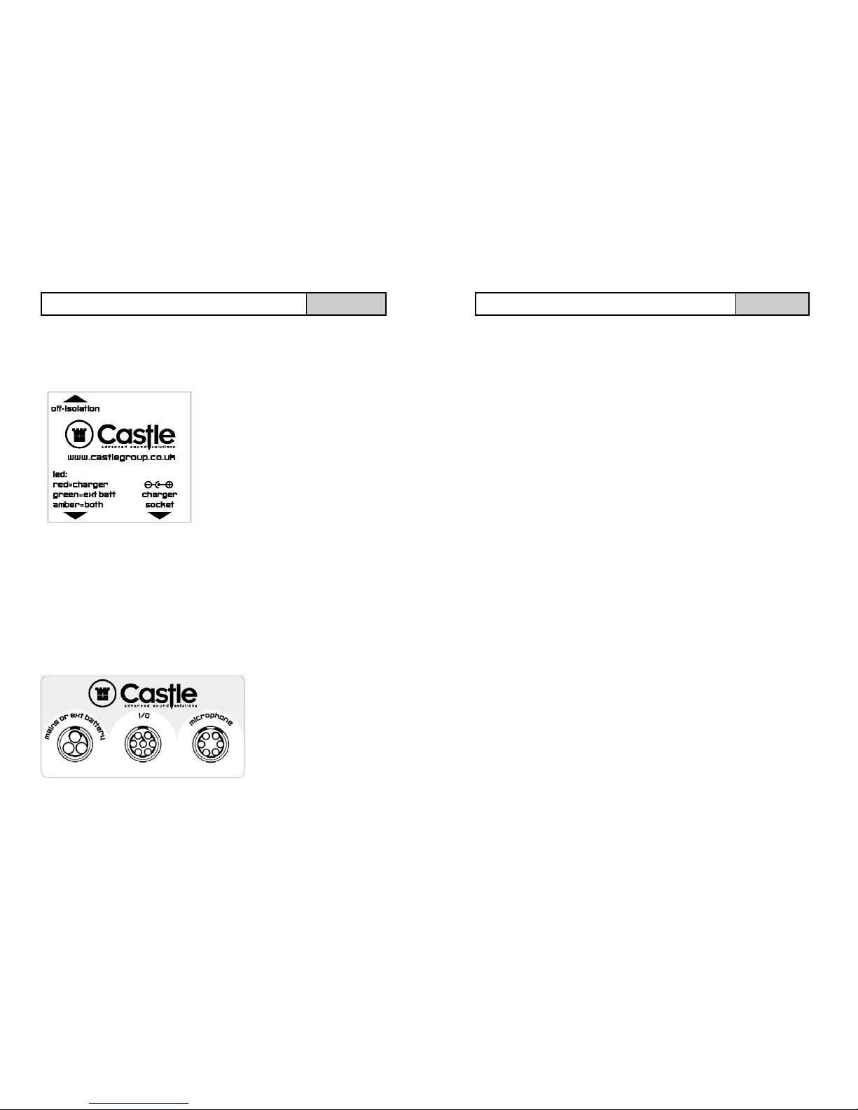
Castle group KA018 User manual

HB/1018/006/A5 Issue C
NOTES

Thank you for buying a Castle product, I am sure you will find both the goods
and the service to be of the highest quality but if not, then please feel free to
write to me personally and I will ensure that your needs are dealt with
immediately.
This manual is designed to show you the operation of the goods you have
purchased. If you would like to become a competent person in the eyes of the
law, then you may like to know more about our Competent persons training
courses, which cover a wide variety of noise assessment tasks.
It is my intention for Castle Group Ltd to provide a complete range of Noise and
Vibration products and Services of the highest standard. If you would like to
know more about any of our other products and services then please visit our
web site at www.castlegroup.co.uk or telephone on +44(0)1723 584250.
Simon Bull
Sales and Marketing Director
NOTES

NOTES PRECAUTIONS
•Only operate the case as described in this manual.
•This manual assumes that the manuals for each individual instrument and
accessories have been read. Read this manual in full before using your
equipment.
•The charge in the batteries supplied with your KA018 can cause severe injury
even death if misused. Take extreme care not to short the battery terminals
with any conductive objects. During operation, always ensure the Air Tight Valve
on the Front of your KA018 Case is not tightly fastened.
•Leave your KA018 kit to temperature adjust for at least 2 Hours when
transferring use from a cold environment to warmer.
•Turn OFF the Isolation Switch to prevent discharge of the batteries in the KA018
if it is not in use.
•Do not let any conductive objects, such as wire or metal scraps get into the unit.
•Care should be taken when closing the case lid to ensure that no cables are
trapped as this will damage the cables.
•Do not try to disassemble the control box, wiring or attempt any repairs as this
may cause injury and will invalidate your warranty. Take a note of the condition of
the case and contact your authorised Castle service station if a problem arises.
•Do not use any solvents or cleaning agents on the case. Use only a soft dry cloth
or a soft cloth lightly moistened with water when necessary.
•To ensure continued precision performance of your instrument have it checked
and serviced at regular intervals. It is recommended that the case be sent when
instruments are returned for calibration.
•As this kit is heavy, please take care whilst lifting and transporting.

TABLE OFCONTENTS
Introduction / Kit Contents....................................................................1
Getting Started..............................................................................................2
Case Layout ....................................................................................................3
Case Connectors And Control Box .....................................................4
Batteries...........................................................................................................5
Battery Removal...........................................................................................5
External Battery Pack And Power Supply ........................................6
Printing..............................................................................................................6
Pro DX Sound Meter Calibration .........................................................7
DAT General Information .........................................................................8
Setting DAT Clock ........................................................................................8
Recording DAT Reference Tone .................................................. 9,10
Pro DX Range Setup ...............................................................................10
Pro DX Weightings Setup ....................................................................11
Pro DX Setup For DAT Recording....................................................12
DAT Remote Switch ................................................................................13
DAT Trouble Shooting.............................................................................13
Attaching The Microphone To MW400 .......................................14
Attaching The Microphone To MW401 ............................... 15,16
Procedure For Noisy Neighbour Recording................................17
Additional Options.....................................................................................18
Trouble Shooting .......................................................................................18
Warranty and After Sales Service ...................................................19
Accessories .................................................................................................20
Technical Specifications ........................................................................21
Notes...............................................................................................................22
TECHNICAL SPECIFICATIONS
Operating Voltages And Current Consumption
GA131 Sound Level Meter
Voltage = 9V
Current = 180mA
KA018 Control Box
Current = 20mA
GA505 Printer
Voltage = 6.5V
Current = 250mA
GA504 DAT
Voltage = 6.5V
Current = 200mA
Standby Current = 1mA
Battery Life
Approximately 150 Hours Continuous With Full Charge
Approximate Weights
12V 17Ah Battery = 6.1 Kg
KA018 Empty Case = 5.0 Kg
KA018 Combined Overall = 19.5 Kg
AC output
0.953V rms at full scale deflection on each range into loads > 10K
Ohms.
Output is short circuit protected and is not affected by Weightings.
Ambient Operating Conditions
Temperature -10ºC to +50ºC
Relative Humidity30 to 90%
21

Spare Parts & Accessories Codes
GA505...............................................................................................................................Thermal Printer
GA504..................................................................................................................................DAT Recorder
ZL2093-03 ............................................ Microphone Extension Cable - 3 metres
ZL2093-10 .......................................... Microphone Extension Cable - 10 metres
ZL2093-20 .......................................... Microphone Extension Cable - 20 metres
ZL2093-30 .......................................... Microphone Extension Cable - 30 metres
MC1TP1................................................................................Microphone Clip with Tripod Adapter
MW400 ....................................................... Short Term Weatherproof Windshield Assembly
MW401 ................Long Term Weatherproof Windshield Assembly with De–Humidifier
CPGA503...................................................................................................Thermal Paper for GA505
REMBUTT2 .............................................................................................. Remote Button for GA504
KA018BATT ................................................................................... Spare Battery for KA018 Case
PC007............................................................................................................dBDataPRO PC Software
ZL1102-02 ......................................................................................................... KA018 PC Link Cable
ZL1063-01 ................................................................................................... KA018 AC Output Cable
PSU3.................................................................................................... KA018 12V DC Power Supply
ZL1096-01 .........................................................................................KA018 External Power Cable
PSU4................................................................................................................ KA018 Battery Charger
20
INTRODUCTION
The KA018 Weatherproof Case is part of Castle’s Pro-DX meter accesso-
ries and has been designed to allow outdoor and long term logging capabilities
with optional sound recording to a Digital Audio Tape (DAT) recorder.
This manual contains complete operating instructions for the above named
instrument, read it carefully and you will quickly become familiar with your
instrument. If you have problems with the operation of the instrument please
call Castle Group Ltd on either:-
+44 (0)1723 584250 Telephone
+44 (0)1723 583728 Fax
www.castlegroup.co.uk Web site
KA018 PART CONTENTS
Your KA018 is supplied as standard with the following parts :-
•KA018 Case With Integrated Control Box
•2 * 12V 17AH Batteries*
•External 12V DC Power Supply
•External Power Connection Lead
•Battery Charger*
Although other accessories may be present in your KA018, these are ordered
independently.
*Noisy Neighbour kits are supplied without batteries and charger.
1

GETTING STARTED
Firstly your KA018 case is shipped with your batteries disconnected.
Before operation using the batteries you must first re-connect them. To do
this simply lift out the foam using the handles provided and plug the bat-
tery connectors into the mating connectors in the cable cut out. The connec-
tors are keyed so you cannot plug them the wrong way around. (Note that
shipped batteries may require charging before use)
Secondly, the Battery Isolation Switch is OFF when shipped, this will need
switching ON before the batteries can be used as a power source. Please see
page 4 for further information.
As the DAT is an additional option, this manual refers to setting up the case
with the DAT recorder. Since this manual covers the operating instructions
for the full capabilities of the case the shaded areas of the title serves to inform
the user which functions are being described on your case.
As an example the title below informs you that this function and its associated
text is only applicable to the DAT.
Example Title DAT
2
Warranty and After Sales Service
Castle Group Ltd design and manufacture precision instruments, which if treated
with reasonable care and attention should provide many years of trouble free
service.
In the event of a fault occurring, during the warranty period, the instrument should
be returned to Castle Group Ltd, in its original packaging, or to an authorised
agent. Please enclose a clear description of the fault or symptom.
Details of the warranty cover are available from Castle Group Ltd or an
authorised agent.
All instruments are designed to meet rigid British and International
Standards. An annual calibration is recommended to ensure that these high
standards are maintained. This is particularly important for cases in which
instrument readings are to be used in litigation or compliance work.
For warranty and service return to:
The Service Department
Castle Group Ltd
Salter Road
Cayton Low Road Industrial Estate
Scarborough
North Yorkshire
YO11 3UZ
Telephone +44 (0)1723 584250
Fax +44 (0)1723 583728
Web: www.castlegroup.co.uk
Any misuse or unauthorised repairs will invalidate the warranty.
Damage caused by faulty or leaking batteries is not covered by the warranty.
19

dBDataPRO Software & KA018 PC Link Cable
This cable plugs into the socket labelled ‘I/O’ on the KA018 case allowing
you to upload saved data to your PC using the required software
‘dBDataPRO’. This allows you to easily view log information either graphically
or as text, save the data in your preferred format and also print on your PC
printer.
KA018 AC Output Cable
This cable plugs into the socket labelled ‘I/O’ on the KA018 case allowing
you to measure the AC signal level on test equipment.
See ‘Spare Parts & Accessory Codes’ on page 20 for order code details.
Not Printing
Ensure the printer is ONLINE indicated by a solid GREEN LED on the top face
of the printer. The solid RED LED indicates the printer is OFFLINE. Press
the ONLINE / OFFLINE key to toggle between ONLINE or OFFLINE.
Ensure the Printer Power Switch is in the ON position. This is a slide switch
located on the left side of the printer.
18
ADDITIONAL OPTIONS ALL
TROUBLE SHOOTING ALL
Lower Section
The batteries sit in the foam cut outs as shown below, cut outs are also
provided to hold the battery connections and internal wiring.
Upper Section
The instruments and control box are situated in the upper section as indicated
below.
CASE LAYOUT ALL
12V Battery 12V Battery
Foam
Cut-outs to hold wiring
Pro-DX Sound Level Meter
Control Box
Printer
Calibrator
DAT Recorder
3

4
Control Box
The control box sits inside the case and houses the electronics. The control box
should not be opened by anyone other than an approved Castle service engineer.
The isolation switch should be ON (indicating BLUE) when the case is in use and
switched off when the case is not in use,
for safe storage and to prevent battery
discharge.
The LED on the control box will illuminate
RED when the Charger is plugged in.
The LED will illuminate GREEN when an
external Battery Pack or external Power
Supply is plugged into the case.
If the LED illuminates AMBER then both the
Charger and External Power are being
used.
CAUTION:
Never use the ISOLATION switch to Turn OFF the instruments, always
shut down as outlined in the instruments operating manual. Doing so may result
in data loss or corruption.
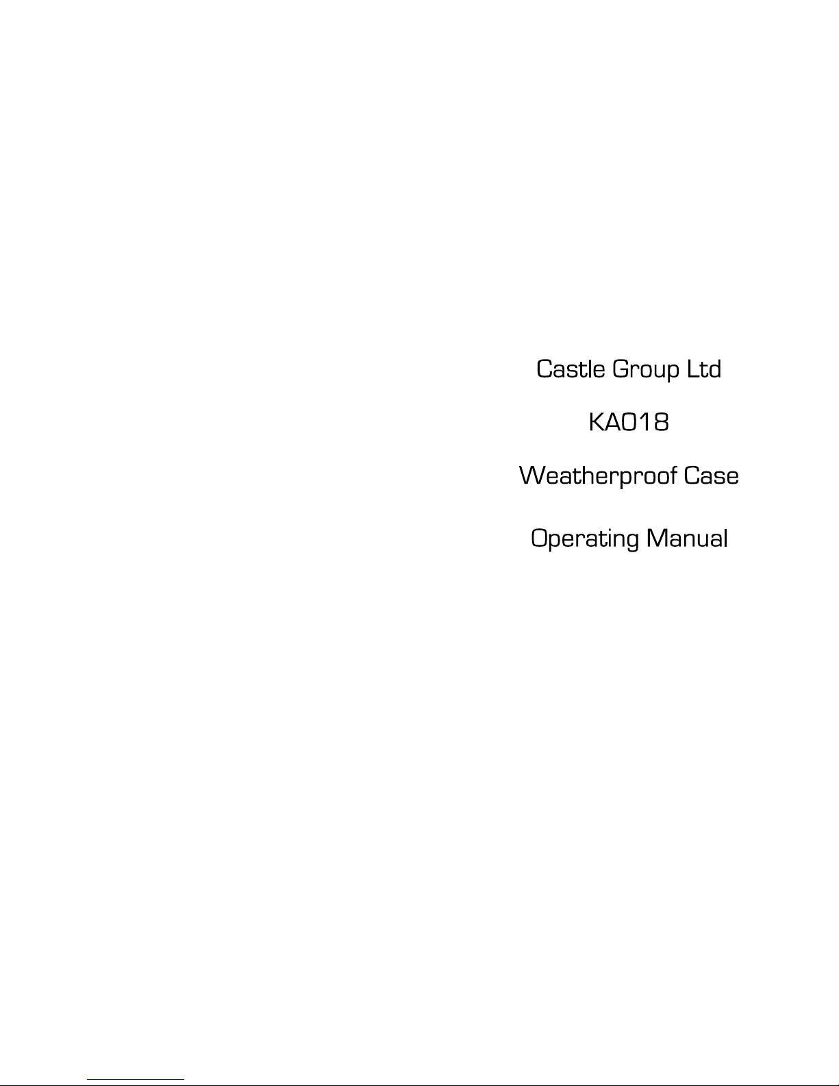
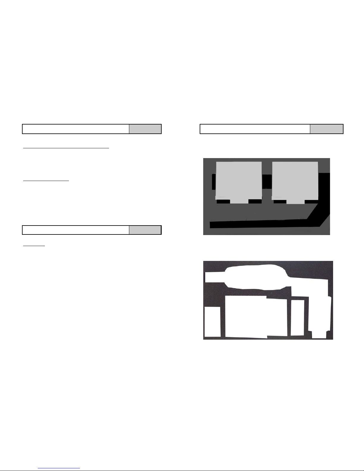
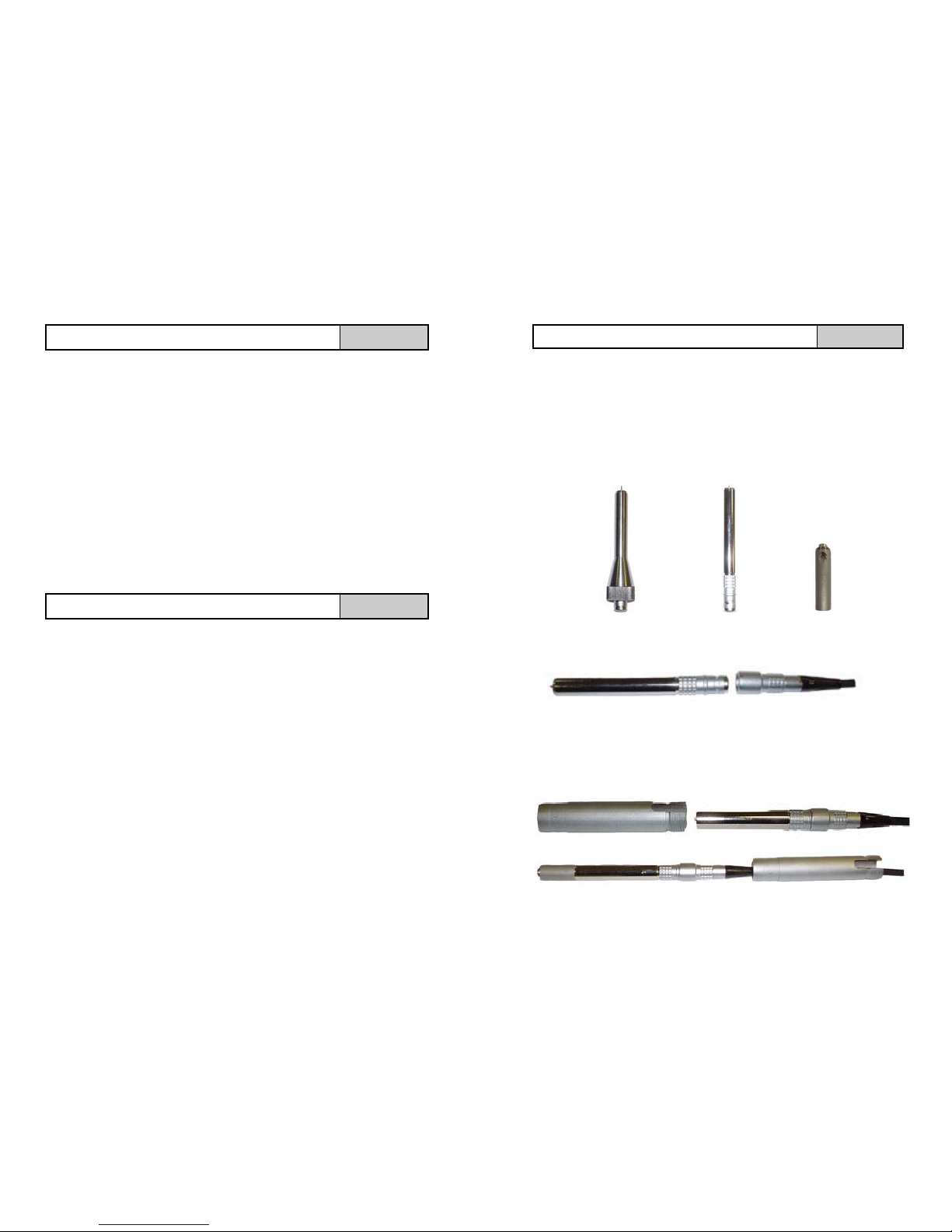
Case Sockets
DO NOT TWIST PLUGS TO CONNECT OR DISCONNECT FROM THE KA018
No turning is required to fit or remove a plug, simply push to fit or pull to
remove.
Please note that each socket is keyed, to fit a plug line up the RED identification
mark on both the socket and
plug.
Plugs will only fit into the
correct sockets. Plugs should
not be forced or damage to the
connector pins may occur.
CASE CONNECTORS AND CONTROL BOX ALL
This section is a guide highlighting the procedure required to make
recordings. It is required that you read this manual fully and refer to
other manuals as required.
Ensure that the 12V batteries are connected or alternatively if you wish to
power the KA018 kit from the mains plug the power lead into the socket
labelled ‘mains or ext battery’.
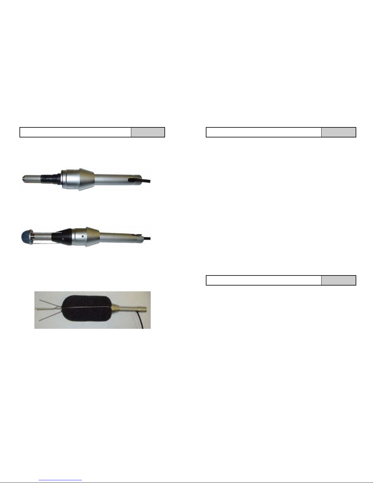
Plug your microphone into the microphone extension lead and attach the
microphone to the MW400 as described on page 14. Now attach the
microphone extension lead into the socket labelled ‘microphone’ on the
KA018 case.
Plug the DAT Remote Switch into the socket labelled ‘I/O’ on the KA018
case.
Switch the control box Battery Isolation Switch to ON (indicating Blue) if you
are powering your kit via the mains this switch position is overridden.
Power on the Pro DX Sound Level Meter and proceed to calibrate the
instrument as described on page 7.
Set the Clock as described on page 8 and then record a Reference Tone on
the tape as described on page 9.
Set the range on your Pro DX Sound Level Meter to the initial recommended
range of 15 – 90dB as described on page 10.
Set the weightings on your Pro DX Sound Level Meter to the recommended
settings as described on page 11.
Activate the DAT option on the Pro DX Meter and select the sound level to
automatically start recording on the DAT machine. This procedure is
described on page 12. An initial recommended level for automatic recording
is 85dB.
Close your KA018 case lid and ensure that the air valve near the case handle
is not fully tightened.
Finally position the KA018 kit / cables and microphone in a safe and secure
manner such as to minimise any possible hazard and leave to record.
PROCEDURE FOR NOISY NEIGHBOUR RECORDING DAT
17

16
ATTACHING THE MICROPHONE TO THE MW401 WINDSHIELD
Step 3
Carefully push the pre-amplifier through the MW401 pre-amplifier clamp until
the de-humidifier and 10mm of the pre-amplifier are visible. Now tighten the
clamp into place using the allen key provided with your kit.
Step 4
Attach the microphone capsule over the de-humidifier unit and then place the
MW401 rain guard over the pre-amplifier assembly. Fasten using the supplied
allen key.
Step 5
Attach the windshield holder over the assembly and fasten using the allen key,
now place the windshield into position. Finally pull the extension cable through
the slot in the stem and screw the tripod adaptor into place.
The KA018 uses two sealed 12V, 17 Ampere Hour, rechargeable lead acid
batteries. Only use the batteries supplied by Castle and always ensure if
replaced that they are inserted with the terminals to the top. For safety
precautions never operate the KA018 kit upside down.
For safe charging of the batteries the following points must be adhered to:
•Only charge indoors
•Never close the KA018 case lid whilst charging
•Use only the supplied charging unit
To charge the case batteries, firstly ensure the above criteria are met. Ensure
the Battery Disconnect Switch is ON (indicating Blue) and insert the charging
plug into the control box socket labelled “Charge”. Charging both batteries
completely, if depleted may take approximately 14 Hours. When your charger
unit illuminates Green then charging is complete. (Refer to the charger manual
for more detail if required).
The KA018 kit can only be powered from the external battery pack or external
power supply connector whilst the batteries are being charged.
To reduce the weight of the KA018 the kit may be powered using one battery
only, however this may cause an unbalance when carrying the case. The
operational time will also reduce by approximately one half.
Operational life of the batteries, on continuous use, will be approximately 6 days.
This time will vary depending on whether the case printer and DAT are used
during operation, and also on the initial battery charge. Extensive use of either
the printer or DAT machine will reduce the time the KA018 Kit will operate for,
however the batteries may be removed and replaced whilst the KA018 is
running and is recommended for long running applications.
To replace the batteries, perform the following procedure:
♦Unplug and remove the left side battery
♦Replace and connect the charged left side battery
♦Unplug and remove the right side battery
♦Replace and connect the charged right side battery
5
BATTERIES ALL
BATTERY REMOVAL ALL

The KA018 kit may be powered from either the supplied Castle 12V DC Power
Supply or from an optional external Castle Battery Pack.
To use any external power source simply plug it into the ‘Mains / Ext Batt’
Connector on the KA018 case and remove when finished. This procedure will
not interrupt your instruments operation if your batteries are charged and
connected correctly.
The position of the battery isolation switch will not hinder operation with either
the external 12V DC Power Supply or the optional External Batteries, however
the isolation switch will need to be ON for un-interruptible operation between
Internal Batteries and External Supply.
For safety reasons only use the supplied Castle DC Power Supply and optional
Castle Battery Pack.
The power switch on the printer can be left on at all times and the printer’s
internal battery can be removed when used in a KA018.
With the GA505 printer plugged into the KA018, power is automatically
provided to the printer when data is sent from the instrument. This means that if
the batteries are not installed in the printer or if they are flat, printing will still be
possilbe.
The supplied GA505 printer will operate using the power supplied from your
KA018 kit as with your Pro DX Sound Level Meter. The printer is only powered
when print information is sent to the printer. When the print job is finished the
printer will power down again.
To ensure printing runs smoothly ensure that the power supply and 9 pin D
connector are plugged into the printer.
Printing is achieved via your Pro DX Sound Level Meter, refer to your operating
manual if required.
EXTERNAL BATTERY PACK & POWER SUPPLY ALL
PRINTING PRINTER
6
The MW401 is an optional longer term weather proof windshield assembly
with a de-humidifier unit that can be used for periods of time greater than 7
days. The unit is assembled using the additional microphone pre-amplifier
that has been supplied with your MW401 kit. Use the diagrams below to aid
assembly of the unit. Please remove your microphone capsule prior to
assembly.
ATTACHING THE MICROPHONE TO THE MW401 WINDSHIELD
Standard
Pre-Amplifier Additional Long Term
Pre-Amplifier
De-Humidifier Unit
Step 1
Attach the long term pre-amplifier unit to the microphone extension cable.
Step 2
Insert the pre-amplifier through the MW401 stem and attach the de-humidifer
unit to the top of the pre-amplifier. Do not attach the microphone capsule at this
stage.
15

The MW400 is an optional short term weather proof windshield assembly
that can be used (depending upon the environment) for up to 7 days
continuous outdoor monitoring.
Place the microphone stem, with microphone capsule attached, into the hole
at the base of the MW400 Weatherproof Windshield.
Once inserted turn the screw at the base of the MW400 until it tightens
against the microphone stem. Be careful not to over tighten as this can cause
damage to the microphone stem.
The MW400 should now be attached to a tripod via the tripod adapter.
ATTACHING THE MICROPHONE TO THE MW400 WINDSHIELD
Tripod Adapter
Microphone
Stem
MW400
14
It is recommended that your sound level meter is calibrated each time it is used.
Follow the instructions below to calibrate your Pro DX sound level meter or refer
to the meters operating manual for more in-depth information: -
Firstly ensure that your microphone preamplifier is plugged into your
microphone extension cable, then plug the microphone extension cable into the
socket labelled ‘microphone’ on the KA018 case.
TAKE EXTREME CARE WHILST HANDLING YOUR MICROPHONE, IT IS AN
EXTREMELY SENSITIVE DEVICE AND VERY COSTLY
Press the Power key on you Pro DX meter to turn on your instrument
Once powered up you are presented with an option to calibrate your instrument
by selecting YES / NO. Press the Light Blue Arrow key directly beneath YES on
the screen.
Carefully and gently push a Castle GA607 calibrator over the microphone. A
small amount of resistance should be felt as the o-ring seal on the calibrator
forms a seal around the microphone.
Ensure the calibrator is set to 94dB. (Note that the calibrator automatically
turns OFF after approximately 1 minute)
Using the Light Blue Arrow keys on the Pro DX Meter, select the correct level
for calibration. This figure needs to take into account all the correction factors
such as the atmospheric pressure and microphone type in use with the
calibrator used. For the example purposes we will assume these have been
taken into account and are 94.0dB.
Press the large OK button on the Pro DX Meter to start calibration.
Calibration of your Pro DX Meter will take 5 seconds to complete and your
instrument should read 94.0dB once completed.
If you encounter any problems during calibration, ensure that the microphone is
inserted into the calibrator cavity correctly and also that the calibrator is
switched on.
7
PRO DX SOUND LEVEL METER CALIBRATION SOUND METER

The GA504 DAT Recorder can be used in conjunction with the KA018 to
record noise either continuously, manually using the remote DAT switch, or
automatically by setting the Pro DX Sound Level Meter to start and stop
recording at user specified sound pressure levels.
The DAT powers down automatically after approximately 2 minutes if not
being used to save battery life. The DAT will power ON automatically if a
recording is made either via your Pro DX Meter or from pressing the
Remote DAT Switch. When ON the DAT is powered from the KA018
batteries. Internal DAT batteries are not required.
The DAT Recorder is supplied with it’s own manual and it is recommended
that you are familiar with it’s operation prior to setting up with a KA018.
It is strongly recommended that you set the correct time and date in the
DAT machine before proceeding with any recordings.
The DAT machine returns to its default settings when powered down and
therefore it is recommended that the DAT Clock is set each time your
KA018 kit is used. This will stamp the correct Date and Time for any
recordings on the tape.
Follow the instructions below to set the time and date, or refer to the DAT
operating manual for more in-depth information.
1 Press the CLOCK / SET button on the DAT for more than 4 seconds.
2 Press the +or –buttons to set the current year. Press the CLOCK /
SET button when the correct year is selected.
3 Repeat step 2to set the current Month, Date, Day, Hour, Minute and
Seconds. The display will then stop flashing and the clock will begin to
operate.
To Exit the Clock Setting Mode press the STOP button.
To view the clock as either 12 Hours or 24 Hours press and hold the +
button for longer than 2 seconds.
DAT GENERAL INFORMATION DAT
SETTING THE DAT CLOCK DAT
8
The supplied Remote Switch allows manual
control over the DAT recording.
For operation of the DAT Remote Switch connect
to the ‘I/O’ socket on the KA018 case.
Press the switch once to start the DAT machine
recording. The integral button LED will illuminate
Red when recording.
Press the switch once to stop the DAT machine
recording. The integral button LED will cease to
illuminate indicating the DAT is not recording.
The Remote Switch will still operate even if the
Pro DX Meter has been set for automatic
recording as described in the previous section. However the Remote Switch
will not interfere with recording if the recording was activated automatically
via your Pro DX Meter. Likewise the Remote Switch will not interfere with a
recording if started automatically via your Pro DX Sound Level Meter.
If the DAT starts recording when the KA018 kit is first powered then check
that the Pro DX Sound Level Meter is securely connected via the 9 pin D-
Plug.
13
DAT REMOTE SWITCH DAT
TROUBLE SHOOTING DAT

The Pro DX Sound Level Meter can be set so that once a certain sound level
has been reached the DAT machine will start recording.
Once the sound level falls below this level the DAT machine will then stop re-
cording.
To set this level and to enable the DAT option press the menu key on your Pro
DX Meter until the Main Menu is displayed.
Select option 2 ‘General Setup’ by pressing key 2.
Select option 4 ‘DAT Recorder’ by pressing key 4.
Select option 1 ‘DAT activated’ by pressing key 1.
Press the Light Blue Arrow key directly underneath TOGGLE displayed on the
screen. This will toggle the DAT to be either ON or OFF. (Note YES = ON).
Press the OK button to confirm the selection.
Select option 2 ‘DAT threshold’ by pressing key 2.
Type in a number between 30 and 140 (Note that this figure needs to be less
than or equal to the top of the range you have selected. As an example if
you have selected the 15 to 90dB range then do not set this value to greater
than 90dB. Press the OK button once your threshold is entered.
Repeat press the Light Blue Arrow key directly underneath BACK that is
displayed on the screen to return to sound level meter operation.
The Pro DX Meter is now setup to automatically start the DAT recording at
your selected threshold level when you start the Pro DX to record. To per-
form this task press the Start / Stop key which is located to the left of the OK
button. To stop the Pro DX Meter recording simply press the Start / Stop
key again. Note that REC is displayed on the screen whilst the Pro DX Meter
is recording.
The DAT records for a minimum of 5 seconds even if the sound level has
dropped below the set threshold level. This delay is reset each time the sound
level reaches the threshold level. The purpose is to alleviate a recording that
continually starts and stops if the noise source is fluctuating around the
set threshold level.
12
PRO DX SETUP FOR DAT RECORDING DAT
To ensure validity of the recorded data it is necessary to record a reference
tone on the tape each time your KA018 kit is used.
Follow the procedure below to perform this task:
Firstly ensure that your microphone preamplifier is plugged into your
microphone extension cable, then plug the microphone extension cable into
the socket labelled ‘microphone’ on the KA018 case.
TAKE EXTREME CARE WHILST HANDLING YOUR MICROPHONE, IT IS
AN EXTREMELY SENSITIVE DEVICE AND VERY COSTLY
Ensure that your Pro DX Meter and the DAT are ON. (If the DAT machine is
currently OFF it can be powered by pressing the STOP key)
If you have not yet set the DAT clock, do so now as indicated on page 8 of
this manual.
Ensure the range 45 – 120 is selected on your Pro DX Meter, this is
achieved by pressing the Light Blue Arrow key directly underneath RANGE
on the screen until the desired range is selected. (If RANGE is not visible
then repeat press menu until it is)
Confirm that the 3.5mm jack plug is connected to the DAT Line Input socket
and then press the REC / ID WRITE key on the DAT machine.
Carefully and gently push a Castle GA607 calibrator over the microphone. A
small amount of resistance should be felt as the o-ring seal on the
calibrator forms a seal around the microphone.
Ensure the calibrator is set to 94dB. (Note that the calibrator automatically
turns OFF after approximately 1 minute)
Set the REC MODE to manual on the DAT machine and then adjust the dial
on the DAT machine labelled REC LEVEL until the both the left and right
channels read –24dB (minus 24dB) on the bar graph. i.e. until the bar
graph display is located directly above the number 24.
Switch the calibrator to 94dB again to reset its timer to give another
minutes operation. Press PAUSE on the DAT machine twice to start
recording the reference tone for future playback and analysis purposes.
DAT REFERENCE TONE DAT
9

Ensure at least 30 seconds of the reference tone is recorded.
Press the STOP key on the DAT machine to end recording the reference
tone.
The reference tone has now been recorded onto the tape for future
playback.
Never adjust the REC LEVEL of the DAT machine once it has been set for
any individual recording.
Playback of your recording can be heard via the Phones / Line Out jack
socket. Connect either headphones or preferably amplified speakers.
Adjust the volume as required.
The levels that you are to be recording are unknown at this time, however it
is recommended that initially you set your Pro DX Meter to its most
sensitive range that measures from 15dB to 90dB. To achieve this repeat
press the Light Blue Arrow key directly beneath RANGE on the display. (If
RANGE is not visible then repeat press the menu key until it is)
If you are using a DAT machine to record your audio levels then please be
aware of the following: -
The reference tone is recorded whilst your Pro DX Meter was on the 45 –
120dB range therefore once you have changed range to 15 to 90dB your
recordings will be +30dB higher than your reference level.
Example 45 – 15 = +30dB
NOTE: As the recorded level changes depending on the range selected, it is
not recommended to change range whilst recording.
Refer to the Pro DX Manual for more in-depth information on range
selection.
10
DAT REFERENCE TONE CONTINUED DAT
PRO DX RANGE SETUP SOUND METER
A microphone hears all frequencies equally whereas a human ear hears some
frequencies better than others. The Pro DX Sound Level Meter has the ability to
mimic the human ear via its electronics. This is referred to as ‘A Weighting’.
The Pro DX Meter also has the capability to slow down the effects of fast rising
and falling sounds for instance a loud clap. This is effect is referred to as ‘Slow
Weighting’.
It is recommended that the Pro DX Sound Level Meter is used with these
settings. The procedure below describes how to change the settings for the Pro
DX Meter, refer to the operating manual for the Pro DX Meter for more in-depth
information.
A Weighting
Change Channel A (CHA) to display dBA by repeat pressing the Light Blue Arrow
key directly underneath FWGT displayed on the screen. (If FWGT is not visible
then repeat press the menu key until it is).
Slow Weighting
Change Channel A (CHA) to display Slow by repeat pressing the Light Blue
Arrow key directly underneath TWGT displayed on the screen. To view the
TWGT option you will first need to press the Light Blue Arrow key directly
beneath the right arrow displayed on the screen. (If the right arrow is not visible
then repeat press the menu key until it is).
The weightings on your Pro DX Meter have now been set.
NOTE:
Audio signals recorded by a DAT machine (if used) are recorded with no
weighting effects.
11
PRO DX WEIGHTINGS SETUP SOUND METER
Table of contents