SUMMARY
1 Important warnings for safety..................................................................................... 5
2 Introduction ................................................................................................................ 7
2.1 Advantages compared with analog thyristor unit 7
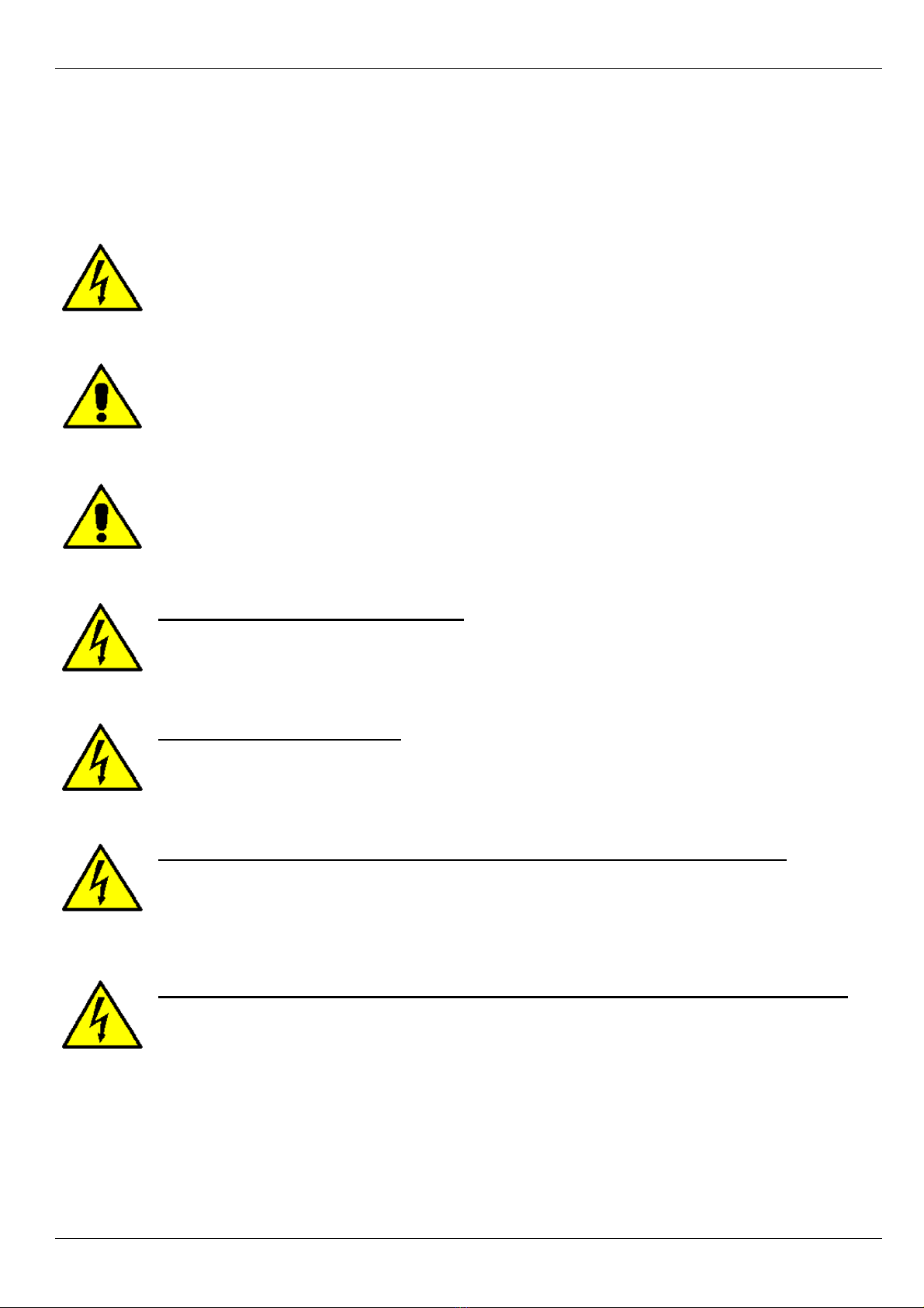
2.2 CD-KP 8
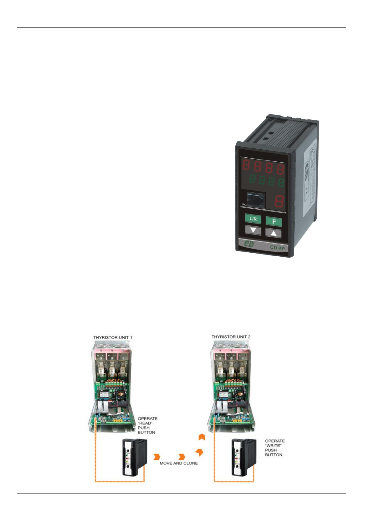
2.3 CD-EASY 8
2.4 Software Configurator 9
3 Quick Start ................................................................................................................ 10
4 MULTIDRIVE Sizing.................................................................................................... 11
5 Identification and Order Code.................................................................................... 12
5.1 Identification of the unit 12
5.2 Order Code 13
6 Installation ................................................................................................................ 14
6.1 Environmental installation conditions 14
6.2 Dimensions and Weight 15
6.3 Fixing holes 16
7 Wiring instructions .................................................................................................... 17
7.1 Removing the cover 17
7.2 Wiring details 17
7.3 Power Terminals 19
7.4 Command Terminals 20
7.5 Diagram of control connection 21
8 Power output features ............................................................................................... 22
8.1 Derating curve 22
8.2 Cooling fans 22
9 Led status and Alarms ............................................................................................... 23
9.1 LED Status Table 23
9.2 Critical Alarms 24
9.3 Not Critical Alarm 24
9.4 Calibration Procedure 25
10 Control Panel ........................................................................................................... 25
10.1 Scroll the parameters 26
10.2 Operator Menu 27