3
CONTENTS
1. FIRST START-UP...................................................................................................................................................................... 4
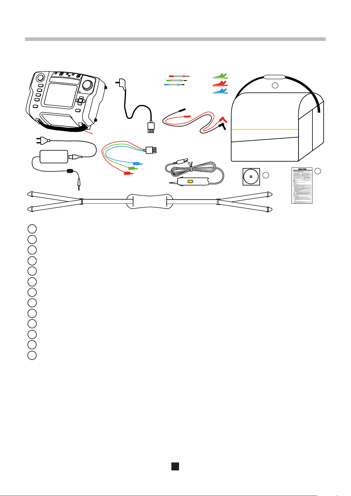
1.1. Unpacking ...................................................................................................................................................................... 4
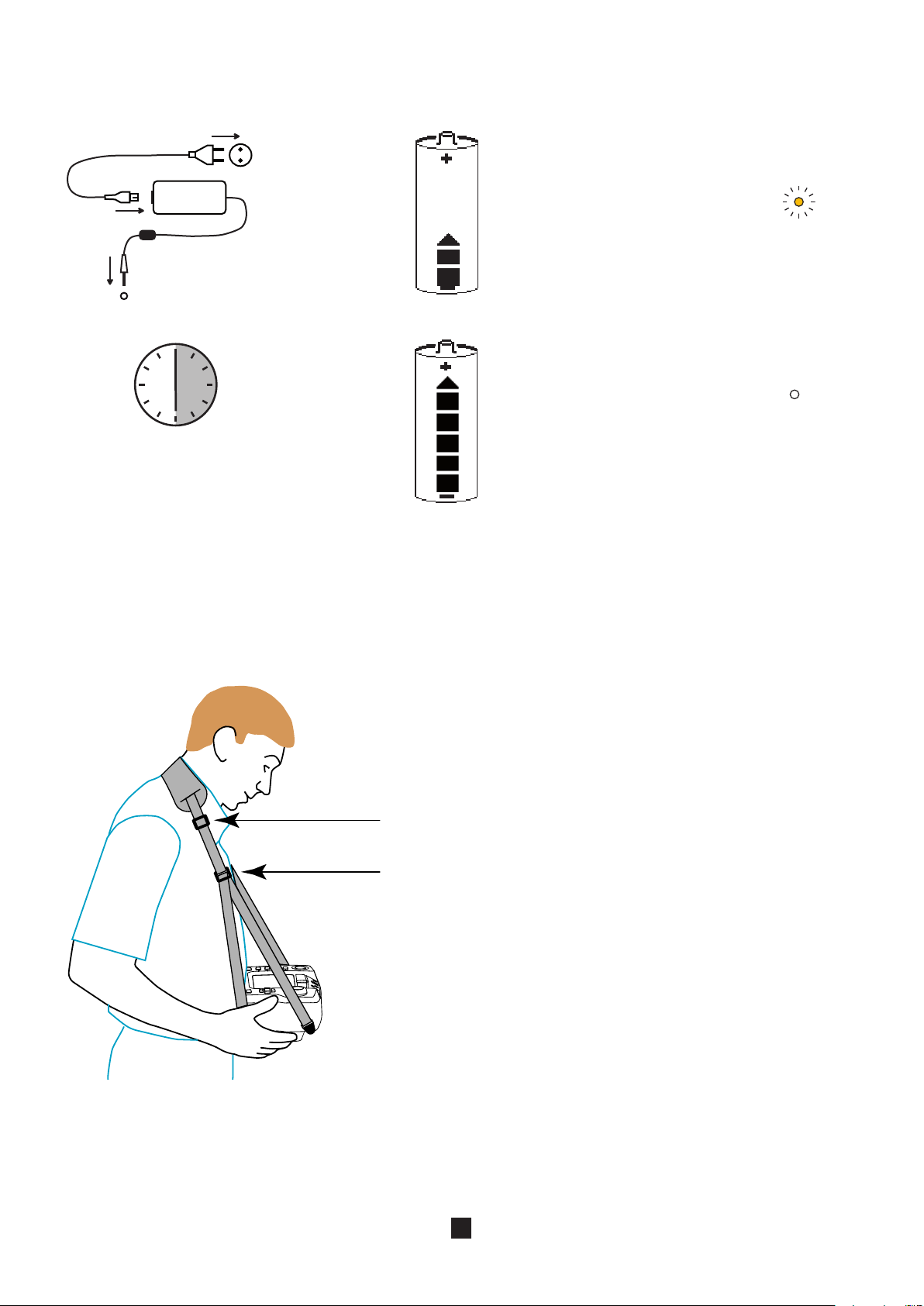
1.2. Charging the battery....................................................................................................................................................... 5
1.3. Carrying the device ........................................................................................................................................................ 5
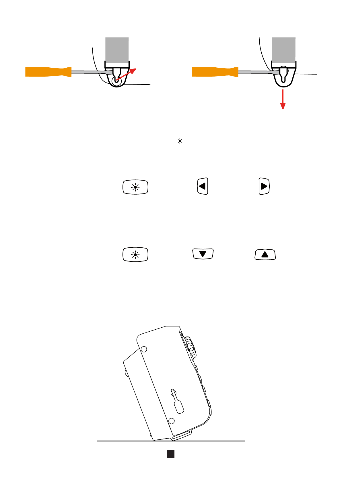
1.4. Contrast and brightness of the display .......................................................................................................................... 6
1.5. Use on a desktop ........................................................................................................................................................... 6
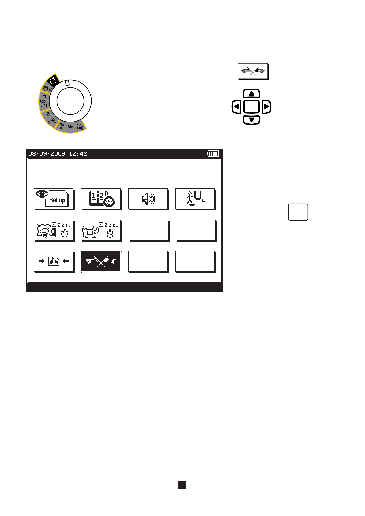
1.6. Choice of language ........................................................................................................................................................ 7
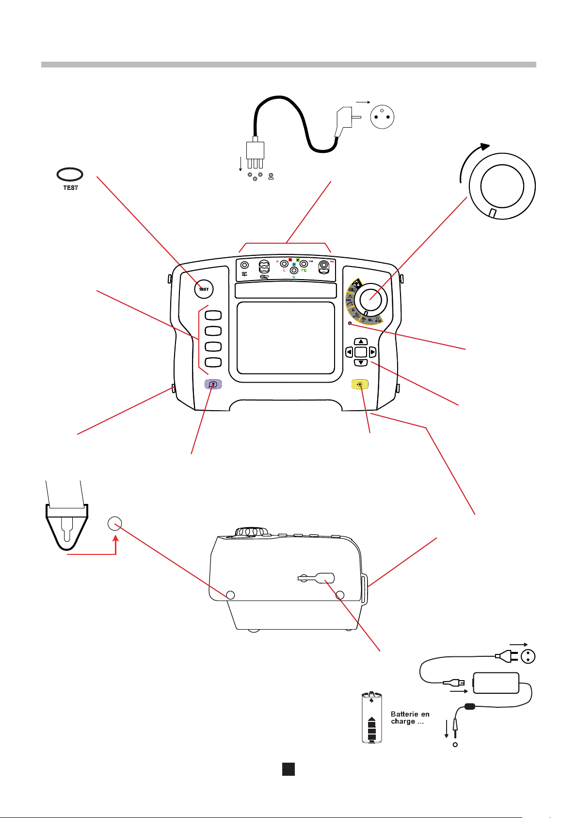
2. PRESENTATION OF THE DEVICE........................................................................................................................................... 8
2.1. Functions of the device ................................................................................................................................................. 9
2.2. Keypad ........................................................................................................................................................................... 9
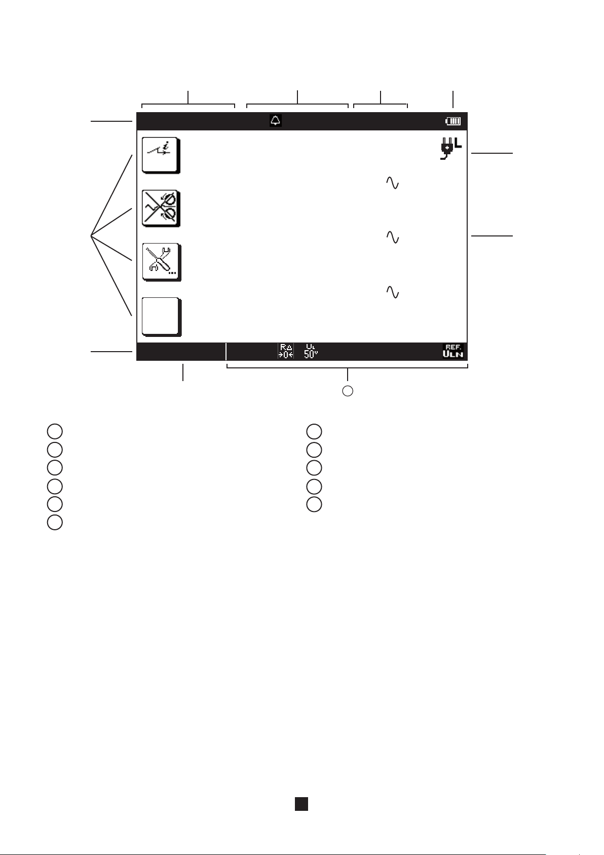
2.3. Display unit................................................................................................................................................................... 10
3. PROCEDURE ......................................................................................................................................................................... 11
3.1. General ......................................................................................................................................................................... 11
3.2. Voltage measurement................................................................................................................................................... 11
3.3. Resistance and continuity measurement ..................................................................................................................... 13
3.4. Insulation resistance measurement.............................................................................................................................. 17
3.5. 3P earth resistance measurement................................................................................................................................ 20
3.6. Loop impedance measurement (ZS)............................................................................................................................. 24
3.7. Measurement of the line impedance (Zi)....................................................................................................................... 27
3.8. Earth measurement on live circuit (Za, Ra).................................................................................................................... 30
3.9. Selective earth measurement on live circuit................................................................................................................. 35
3.10. Test of residual current device.................................................................................................................................... 38
3.11. Current and leakage current measurement................................................................................................................ 46
3.12. Direction of phase rotation ......................................................................................................................................... 48
3.13. Compensation for the resistance of the measurement leads..................................................................................... 50
3.14. Adjustment of the alarm threshold ............................................................................................................................. 52
4. ERROR INDICATION.............................................................................................................................................................. 53
4.1. No connection .............................................................................................................................................................. 54
4.2. Out of measurement range........................................................................................................................................... 54
4.3. Presence of dangerous voltage.................................................................................................................................... 54
4.4. Invalid measurement .................................................................................................................................................... 54
4.5. Device too hot .............................................................................................................................................................. 54
4.6. Check of internal protection devices............................................................................................................................ 55
5. SET-UP.................................................................................................................................................................................... 56
6. TECHNICAL CHARACTERISTICS ........................................................................................................................................ 59
6.1. General reference conditions ....................................................................................................................................... 59
6.2. Electrical characteristics............................................................................................................................................... 59
6.3. Variations in the range of use ....................................................................................................................................... 70
6.4. Intrinsic uncertainty and operating uncertainty............................................................................................................ 72
6.5. Power supply................................................................................................................................................................ 72
6.6. Environmental conditions............................................................................................................................................. 74
6.7. Mechanical characteristics .......................................................................................................................................... 74
6.8. Conformity to international standards.......................................................................................................................... 75
6.9. Electromagnetic compatibility (EMC) ........................................................................................................................... 75
7. DEFINITIONS OF SYMBOLS................................................................................................................................................. 76
8. MAINTENANCE...................................................................................................................................................................... 78
8.1. Cleaning ....................................................................................................................................................................... 78
8.2. Replacing the battery ................................................................................................................................................... 78
8.3. Resetting the device..................................................................................................................................................... 79
8.4. Metrological check ....................................................................................................................................................... 79
8.5. Repair ........................................................................................................................................................................... 79
9. WARRANTY ........................................................................................................................................................................... 80
10. TO ORDER............................................................................................................................................................................ 81
10.1. Accessories ................................................................................................................................................................ 81
10.2. Replacement parts ..................................................................................................................................................... 81