CHEMCHAMP A18 User manual
MODEL A18
SOLVENT RECOVERY SYSTEMS
(EXPLOSION PROOF UNITS)
FOR PROPER AND SAFE USE OF THIS CHEMCHAMP
EQUIPMENT, PLEASE FOLLOW THIS DOCUMENT AND LOCAL
AUTHORITY.
KEEP THIS DOCUMENT FOR FUTURE REFERENCE.
Revision: 122203

TE
CHNICAL DATA:
MODEL:
CHEMCHAMP A18
CLASSIFICATION:
CLASS 1, DIVISION 1,
GROUPS C, D, E, F, G
ELECTRICAL PROTECTION:
INTRINSIC PROTECTION &
EXPLOSION PROOF ENCLOSURES
FUSE PROTECTION:
30 AMP DELAYED ACTION
VOLTAGE:
240 VAC, SINGLE PHASE,
50 or 60 Hz
AMPERAGE:
20 AMP
POWER:
4.2 kW
CAPACITY:
18 US GALLONS (68.14 litres)
OPERATING TEMPERATURE:
53.6 to 379.4 FAHRENHEIT
(12° CELSIUS TO 193° CELSIUS)
SAFETY THERMOSTATS:
ELEMENT: 395 Fahrenheit
(ELEMENT: 202° CELSIUS)
MATERIAL (DIST
ILLATION CHAMBER):
STAINLESS STEEL
PATENT PENDING PROCESS:
1) VAPOR MANAGEMENT SYSTEM.
2) PROCESS CONTROL METHOD.
3) ANTI
-
PRESSURE SYSTEM.
4) DIRECT CONDENSATION METHOD.
DIMENSIONS:
LENGTH:
82 Inches (208 cm)
HEIGHT:
67 Inches (170 cm)
WIDTH:
30.5 I
nches (77.5 cm)
DISTILLATION TIME:
6
-
10 HOURS
COOL DOWN TIME:
9-
12 HOURS.

INTRODUCTION:
In dealing with liquid hazardous waste companies have had to pay a costly rate for pick-
up
and repurchase of new chemicals for their process. This recycler reduces these costs.
The means of accomplishing the above is through a process known as distillation. Each
group of chemicals has a vapor temperature, which we utilize to separate from
contaminants. This unit is explosion proof, which means it can be used for flammable and
non
-
flammable solvents ranging from acetone to water.
SAFETY FEATURES:
The unit comes equipped with the following patent pending safety features:
A)
Automated temperature and time setting. The unit will automatically set its own time
and temperature in accordance with the requirements of the particular solvent or
solvents poured into its distillation chamber for recycling. The result being the
operator only needs to pour the solvent in and press START .
B)
Oil immersion
element.
C)
Element control and safety probes.
D)
Oil maintenance timer and indicator. The unit will automatically indicate when oil
requires to be changed. If oil is not changed within a safe time period, the unit will
automatically shut down indicating the word OIL on its display panel until oil is
changed. This ensures proper and safe operation of the unit for years to come.
E)
Intrinsically safe controls.
F)
Self
-
cooling condensation drum.
G)
A superior vapor management system. The vapor management system limits VO
C
emissions during distillation, resulting in a safe healthy working environment with an
ultimate recovery of solvent.
H)
OFF button for manual shut off at any time. If the unit is in cycle and the stop
button is pressed the unit will shut off and automatically go into cool down mode
with yellow light flashing and digital displaying temperature until the unit reaches
134.6
Fahrenheit (57° Celsius). The yellow light and display will turn off and green
light will come on indicating unit is safe to open and re
-
start cycle.
I)
Automatic shut off when cycle is complete.
J)
Unit operates at zero pressure. Cover will release at 0,15 Bar (2 PSI).
L)
Temperature Probes check each other 256 times per second to ensure the other is
working within 50 degrees Fahrenheit (10 deg
rees Celsius) of itself.
M)
Temperature Probes are linked to an Analog circuit as well as the microprocessor.
In the event the processor malfunctions, the Analog circuit will turn the unit off at
395 degrees Fahrenheit (202 degrees Celsius) until the unit
cools.
N)
Fuse Protection.
O)
Overfill protection. Float sensor automatically shuts elements down in the event
that the collection drum becomes overfull and displays Er10 .

PLEASE NOTE THE FOLLOWING:
1.
This unit is designed to distill solvent with a boiling temperature less than 356 degrees
Fahrenheit (180 degrees Celsius).
2.
This unit should never be used to distill any chemical with an auto-ignition temperature
below 437 degrees Fahrenheit (225 degrees Celsius). Before initiating the distillatio
n
process always consult the appropriate chemical data sheet.
3.
The distilled solvent must be collected in the drum provided with unit, caution should be
taken that solvent not be accidentally spilled.
4.
If distilling water, system must be flushed of all solv
ents prior to operation.
5.
NITROCELLULOSE must
never
be distilled in this unit, as this may cause conditions of
danger.
6.
Residues must be disposed of in accordance to local laws.
7.
When cleaning residues from unit use only non
-
sparking tools.
8.
Opening cover befo
re allowed time will cause gasket swelling & dislocation.
9.
Operators should wear anti
-
static clothing.
10.
Operating staff must be fully educated on the safe and correct use of unit and
protection devises.
11.
Gasket of the lid is to be replaced every 2 years.
12.
Thi
s unit is not equipped with a plug, the proper connection must be implemented in
accordance with the local authority.
13.
Unit must be operated with the provided collection drum connected to the condensation
drum. (see figure 1)
FAILURE TO FOLLOW ANY OF THE ABOVE COULD CAUSE PERSONAL INJURY
AND PROPERTY DAMAGE.

INSTALLATION OF UNIT:
Figure 1
1.
LOCATION:
Caution- To reduce the risk of fire or explosion, install, operate, and
maintain this equipment in accordance with this instruction manual. This unit is for use
in 104oF (40oC) environment with no forced ventilation. Under these conditions, the
unit shall be spaced a minimum 3 feet (0.914m) from potential sources of ignition such
as electrical receptacles, switches, pilot lights, fixtures, contacts, and other similar
equipment that can produce sparks. If the equipment is used in higher ambient
temperatures, an increase in spacing to sources of ignition shall be considered. This
unit has only been investigated for use with solvent with a maximum ignition
temperature of 437
o
F (225
o
C).
This unit is designed for use in Class 1, Division 1. Note: This unit is not equipped
with a plug, the proper connection must be implemented in accordance with the local
authority.
2.
ELECTRICAL REQUIREMENTS:
The A18 unit is to be either plugged or wired into an
electrical source with 200
250 volts and on a 25 amp circuit.
3.
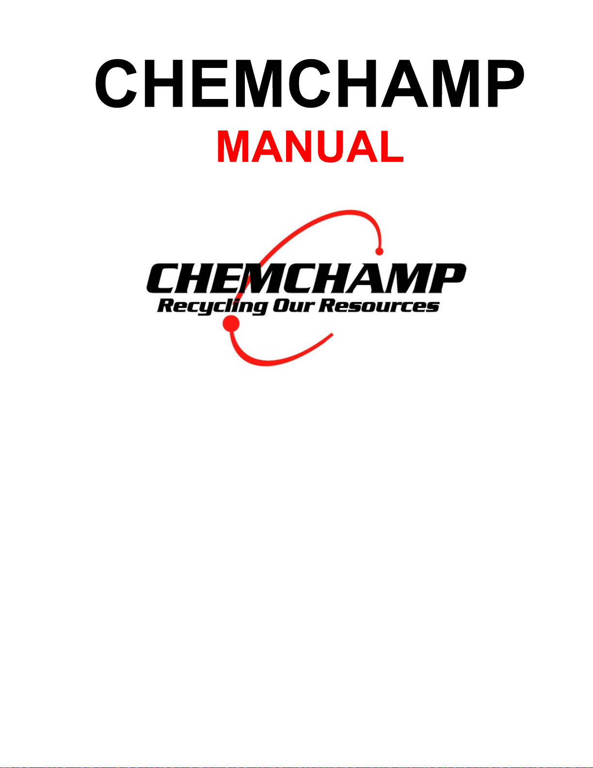
OIL AIR RELEASE VALVE: Open front door and replace oil cap marked with an X
with oil cap found in distillation chamber. The oil cap in distillation chamber has a hole
in center of cap.
4.
PREPARING THE CONDENSATION
DRUM:
The condensation drum acts as the main
means for condensing the distilled vapors. The condensation drum is shipped empty
and must be filled with the intended solvent (the solvent that will be distilled in the unit)
1.
Vent mount
2.
Lid clamp
3.
Lid
4.
Condenser column
5.
Front door
6.
Condensation drum
fill hole
7.
Condensation drum
8.
Collection drum
prior to operation. Remove the 2 plug from the condensation drum fill hole. Pour 36
gallons of intended solvent into hole using a funnel (not provided). Unit can be over
filled and then drained to the correct level by connecting the collection can and fully
draining any excess.
Be sure to empty collection can prior to operating unit.
5.
PREPARING CONDENSER COLUMN (MAGIC BOX) AND CONNECTING THE
VENT: The condenser column or magic box acts as a vent for the system and as a
secondary condensing module. The condenser column is shipped empty and must be
filled with tap water prior to operation. Rotate the column lid, pour water into container
until water level is 1 below top of container. Replace lid and attach vent hose to vent
mount on column (see figure 2). Attach other end of vent hose to a formidable vent
away from any source of ignition.
Figure 2
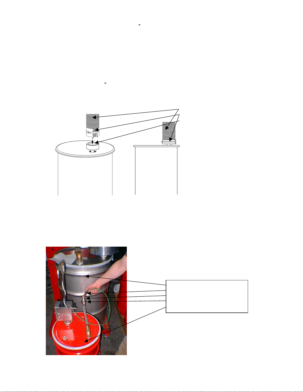
6.
ATTACHING COLLECTION DRUM: The collection vessel is a fully mobile unit
complete with its own pump and grounding attachment. The collection vessel must be
connected to the condensation drum via the solvent line quick-connect and the
grounding clamp attached to the condensation drum connector prior to each cycle (see
figure 3).
Figure 3
1.
Condensation drum
2.
Grounding attachment
3.
Condensation drum connector
4.
Solvent line quick connect
5.
Collection drum
VENT HOSE
VENT CLAMP
VENT MOUNT

7.
GET
TING READY: Connect power. Press START button and green light will come
on. The green light signifies the unit is ready to work and is safe to open.
INSTALLATION OF BAGS:
1.
Open cover.
2.
Remove bag holder.
3.
Open bag and place inside bag holder.
4.
Fold t
op of bag over the top ring of bag holder.
5.
Squeezing top ring, fit bag holder and bag into unit making sure bag is held open once
installed.
6.
Make sure bag is under the vapor manifold, and waste intake valve making sure they
are not blocked or covered (see figure 4).
Figure 4
7.
Pour solvent waste into receptacle bag. Maximum level is 1.5 Inches (3.8 cm) below
top of bag holder. The unit is designed for a maximum volume of 18 US Gallons (68.14
litres).
Over filling will result in overflow into vapo
r manifold resulting in dirty recycled solvent.
Over filling will also cause paint getting in behind the bag. This will make it difficult to
remove the bag, as the paint will act as glue making the bag stick to the bottom. If sticking
happens press START
and let unit warm up for 5 minutes. Press OFF and gently pull
bag out.
We recommend the use of CHEMCHAMP BAGS; other types of bags may deteriorate
during cycle and create a hard residue at the bottom of distillation chamber that will
be difficult to remove.
1.
Lid
2.
Distillation chamber
3.
Waste bag
4.
Bag
holder (behind
waste bag)

OPERATION OF UNIT:
1.
Connect power.
2.
Press START button and green light will come on. The green light signifies the
unit is ready to begin a new batch and is safe to open.
3.
Open lid.
4.
Remove bag holder.
5.
Place new waste
bag inside holder.
6.
Fold overlap of bag over the top of the holder.
7.
Place bag and holder inside distillation chamber.
8.
Pour a maximum of 18 US Gallons (68.14 litres) of waste solvent into bag, making
sure not to pour any liquid into outlet manifold or behind waste bag. The maximum
level is 1.5 Inches (3.8 cm) below the top of the bag holder
9.
Close lid and clamp the lid clamp down.
10.
Ensure collection drum is empty and properly connected to the condensation drum
(see figure 3).
11.
Press START , yellow light and digital display will come on. The display shows the
temperature of the thermal oil.
12.
Green light will stay on with yellow light until temperature of the thermic oil reaches
140 degrees Fahrenheit (60 degrees Celsius). At this point the green light will turn
off. Unit will automatically set temperature and time in accordance to the solvent or
solvents to be recycled.
13.
Once distillation is complete the unit will automatically shut off and the yellow light
will begin flashing indicating the unit is OFF and is cooling down. The yellow light
will flash until the unit has fully cooled. At this point the yellow light and the digital
display will turn OFF and the unit is ready for the next cycle. The green light will
come on once the unit is safe to open.
14.
Open cove
r and remove bag residue. Place residue bag into proper collection drum.
* Please note that by using bags in the distillation chamber, you eliminate the cleaning
process.
** Please use necessary safety precautions when following these steps.
*** Very Im
portant: Eye wear, boots, gloves and masks should be worn at all times.
****CAUTION: Unit surfaces will be hot when in use.
*****Cover should not be open unless green light is on.
******Waste bag should be changed between each cycle.
OIL MAINTENANCE:
OIL CHANGE
The unit will automatically indicate it requires an oil change by flashing the word OIL on
its display panel.
1.
Disconnect power.
2.
Open front door of unit.
3.
Remove top and middle oil cap.

4.
Place collection pan under Oil Drain.
5.
Remove bottom oil cap & drain.
Caution:
Make sure when emptying oil that the unit is
completely cooled
6.
Replace bottom oil cap.
7.
Hang a collection pail on middle oil nipple.
8.
Using a flexible funnel, refill oil with ChemChamp Heating Oil through top oil nipple. Fill
unit unt
il oil begins to drain from middle oil nipple.
9.
Allow excess to fully drain from middle oil nipple.
10.
Replace middle and top oil caps, NOTE: the top oil cap has a hole in it.
11.
Reconnect power.
12.
Press the START button for 20 seconds. All lights will come on and the screen will
display Clr and then 8888 , indicating self-diagnostic and reset of unit is complete.
13.
Disconnect power.
14.
Reconnect power and you are ready to set the unit for solvent or water mode.
OIL TOP
-
UP
1.
Disconnect power.
2.
Open front door of uni
t.
3.
Remove top and middle oil cap.
4.
Using a flexible funnel, refill oil with ChemChamp Heating Oil through top oil nipple. Fill
unit until oil begins to drain from middle oil nipple.
5.
Allow excess to fully drain from middle oil nipple.
6.
Replace middle and top
oil caps, NOTE: the top oil cap has a hole in it.
7.
Reconnect power.
COLLECTION DRUM:
The collection drum provided with unit is the only vessel to be used for collection of
distilled solvent. This drum holds a maximum of 18 US Gallons (68.14 litres). It is fully
mobile and has its own pump. The pump is pneumatically powered and is operated with a
push button. The unit must be connected to an air supply of at least 80 psi for the pump to
function properly. The collection drum comes equipped with a grou
nding clamp to connect
the unit to a suitable ground whenever stationary.
The collection drum must be empty and connected to the condensation drum via the
solvent line quick connect for the duration of a distillation cycle. The collection drum must
be
attached to a suitable ground during a cycle. The condensation drum connector is a
suitable ground.

TROUBLE SHOOTING:
Problem
Reason
Solution
Bag hard to pull out.
-
Dirty Inner Bucket.
- Turn machine on until
it reaches 131
degrees Fahrenheit
(55 degrees Celsius),
remove bag and
clean.
Machine will not
come on.
-
Surge in power.
-
Replace fuse or fuses
in explosion proof
box.
Dirty Distillate.
Rust colored solvent.
-
Dirty manifold.
-
Dirty collection drum.
-
Rusty drum.
-
Clean manifold.
-
Replace or clean
drum.
-
Replace collection
drum.
Gasket swelling and
dislocating.
-
Lid was opened
before unit finished its
cool down mode.
-
Replace gasket
immediately.
Control panel error
message.
-
System failure.
-
Take note of error
message number i.e.)
Er01.
-
See error cod
e
section on following
page.
-
Contact ChemChamp.
Waste residues are
becoming soupy
-
Unit low on oil
-
Top unit up with oil
- See OIL
MAINTENANCE
SECTION
Unit smells during
operation
-
Increased vapor
losses
-
Add water to
condensation column

ERROR MESSAGES
CODE
ERROR
Er01
Probe 1 fault (Invalid temperature values). Room temperature is less
than 50 Fahrenheit
Er02
Probe 2 value too different from probe 1.
Er03
Probe 1 value too different from probe 2.
Er04
Over temperature fault (Hardware overte
mp trip).
Er05
Over temperature fault (From A/D read).
Er10
Condensation drum is overfull. Either the collection drum is full and
needs to be emptied or the collection drum is not connected during
cycle.
Table of contents

