Chongqing Huansong HS700 Manual

FOREWORD
Brief introduction to maintenance handbook of
HS700/600/500ATV
The handbook is edited by Technical Center of Chongqing Huansong Industries
(Group) Co., Ltd., and is supplied to dealers and technicians as document of technique.
Mainly, the handbook gives methods to check, maintain and repair four wheel
all-terrain vehicles (ATV), and supplies some relevant technique and performance data.
Some techniques and method inside may be used to check, maintain and repair other
models of ATV, although it is mainly for HS700ATV.
Please read the handbook through and fully understand it; otherwise, any improper
repairing and amounting would bring you problems, and accident may occur in your use.
Proper use and maintenance can guarantee ATV being driven safely, reduce its
malfunction, and help the vehicle remain its best performance.
The standards, performances and specifications mentioned in interpretation are
based on the sample in design, and they are subject to changes according to the
product's improvement without prior notice.
Third version ,Apri1,2011
Published by Chongqing Huansong Industries (Group) Co., Ltd.
Chongqing Huansong Industries (Group) Co., Ltd holds the copy right.
No publishing and reprinting without permission.
PDF compression, OCR, web optimization using a watermarked evaluation copy of CVISION PDFCompressor
CONTENT
CHAPTER 1
GENERAL INFORMATION
GENERAL INFORMATION 1
WATNINGS, CAUTIONS AND NOTES 1
DESCRIPTION 2
IDENTIFICATION CODE 3
Frame No. 3
Engine No. 3
SAFETY 4
Handing gasoline safely 4
Cleaning parts 5
Warning labels 5
SERIAL NUMBERS 6
FASTENERS 6
Torque specifications 6
Self-locking fasteners 6
Washers 6
Cotter pins 7
Snap rings and E-clips 7
SHOP SUPPLIES 8
Lubricants and Fluids 8
Engine oils 8
Greases 8
Brake fluid 9
Coolant 9
Cleaners, Degreasers and solvents 9
Gasket sealant 10
Gasket remover 10
Thread locking compound 10
BASIC TOOLS 10
Screwdrivers 11
1
PDF compression, OCR, web optimization using a watermarked evaluation copy of CVISION PDFCompressor

Wrenches 12
Adjustable wrenches 12
Socket wrenches, ratchets and handles 13
Impact drivers 13
Allen wrenches 14
Torque wrenches 14
Torque adapters 14
Pliers 16
Snap ring pliers 16
Hammers 16
Ignition grounding tool 17
PRECISION MEASURING TOOLS 17
Feeler gauge 17
Calipers 18
Micrometers 18
Adjustment 19
Care 20
Metric micrometer 20
Standard inch micrometer 21
Telescoping and small bore gauges 22
Dial Indicator 22
Compression gauge 23
Multimeter 23
ELECTRICAL SYSTEM FUNDAMENTALS 23
Voltage 24
Resistance 24
Amperage 24
BASIC SERVICE METHODS 24
Removing frozen fasteners 26
Removing broken fasteners 26
Repairing damaged threads 26
Stud Removal/Installation 27
Removing hoses 27
Bearings 27
2
PDF compression, OCR, web optimization using a watermarked evaluation copy of CVISION PDFCompressor
Removal 28
Installation 29
Interference fit 29
Seal replacement 31
STORAGE 31
Storage area selection 31
Preparing the motorcycle for storage 32
Returning the ATV to service 32
TROVBLESHOOTING 32
ENGINE PRINCIPLES AND OPERATING REQUIREMENTS 33
STARTING THE ENGINE 34
Engine is cold 34
Engine is warm 34
Starting the engine after a fall or after the engine stalls 34
Flooded engine 34
Engine cold with air temperature 35
Engine cold with air temperature above 35°C (95° F) 35
Cold engine with air temperature below 10 °C(50° F) 35
Engine is hot 36
Starting the engine after a fall or after the engine stalls 36
Flooded engine 36
ENGINE WILL NOT START 37
Identifying the problem 37
Spark test 38
Starter does not turn over or turns over slowly 39
POOR ENGINE PERFORMANCE 39
Engine starts but stalls and is hard to restart 39
Engine backfires, cuts out or misfires during acceleration 39
Engine backfires on deceleration 40
Poor fuel mileage 40
Engine will not idle or idles roughly 40
Low engine power 41
Poor idle or low speed performance 42
Poor high speed performance 42
3
PDF compression, OCR, web optimization using a watermarked evaluation copy of CVISION PDFCompressor
FUEL SYSTEM 43
Rich mixture 43
Lean mixture 43
ENGINE 44
Engine smoke 44
Black smoke 44
Blue smoke 44
White smoke or steam 44
Low engine compression 44
High engine compression 45
Engine overheating (cooling system) 45
Engine overheating (engine) 45
Preignition 46
Detonation 46
Power loss 46
engine noises 46
ENGLNE LUBRICATION
HIGH OIL CONSUMPTION OR EXCESSIVE 47
Exhaust smoke 47
Low oil pressure 47
High oil pressure 48
No oil pressure 48
Oil level too low 48
Oil contamination 48
CYLINDER LEAK DOWN TEST 48
ELECTRICAL TESTING 51
Preliminary checks and precautions 51
Intermittent problems 52
Electrical component replacement 53
Test equipment 53
Ammeter 53
Self-powered test light 53
Ohmmeter 54
Jumper wire 54
4
PDF compression, OCR, web optimization using a watermarked evaluation copy of CVISION PDFCompressor

TEST PROCEDURES 55
Voltage test 55
Voltage drop test 55
Peak voltage test 56
Continuity test 56
Testing for a short with a self-powered test light or ohmmeter 57
Testing for a short with a test light or voltmeter 57
BRAKE SYSTEM 57
Soft or spongy brake lever or pedal 57
Brake drag 59
Hard brake lever or pedal operation 59
Brake Grabs 59
Brake squeal or chatter 60
Leaking brake caliper 60
Leaking master cylinder 60
CHAPTER 2
SPECIFICATIONS
HOW TO USE CONVERSION TABLE OF UNIT 61
How to use conversion table 61
Definition of unit 61
GEBERAR SPECIFICATIONS 62
ENGINE SPECIFICATIONS 65
CHASSIS SPECIFICATIONS 71
ELECTRICAL SPECIFICATIONS 72
TIGHTENING TORQUES 75
Engine tightening torques 75
Chassis tightening torques 78
GENERAL TIGHTENING TORQUE SPECIFICATIONS 81
LUBRICATION PIONTS AND LUBRICANT TYPES 82
Engine 82
Chassis 83
HYDROGRAPHIC CHART 84
5
PDF compression, OCR, web optimization using a watermarked evaluation copy of CVISION PDFCompressor
LUBRICATION OIL WAY 85
CHAPTER 3
MAINTENCE AND ADJUSTMENT OF THE ATV
MAINTENANCE SCHEDULE 86
ENGINEAdjusting the valve clearance 88
Idle adjustment 90
Adjusting the throttle cable 91
Adjusting the starter cable 92
Checking the spark plug 93
Checking the ignition timing 93
Measuring the compression pressure 95
Checking the engine oil level 96
Changing the engine oil 97
CHASSIS
Cleaning the air filter 100
Checking the coolant level 101
Changing the coolant 102
Checking the coolant temperature warning light 105
Checking the v-belt 106
Cleaning the spark arrester 107
Adjusting the brake pedal 108
Checking the brake fluid level 109
Checking the front brake pads 110
Checking the rear brake pads 110
Checking the brake hoses and brake pipes 111
Bleeding the hydraulic brake system 111
Adjusting the select lever shift rod 113
Adjusting the brake light switch 113
Checking the final gear oil level 114
Changing the final gear oil 114
Checking the differential gear oil 115
6
PDF compression, OCR, web optimization using a watermarked evaluation copy of CVISION PDFCompressor
Changing the differential gear oil 115
Checking the constant velocity joint dust boots 116
Checking the steering system 117
Adjusting the toe-in 117
Adjusting the front shock absorbers 119
Adjusting the rear shock absorbers 119
Checking the tires 120
Checking the wheels 121
Checking and lubricating the cables 122
ELECTRICAL
Checking and charging the battery 123
Adjusting the headlight beam 129
Changing the headlight bulb 129
Changing the tail/brake light bulb 130
CHAPTER 4
ENGINE
ENGINE NOTE 132
ENGINE REMOVAL 133
CYLINDER HEAD AND CYLINDER HEAD COVER 135
ROCKER ARMS AND CAMSHAFT 140
VALVES AND VALVE SPRINGS 146
CYLINDER AND PISTON 152
ENGINE COOLING FAN AND A.C. MAGNETO 156
BALANCER GEARS AND OIL PUMP GEARS 160
PRIMARY AND SECONDARY SHEAVES
Primary and secondary sheaves 163
Primary sheave 164
Secondary sheave 165
CLUTCH 170
CRANKCASE
Starter motorand oil filter 174
Crankcase 175
7
PDF compression, OCR, web optimization using a watermarked evaluation copy of CVISION PDFCompressor

Crankcase bearings 176
CRANKSHAFT AND OIL PUMP
Crankshaft and oil pump 181
Oil pump 182
TRANSMISSION
Transmission 184
Drive axle assembly 185
MIDDLE GEAR
Middle drive shaft 189
Middle driven shaft 190
CARBURETOR 194
CHAPTER 5
CHASSIS
MALFUNCTION INSPECTION 199
STEERING OPERATION SYSTEM 202
The structure of the steering 202
The steering handle and cable 204
The handle switch and lever 207
Diassembling the parts of steering bar 209
Diassembling the parts of steering column 209
Checking and the steering operation system 211
Installing the steering operation system 212
Installing the steering handle 215
BRAKE SYSTEM 216
Preparation for checking before the maintenance of the brake system 216
Disk brake components 217
Front disk brake fuel pump 219
Front brake caliper 221
Checking the front brake disc 223
Replacing the front brake pads 224
Disassembling the front brakecalipers 226
Assembling the front brake calipers 227
8
PDF compression, OCR, web optimization using a watermarked evaluation copy of CVISION PDFCompressor
Installing the front brake calipers 227
Rear master cylinder 229
Rear brake caliper 233
Checking the rear brake disc 235
Replacing the rear brake pads 236
Disassembling the rear brake caliper 237
Assembling the rear brake caliper 238
Installing the rear brake caliper 239
Checking the master cylinder 240
Assembling the brake master cylinder 240
Installing the brake master cylinder 241
FOOTREST ASSEMBLY 242
WHEEL AND TYRE PARTS 244
Front wheels 244
Rear wheels 245
Front and rear wheel rim 246
Checking the wheel tyre 247
Checking the wheel hub 247
Installing the wheel hub 248
Installing the wheel tyre 248
Specification of wheel and tyre 249
TRANSMISSION SYSTEM 250
Front bridge 250
Disassembling the universal joint 255
Removing the differential gear assembly 255
Checking the joints 256
Checking the differential gear 256
Checking the gear motor 257
Assembling the universal joint 258
Adjusting the differential gear lash 258
Assembling the differential gear 259
Rear bridge 260
REVERSE MECHANISM PARTS 266
Adjusting reverse mechanism parts 268
9
PDF compression, OCR, web optimization using a watermarked evaluation copy of CVISION PDFCompressor

Checking and service of reverse mechanism 269
SUSPENSION 270
Front Suspension and arm 270
Disassembling, service and assembly the supporting rocker parts 273
Checking the front arms 274
Checking the front shock absorber 274
Installing the front arms and front shock absorber 275
Rear suspension 276
Rear arm shaft 277
Checking and service of rear suspension 279
Checking the stabilizer 280
Checking the rear arms 280
Checking the rear shock absorber 280
Installing the rear arms and rear shock absorber 281
COOLING SYSTEM 282
Radiator 282
Checking the radiator 284
Installing the radiator 285
Water pump 286
Disassembling the water pump 288
Checking the water pump 289
Assembling the water pump 290
SEAT 291
Dissassembling the seat 292
FUEL TANK 293
Fuel tnak cover parts 293
Fuel tnak parts 295
CHAPTER 6
ELECTRICAL COMPONENTS
ELECTRICAL SYSTEM MALFUNCTION INSPECTION 298
ELECTRICAL 299
ELECTRICALCOMPONENTS 299
-10-
PDF compression, OCR, web optimization using a watermarked evaluation copy of CVISION PDFCompressor
CHECKING THE SWITCH
Checking the switch 301
Checking the switch continuity 302
CHECKING THE BULBS AND BULB SOCKETS 303
IGNITION SYSTEM 304
CIRCUIT DIAGRAM 304
TROUBLESHOOTING 305
ELECTRIC STARTING SYSTEM 309
CIRCUIT DIAGRAM 309
TROUBLESHOOTING 310
STARTER MOTOR 312
Checking the starter motor 313
Assembling the starter motor 314
CHARGING SYSTEM 315
CIRCUIT DIAGRAM 315
TROUBLESHOOTING 316
LIGHTING SYSTEM 318
CIRCUIT DIAGRAM 318
TROUBLESHOOTING 319
CHECKING THE LIGHTING SYSTEM 320
If the headlights fail to come on 320
If the taillights fail to come on 321
SIGNALING SYSTEM 322
CIRCUIT DIAGRAM 322
TROUBLESHOOTING 323
CHECKING THE SIGNAL SYSTEM 324
If the brake lights fail to come on 324
If the neutral lights fail to come on 325
If the parking brake indicator light fails to come on 326
If the reverse indicator light fails to come on 327
If the coolant temperature warning 328
If the differential gear lock indicator light fails to come on 330
If the four-wheel drive indicator light fails to come on 332
COOLING SYSTEM 334
PDF compression, OCR, web optimization using a watermarked evaluation copy of CVISION PDFCompressor
Circuit diagram 334
Troubleshooting 335
2WD/4WD SELECTING SYSTEM 338
Circuit diagram 338
Troubleshooting 339
CHAPTER 7
ENGINE MANAGEMENT SYSTEM
INTRODUCTION
Ems (engine management system) 343
Typical components of EMS 343
Layout of EMS components 344
COMPONENTS OF EMS
Electronic control unit 345
Multec 3.5 injectors 346
Throttle body assembly(with stepper motor) 350
Engine coolant temperature sensor 352
Intake air pressure and temperature sensor 353
Oxygen sensor 353
Ignition coil 353
Fuel pump module 357
EMS FAULT DIAGNOSIS
EME fault diagnosis 363
Fault code list 363
CHAPTER 8
TROUBLESHOOTING
STARTING FAILURE/HARD STARTING 365
Fuel system 365
Electrical system 365
Compression system 366
POOR IDLE SPEED PERFORMANCE 367
-12-
PDF compression, OCR, web optimization using a watermarked evaluation copy of CVISION PDFCompressor

Poor idle speed performance 367
POOR MEDIUM AND HIGH-SPEED PERFORMANCE 367
Poor medium and high-speed performance 367
FAULTY GEAR SHIFTING 367
Shift lever does not move 367
Jumps out of gear 368
OVERHEATING 368
Overheating 368
FAULTY BRAKE 368
Poor braking effect 369
SHOCK ABSORBER MALFUNCTION 369
Malfunction 369
UNSTABLE HANDLING 369
Unstable handling 369
LIGHTING SYSTEM 370
Head light is out of work 370
Bulb burnt out 370
CHAPTER 9
HS600ATV SERVICE MANUAL
HS600ATV SUPPLEMENTARY 371
SPECIFICATIONS 372
Geberar specifications 372
Engine specifications 372
CHAPTER 10
HS500ATV SERVICE MANUAL
HS500ATV SUPPLEMENTARY 374
SPECIFICATIONS 375
Geberar specifications 375
Engine specifications 375
HS700ATV/HS600ATV/HS500ATV WIRING DIAGRAM 380
-13-
PDF compression, OCR, web optimization using a watermarked evaluation copy of CVISION PDFCompressor

WARNING:
GENERAL INFORMATION
GENERAL INFORMATION
The text provides complete information on maintenance, tune-up repair and overhaul, Hundreds
of photographs and illustrations created during the complete disassembly of four wheel all-terrain
vehicles (ATV) guide the reader through every job, All procedures are in step-by-step format and
designed for the reader who may be working on the ATV for the first time.
WARNINGS, CAUTIONS AND NOTES
The terms WARNING, CAUTION and NOTE have specific meaning in this manual.
emphasizes areas where injury or even death could result from negligence.
Mechanical damage may also occur. WARNINGS are to be taken seriously
CAUTION: emphasizes areas where equipment damage could result. Disregarding a
CAUTION could cause permanent mechanical damage. though injury is
unlikely.
provides additional information to make a step or procedure easier or clearer.
Disregarding a NOTE could cause inconvenience. but would not cause
equipment damage or injury.
NOTE:
1
PDF compression, OCR, web optimization using a watermarked evaluation copy of CVISION PDFCompressor
GENERAL INFORMATION
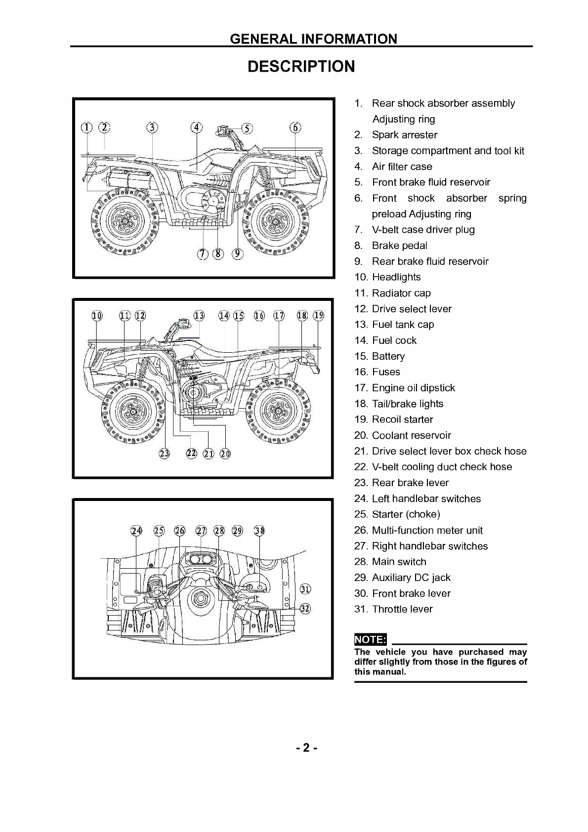
DESCRIPTION
2
1. Rear shock absorber assembly
Adjusting ring
2. Spark arrester
3. Storage compartment and tool kit
4. Air filter case
5. Front brake fluid reservoir
6. Front shock absorber spring
preload Adjusting ring
7. V-belt case driver plug
8. Brake pedal
9. Rear brake fluid reservoir
10. Headlights
11. Radiator cap
12. Drive select lever
13. Fuel tank cap
14. Fuel cock
15. Battery
16. Fuses
17. Engine oil dipstick
18. Tail/brake lights
19. Recoil starter
20. Coolant reservoir
21. Drive select lever box check hose
22. V-belt cooling duct check hose
23. Rear brake lever
24. Left handlebar switches
25. Starter (choke)
26. Multi-function meter unit
27. Right handlebar switches
28. Main switch
29. Auxiliary DC jack
30. Front brake lever
31. Throttle lever
NOTE:
The vehicle you have purchased may
differ slightly from those in the figures of
this manual.
PDF compression, OCR, web optimization using a watermarked evaluation copy of CVISION PDFCompressor

GENERAL INFORMATION
SAFETY
Professional mechanics can work for years and never sustain a serous injury or mishap. Follow
these guidelines and practice common sense to safely service the utility terrain venires
1. Do not operate the utility terrain venires in an enclosed area venires The exhaust gasses
contain carbon monoxide. an odorless, colorless and tasteless poisonous gas. Carbon
monoxide levels build quickly in small enclosed areas and can cause unconsciousness and
death in a short time. Make sure to properly ventilate the work area or operate the ATV side
2. Never use gasoline or any extremely flammable liquid to clean parts. Refer to cleaning parts
and handling Gasoline Safely in this section
3. Never smoke or use a torch in the vicinity of flammable liquids, such as gasoline or cleaning
solvent.
4. If welding or brazing on the ATV the fuel tank to a safe distance at least 50ft.(15m) away.
5. Use the correct type and size of tools to avoid damaging fasteners.
6. Keep tools clean and in good condition. Replace or repair worn or damaged equipment.
7. When loosening a tight fastener, be guided by what would happen if the tool slips.
8. When replacing fasteners, make sure the new fasteners are the same size and strength as the
original ones.
9. Keep the work area clean and organized.
10. Wear eye protection anytime the safety of the eyes is in question. This includes procedures that
involve drilling, grinding, hammering, compressed air and chemicals.
11. Wear the correct clothing for the job. Tie up or cover long hair so it does not get caught in
moving equipment.
12. Do not carry sharp tools in clothing pockets.
13. Always have an approved fire extinguisher available. Make sure it is rated for gasoline (Class B)
and electrical (Class C) fires.
14. Do not use compressed air to clean clothes, the ATV or the work area. Debris may be blown
into the eyes or skin. Never direct compressed air at anyone. Do not allow children to use or
play with any compressed air equipment.
15. When using compressed air to dry rotating parts, hold the part so it does not rotate. Do not allow
the force of the air to spin the part. The air jet is capable of rotating parts at extreme speed. The
part may disintegrate of become damaged, causing serious injury.
16. Do not inhale the dust created by brake pad and clutch wear. These particles may contain
asbestos. In addition, some types of insulating materials and gaskets may contain asbestos.
Inhaling asbestos particles is hazardous to one's health.
17. Never work on the ATV while someone is working under it.
Handling Gasoline Safely
Gasoline is a volatile flammable liquid and is one of the most dangerous items in the shop.
Because gasoline is used so often, many people forget it is hazardous. Only use gasoline as fuel
for gasoline internal combustion engines. Keep in mind when working on the machine, gasoline is
always present in the fuel tank, fuel line and carburetor. To avoid a disastrous accident when
4
PDF compression, OCR, web optimization using a watermarked evaluation copy of CVISION PDFCompressor
GENERAL INFORMATION
working around the fuel system, carefully observe the following precautions:
1. Never use gasoline to clean parts. Refer to Cleaning Parts in this section.
2. When working of the fuel system, work outside or in a well-ventilated area.
3. Do not add fuel to the fuel tank or service the fuel system while the ATV is near open flames,
sparks or where someone is smoking .Gasoline vapor is heavier than air, it collects in low areas
and is more easily ignited than liquid gasoline.
4. Allow the engine to cool completely before working on any fuel system component.
5. Do not store gasoline in glass containers. If the glass breaks, a serious explosion of fire may
occur.
6. Immediately wipe up spilled gasoline with rags. Store the rags in a metal container with a lid until
they can be properly disposed of, or place them outside in a safe place for the fuel to evaporate.
7. Do not pour water onto a gasoline fire. Water spreads the fire and makes it more difficult to put
out. Use a class B, BC or ABC fire extinguisher to extinguish the fire.
8. Always turn off the engine before refueling. Do not spill fuel onto the engine or exhaust system.
Do not overfill the fuel tank. Leave an air space at the top of the tank to allow room for the fuel to
expand due to temperature fluctuations.
Cleaning Parts
Cleaning parts is one of the more tedious and difficult service jobs performed in the home garage.
Many types of chemical cleaners and solvents are available for shop use. Most are poisonous and
extremely flammable. To prevent chemical exposure, vapor buildup, fire and serious injury, observe
each product warning label and note the following:
1. Read and observe the entire product label before using any chemical. Always know what type of
chemical is being used and whether it is poisonous and/or flammable.
2. Do not use more than one type of cleaning solvent at a time. If mixing chemicals is required,
measure the proper amounts according to the manufacturer.
3. Work in a well-ventilated area.
4. Wear chemical-resistant gloves.
5. Wear safety glasses.
6. Wear a vapor respirator if the instructions call for it.
7. Wash hands and arms thoroughly after cleaning parts.
8. Keep chemical products away from children and pets.
9. Thoroughly clean all oil, grease and cleaner residue from any part that must be heated.
10. Use a nylon brush when cleaning parts. Metal brushes may cause a spark.
11. When using a parts washer, only use the solvent recommended by the manufacturer. Make sure
the parts washer is equipped with a metal lid that will lower in case of fire.
Warning Labels
Most manufacturers attach information and warning labels to the ATV. These labels contain
instructions that are important to personal safety when operating, servicing, transporting and storing
the ATV. Refer to the owner's manual for the description and location of labels. Order replacement
5
PDF compression, OCR, web optimization using a watermarked evaluation copy of CVISION PDFCompressor

WARNING
GENERAL INFORMATION
labels from the manufacturer if they are missing or damaged.
SERIAL NUMBERS
Serial and identification numbers are stamped on various locations on the frame, engine and
carburetor body. Record these numbers in the Quick Reference Data section in the front of the
manual. Have these numbers available when ordering parts.
FASTENERS
Proper fastener selection and installation is important to ensure the motorcycle operates as
designed and can be serviced efficiently. The choice of original equipment fasteners is not arrived at
by chance. Make sure replacement fasteners meet all the same requirements as the originals
Many screws. Bolts and studs are combined with nuts to secure particular components. to
indicate the size of a nut. Manufactures specify the internal diameter and the thread pitch
The measurement across two flats on a nut or bolt indicates the wrench size
Do not install fasteners with astrength
classification lower than what was originally
installed by the manufacturer doing so may
cause equipment failure and or damage
Torque Specifications
The material used in the manufacturing of the ATV may be subjected to uneven stresses if the
fasteners of the various subassemblies are not installed and tightened correctly. Fasteners that are
improperly installed or work loose can cause extensive damage. it is essential to use an accurate
torque wrench as described in this chapter
Self-Locking Fasteners
Several types of bolts. Screws and nuts incorporate a system that creates interference between
the two fasteners. Interference is achieved in various ways. The most common types are the nylon
insert nut and a dry adhesive coating on the threads of a blot.
Self-locking fasteners offer greater holding strength than standard fasteners, which improves
their resistance to vibration. All self-locking fasteners cannot be reused. The materials used to from
the lock become distorted after the initial installation and removal. Discard and replace self-locking
fasteners after removing them. Do not replace self-locking fasteners with standard fasteners.
Washers
The two basic types of washers are flat washers and lock washers. Flat washers are simple discs
6
PDF compression, OCR, web optimization using a watermarked evaluation copy of CVISION PDFCompressor
This manual suits for next models
5
Table of contents
Other Chongqing Huansong Offroad Vehicle manuals


 owner's manual")


