Clean Energy CE-140 User manual

OWNER’S MANUAL
CE-140 Mul-Oil Furnace
CE-180 Mul-Oil Furnace
CE-250 Mul-Oil Furnace
With CE-3 Burner
CE-330 Mul-Oil Furnace
With CE-4 Burner
Clean Energy Heating Systems, LLC
540 Maple Street, Honey Brook, PA 19344
www.CleanEnergyHeatingSystems.com
(888) 519-2347
WARNING: For your safety - DO NOT store gasoline or other flammable
vapors and liquids in the vicinity of this or any appliance.

8/22/12 Part # 70001

TABLE OF CONTENTS
SAFETY CONSIDERATIONS AND GUIDELINES..............................................................4
FURNACE ASSEMBLY....................................................................................................... 6
(1) Installing the blower........................................................................................... 7
(2) Air discharge configuration................................................................................ 9
- Unit Heater (Free Air with no ductwork)
- Central Furnace (ductwork installed)
(3) Installing the combustion chamber target..........................................................12
(4) Installing the burner........................................................................................... 13
(5) Installing the connector block and oil line.......................................................... 14
FURNACE INSTALLATION................................................................................................ 15
(1) Selecting a location........................................................................................... 16
(2) Mounting the furnace in position........................................................................17
(3) Connecting the electrical supply........................................................................ 18
(4) Installing the chimney components................................................................... 19
(5) Oil storage tank set up ......................................................................................21
(6) Installing the metering pump and oil lines......................................................... 21
(7) Connecting the compressed air line.................................................................. 26
(8) Installing the wall thermostat............................................................................. 27
PREPARING THE METERING PUMP FOR START UP.....................................................27
STARTING AND ADJUSTING THE BURNER.................................................................... 28
(1) Preparing the burner for start up....................................................................... 28
(2) Priming the oil pump..........................................................................................28
(3) Adjusting the Burner.......................................................................................... 28
RESETTING THE OIL PRIMARY CONTROL.....................................................................29
SETTING THE DRAFT........................................................................................................30
MAINTENANCE..................................................................................................................31
FURNACE DIMENSIONS...................................................................................................35
WIRE DIAGRAMS.............................................................................................................. 37
PARTS DIAGRAMS............................................................................................................ 42
SERVICE RECORDS......................................................................................................... 66
WARRANTY INFORMATION............................................................................................. 67

WARNING: Incorrect installation, adjustment, or misuse of this heating equipment
could result in death, severe personal injury, or substantial property damage.
To the Equipment Owner:
• Read and understand all instructions
provided in this manual
• Installation and service must be
completed by qualified personnel who
are familiar with oil-fired appliances.
• Save this manual for future reference.
To the Professional, Qualified Installer or
Service Agency:
• Read and carefully follow all instructions
provided in this manual before installing, starting,
or servicing this heating equipment.
• All installations must be made in accordance
with state and local codes having jurisdiction.
SAFETY CONSIDERATIONS AND GUIDELINES
NOTICE: Intended to clarify or bring special attention to previous information.
CAUTION: Indicates a hazardous situation, which can result in minor or moderate
personal injury if not avoided.
WARNING: Indicates a hazardous situation, which can result in death or serious
personal injury if not avoided.
DANGER: Indicates a hazardous situation, which will result in death or serious
personal injury if not avoided.
DANGER: DO NOT store or use gasoline or other flammable/explosive liquids/vapors
in or around the furnace.
DANGER: DO NOT operate the furnace if excess oil, oil vapors, or fumes have
accumulated in or around the furnace.
DANGER: Improper installation, operation, or maintenance of the furnace may create
a fire or explosion hazard.
WARNING: DO NOT mix unapproved substances to the used oil supply, such as:
• Anti-Freeze
• Carburetor Cleaner
• Paint Thinner
• Parts Washer and/or Solvents
• Gasoline
• Oil Additives
• Chlorinated solvents
• Any other inappropriate / hazardous material
Instruct your personnel NEVER to add unapproved substances to your used oil.
Burning any unapproved substance will immediately void the furnace warranty and
may cause damage and unsafe operating conditions.
WARNING: Unauthorized furnace modifications may cause damage and unsafe
operating conditions.
HAZARD DEFINITIONS:
SAFETY CONSIDERATIONS:
4

WARNING: The CE-3 Burner is only approved for use on a furnace manufactured by
Clean Energy Heating Systems. The Furnace is only approved for use with the CE-3
burner manufactured by Clean Energy Heating Systems.
WARNING: The installation, operation, and maintenance of this equipment in the
United States must be done by qualified personnel according to instructions in the
Clean Energy Heating Systems Owner’s Manual and in accordance with all national,
state, and local codes or authorities having jurisdiction and the following standards:
NFPA 30 Flammable and Combustible Liquids Code
NFPA 30A Automotive and Marine Service Station Code
NFPA 31 Installation of Oil Burning Equipment
NFPA 70 National Electrical Code
NFPA 88A Parking Structures
NFPA 88B Repair Garages
NFPA 211 Chimney’s, Fireplaces, Vents and Solid Fuel Burning Appliances
Likewise, the installation, operation, and maintenance of this equipment in Canada must
be done by qualified personnel according to instructions in the Clean Energy Heating
Systems Owner’s Manual and in accordance with all regulations and authorities having
jurisdiction and the following CSA Standards:
B139 Oil Burning Equipment
B140 General Requirements for Oil Burning Equipment
C22.1 Canadian Electrical Code, Part 1
GUIDELINES FOR FURNACE USE:
• This furnace is for industrial and/or commercial use only. This furnace is not intended
for residential use.
• This furnace is safety listed to burn the following fuels:
• #2 fuel oil
• Used crankcase oil up to 50 SAE
• Used hydraulic oil
• Used automatic transmission fluid (U.S.)
• The EPA regulations for burning used oil are as follows:
• Your supply of used oil is generated on-site. You may also collect oil from
“do-it-yourself” oil changers.
• Do not mix hazardous wastes, such as chlorinated solvents, with your used oil.
• The exhaust gases of the furnace must be vented to the outside with an
appropriate stack system.
• The furnace is used to recycle used oil for “heat recovery”. The furnace is not
to be used in warm weather just to dispose of used oil.
• Only trained authorized personnel should service and maintain the furnace. Be sure
the furnace receives annual maintenance to ensure safe and efficient operation.
5
SAFETY CONSIDERATIONS AND GUIDELINES

GUIDELINES FOR USED OIL TANKS:
(1) The tank installation must comply with NFPA 30 and NFPA 31 fire codes.
(2) The tank should be installed on a slight slope with a drain on the low end to allow sludge
and water to be removed from the bottom of the tank.
(3) All oil lines must be constructed of copper, steel, or brass components. DO NOT use
rubber, plastic, or any other inappropriate material for oil lines.
(4) Be sure to follow all instructions for tank installation in the Owner’s Manual.
6
Figure 1: Typical Furnace Assembly
WARNING: To avoid serious injury or death, only store the following substances in
the oil supply tank:
(1) Used Crankcase Oil
(2) Used Automatic Transmission Fluid (ATF)
(3) Used Hydraulic Oil
(4) #2 Fuel Oil (Diesel Fuel)
DO NOT put flammable or corrosive substances such as gasoline, chlorinated solvents,
paint thinner, or any other unsafe substance in the oil supply tank.
WARNING: To avoid serious injury or death, do not weld or allow open flames within
35 feet of the used oil supply tank.
Follow the steps below for furnace assembly (refer to Figure 1):
(1) Install the blower
(2) Determine the appropriate air discharge configuration
- Unit Heater (Free Air with no ductwork)
- Central Furnace (ductwork installed)
(3) Install the combustion chamber target
(4) Install the burner
(5) Install the connector block and oil line
FURNACE ASSEMBLY
SAFETY CONSIDERATIONS AND GUIDELINES
CE70012
1
3
2
5
4

7
Installing the Blower (CE-140, CE-180, and CE-250):
(1) Refer to Figure 2.
(2) Place the blower inside the mounting angles on the back of the furnace with the blower
bubble turned up.
(3) Use the included #10 self-drilling screws to secure the blower housing to the mounting
angle brackets on the back of the furnace cabinet.
(4) Connect the flexible conduit from the blower motor to the rear electrical box.
(5) Connect the wire leads according to the electrical schematic label in the rear junction box.
(6) Fasten the blower guards with the remaining #10 self-drilling screws to each side of the
blower.
WARNING: Blower guards must be in place to prevent personal injury. NEVER
operate the furnace without all guards in place!
NOTICE: The blower motor is designed to operate with the guards in place. Without the
guards in place the blower will move more air which may overload and damage the blower
motor.
NOTICE: The blower must be mounted with the “bubble” turned up. If the blower is not
mounted in this position, the internal air flow through the furnace cabinet will change which
may cause the unit to cycle on high limit.
Figure 2: Blower Assembly Installation (CE-140, CE-180, and CE-250)
CE70019
FURNACE ASSEMBLY
Installing the Blower (CE-330):
(1) Refer to Figure 2A.
(2) Place the blower inside the mounting angles on the back of the furnace with the blower
bubble turned up.
(3) Use the included #10 self-drilling screws to secure the blower housing to the mounting
angle brackets on the back of the furnace cabinet.
(4) Fasten the motor bracket and tensioning bracket to the blower according to dimensions
shown in Figure 2A.
(5) Secure the motor to the motor bracket with the supplied hardware.

8
(6) Install the blower pulley and motor pulley. Use a straight edge to make sure the pulleys
are installed on the same plane.
(7) Install the belt on the pulleys and tighten the tensioning bracket to maintain proper belt
tension.
(8) Connect the flexible conduit from the blower motor to the rear electrical box and connect
the wire leads according to the electrical schematic label in the rear junction box.
(9) Fasten the blower guards with the remaining #10 self-drilling screws to each side of the
blower.
FURNACE ASSEMBLY
WARNING: Blower guards must be in place to prevent personal injury. NEVER
operate the furnace without all guards in place!
NOTICE: The blower motor is designed to operate with the guards in place. Without the
guards in place the blower will move more air which may overload and damage the blower
motor.
NOTICE: The blower must be mounted with the “bubble” turned up. If the blower is not
mounted in this position, the internal air flow through the furnace cabinet will change which
may cause the unit to cycle on high limit.
Figure 2A: Blower Assembly Installation (CE-330)
CE70059
18.0"
8.5
4.5"

9
FURNACE ASSEMBLY
Air Discharge Configurations:
Your Clean Energy Heating System may be installed in one of two ways:
1. Unit Heater - Louvers are installed over the air outlet opening(s) to direct the hot air
flow in the desired direction.
2. Central Furnace (Static Pressure) - Duct work applications with less than 0.30” W.C.
(inches of water column). Louvers are NOT installed. Ductwork is installed over the side
air outlet opening(s) to direct the hot air flow.
NOTICE: A qualified electrician should check the amp draw of the blower motor. Do not
operate the blower motor over 85% of the amp rating on the motor nameplate.
1. Unit Heater Configuration
There are several options for mounting the louvers on a unit heater for free air applications.
Refer to Figures 3, 4, and 5. Cover the unused air outlet openings with the blank covers
provided (one is painted and one is galvanized). The blank covers can be split in two.
NOTICE: When splitting a side opening horizontally, the louvers should be positioned in the
top half of the air outlet opening. When splitting a side opening vertically, the louvers should
be positioned in the front (closest to the burner) half of the air outlet opening.
Figure 3: Installing the Louvers
One Side Air Outlet Fully Open
CE70040

10
FURNACE ASSEMBLY
Figure 5: Installing the Louvers
Splitting the Air Outlet Openings Between one Side and Bottom
Figure 4: Installing the Louvers
Splitting the Air Outlet Openings Between Both Sides
CE70041
CE70042

FURNACE ASSEMBLY
NOTICE: A qualified HVAC engineer should design the ductwork for your application and
determine the static pressure of the ductwork installed. Existing ductwork may not be suitable
for this furnace. Only connect ductwork to the side air outlets on the furnace. DO NOT
install ductwork on the bottom air outlet of the furnace. Refer to the tables below for air flow
specifications.
2. Central Furnace (Static Pressure - Less than 0.30” W.C.)
DO NOT install the louvers. Install the ductwork directly over the desired SIDE air outlet
opening(s).
NOTICE: DO NOT install ductwork over the bottom air outlet opening. Proper air flow will not
be maintained and furnace damage may occur.
CE-180
CE-250
CE-140
CE-330
Louvers Mounted on Furnace
No Ductwork
1700 CFM
No Louvers Installed
Ductwork Installed
on Furnace
0.30” W.C.
1400 CFM
Louvers Mounted on Furnace
No Ductwork
1700 CFM
No Louvers Installed
Ductwork Installed
on Furnace
0.30” W.C.
1400 CFM
Louvers Mounted on Furnace
No Ductwork
2700 CFM
No Louvers Installed
Ductwork Installed
on Furnace
0.30” W.C.
2400 CFM
Louvers Mounted on Furnace
No Ductwork
3700 CFM
No Louvers Installed
Ductwork Installed
on Furnace
0.30” W.C.
3300 CFM
11

12
Installing the Combustion Chamber Target:
NOTICE: Damage to the combustion chamber may occur if the furnace is used with a
damaged or missing target. Inspect the target regularly for proper positioning and wear.
(1) Refer to Figure 6 to view the proper position of the combustion chamber target.
(2) Open the front door of the furnace by loosening the two over-center latches and swinging
the door open.
(3) Guide the target toward the back of the combustion chamber. Hang the loop on the back
of the target on the hook welded to the back of the combustion chamber.
(4) Close the front door and secure the two over center-latches.
FURNACE ASSEMBLY
Figure 6: Proper Position of the Combustion Chamber Target
CE70020
Target hanging on back of
combustion chamber hook and
resting against stabilizer
Target Stabilizer

13
Installing the Burner:
NOTICE: The nozzle, electrode, and retention head may need adjustment after shipping and
installation. The nozzle should remain centered in the retention head. Refer to Figure 7 for
proper dimensions.
(1) Remove the two serrated flange nuts from the front door.
(2) Slide the blast tube of the burner through the throat of the front door.
(3) Fasten the burner to the front door by tightening the two serrated flange nuts.
Figure 7: Nozzle and Electrode Settings
FURNACE ASSEMBLY
3/16" GAP
BETWEEN
ELECTRODES
AND NOZZLE
CE70018
1/8" GAP BETWEEN
ELECTRODES
ELECTRODE 1/8"
PAST NOZZLE

14
Installing the Connector Block and Oil Line:
(1) Refer to Figure 9 to position the connector block.
(2) Fasten the connector block to the side of the furnace
with the bolts provided.
(3) Install the supplied 3/8” copper tubing from the swivel
fitting in the connector block to the burner.
NOTICE: The connector block with the swivel fitting
must be used to allow the front door to swing open
properly. If the connector block is not used the oil line will
need to be disconnected before the door is opened.
Figure 9: Installing the Connector Block and Oil Line
Figure 8: Installing the Burner Cord
(4) Refer to Figure 8
(5) Line up the key in the receptacle with the slot in the
cord.
(6) Tighten the electrical cord when in position.
NOTICE: Make sure the plug and receptacle are
properly aligned. The ground prong in the receptacle
is longer than the other prongs and must be lined up
properly.
FURNACE ASSEMBLY
WARNING: To prevent the risk of electrical
shock, shut OFF main power to the furnace before
connecting or disconnecting the burner power
cord.
CE70013
CE70021
Oil Line Connector Block

15
Figure 10: Typical Furnace Installation
Refer to Figure 10 for a typical furnace installation illustration.
Installation of your furnace will include the following steps:
(1) Selecting a location
(2) Mounting the furnace in position
(3) Connecting the electrical supply to the furnace
(4) Installing the chimney components
(5) Positioning the oil storage tank
(6) Installing the metering pump system and oil lines
(7) Connecting the compressed air line
(8) Installing the wall thermostat
(9) Inspecting the furnace installation
FURNACE INSTALLATION
8 FT. MIN. FROM FLOOR TO FURNACE
CHECK LOCAL CODES AND NFPA 88-B
8 FT. MAXIMUM LIFT
DEDICATED ELECTRIC SERVICE
OIL PUMP ELECTRICAL CIRCUIT
COMPRESSED
OILPRESSURELINE
SUCTION
OIL LINE
THERMOSTAT
10 FT.
3 FT.
8" MIN
RELIEF
RETURN
CE70009
PRESSURE
OIL LINE
OIL STORAGE
TANK
WALL
AIR LINE
(MIN.)

16
Select a location:
There are several considerations when selecting a location for your new furnace:
(1) Do not obstruct shop personnel or equipment
(2) Find a location where the warm air will be evenly distributed.
(3) The installation must meet the clearance to combustible material requirements (Figure 11)
(4) The location must be safely accessible for maintenance and service
(5) The installation must comply with all local codes and regulations
(6) Keep the stack / chimney system simple. A complicated stack with multiple elbows and
long horizontal runs will reduce the natural draft of the unit which can damage critical
burner components.
Figure 11: Clearances to Combustible Materials
Minimum Distances from Combustible Materials
WARNING: Carefully follow all installation instructions for safe and efficient operation.
FURNACE INSTALLATION
UNIT HEATER UNIT HEATER CENTRAL FURNACE
(with side warm air outlet) (with bottom warm air outlet)
Front (burner) 60" Front (burner) 60" Front (burner) 60"
Back (blower) 2" Back (blower) 2" Back (blower) 2"
Side with air outlet 60" Side 12" Side 12"
Side with no air outlet 12" Top of furnace 18" Top of furnace 18"
Top of furnace 18" Bottom 60" Bottom 18"
Bottom 18" Single wall chimney piece
s
18" Ductwork (within 3ft of furnace) 6"
Single wall chimney piece
s
18" Single wall chimney piece
s
18"
CE70017
BACK 2"
TOP 18"
SIDE WITHOUT
AIR OUTLET 12"
BOTTOM 60"
STACK 18"
AIR OUTLET
SIDE 60"
FRONT 60"
(BURNER)

17
WARNING: Codes may require that the furnace is mounted eight (8) feet above the
floor if there is potential for gasoline fumes. Refer to NFPA 88B, Standard for Repair
Garages.
Mounting the furnace in position:
HANGING THE FURNACE FROM THE CEILING:
(1) Refer to Figure 12 for a typical ceiling hung illustration.
(2) Remove the kerf cut holes in the corners of the top and bottom of the furnace cabinet.
(3) Insert all-thread rod (minimum 1/2”) through the cabinet and put a washer and two nuts
on the bottom.
(4) Use adequately sized square tubing or angle iron across sufficient structural members to
safely carry the weight of the furnace.
(5) Put a washer and two nuts on the top of each all-thread rod
(6) Use a level to ensure the furnace is hanging level front-to-back and side-to-side.
WARNING: Use adequate structural members to safely bear the weight of the furnace
when either hanging it from the ceiling or mounting it on a stand.
Figure 12: Typical Ceiling Hung Furnace
FURNACE INSTALLATION
MINIMUM
1/2" ALL THREAD
ROD (4 Pieces)
DOUBLE NUTS
(4 Places)
DOUBLE NUTS
(4 Places)
USE ADEQUATE STRUCTURAL
MEMEBERS TO SAFELY BEAR
THE WEIGHT OF THE FURNACE
WARNING:
CE70023

18
MOUNTING THE FURNACE ON A STAND:
WARNING: The stand must be made of steel (non-combustible material) and must be
anchored to ensure stability.
(1) Refer to Figure 13 for a typical furnace mounted on a stand.
(2) The material used must be adequately sized to support the weight of the furnace.
Connecting the electrical supply to the furnace:
Figure 13: Typical Furnace Mounted on a Stand
Electrical Requirements:
120 V / 60 Hz
Single Phase
20 Amp dedicated circuit
WARNING: Shut off main power to the furnace before making any electrical
connections. ONLY a qualified electrician should run wire and make connections to the
furnace. All wires must be the proper gauge and run in approved electrical conduit. All
wiring must meet the requirements of the National Electrical Code.
FURNACE INSTALLATION
CE70015
8 FT. MINIMUM FROM FLOOR TO FURNACE
IF THERE IS POTENTIAL FOR GASOLINE FUMES
CHECK LOCAL CODES AND NFPA 88B
USE ADEQUATE STRUCTURAL
MEMEBERS TO SAFELY BEAR
THE WEIGHT OF THE FURNACE.
ANCHOR THE STAND TO BOTH
A WALL AND THE FLOOR.
WARNING:
CE-140 CE-180
120 V / 60 Hz
Single Phase
20 Amp dedicated circuit

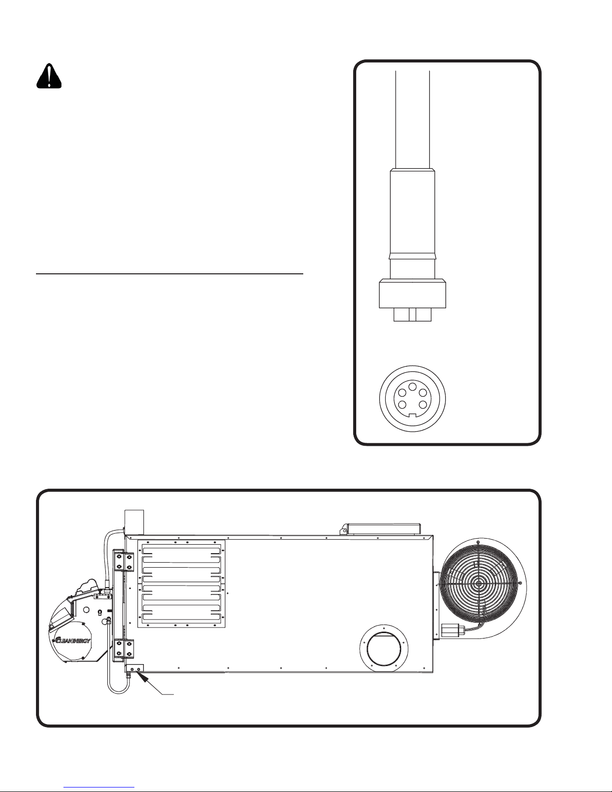
(1) Install a dedicated electrical circuit to the junction box indicated below.
- Front electrical box by the burner on the CE-140, CE-180, and CE-250
- Back electrical box by the blower on the CE-330
(2) Connect the wires according to the label found on the inside of the junction box cover or in
the wire diagrams section of this manual. Use stranded copper wire to ensure a secure
connection.
19
Installing the chimney components:
WARNING: Double wall “Class A” insulated stack must be used through any building
penetration and for any exterior stack. Unapproved stack material and/or installation
can create a fire hazard. Contact Clean Energy Heating Systems, LLC to purchase
approved stack material for your installation.
CAUTION: Using single wall stack on the exterior of your building will cause the stack
gases to cool rapidly and adversely affect the natural draft of the furnace. This will
create a back draft and may damage critical burner components.
(1) Refer to Figure 14 for a typical through-the-roof chimney illustration and Figure 15 for a
typical through-the-wall chimney illustration.
(2) Observe the following requirements when installing the chimney:
• The CE-140, CE-180 and CE-250 furnace models require 6” I.D. stack components.
• The CE-330 furnace model requires 8” I.D. stack components.
• Have a minimum of 10 feet vertical chimney to ensure -.02” w.c. draft over fire.
• Keep horizontal runs short. Slope any horizontal sections at least 1/4” per foot.
• Keep the stack installation simple. Multiple turns and horizontal runs will reduce the
natural draft of the furnace which may damage critical burner components.
(3) Single wall stack may be used inside the building. Observe proper clearances from
combustibles. Do not put single wall stack in areas that may create a burn hazard to
personnel.
(4) Install a barometric damper, as shown in Figures 15 and 16, so that proper draft can be
maintained. Follow the instructions provided with the damper for proper installation.
(5) Use double wall “Class A” insulated stack when making a penetration through the roof or
side wall of your building. Install proper flashing around the exterior penetration of the
stack to make a water tight seal. Clean Energy Heating Systems, LLC recommends
“Dektite” flexible pipe flashing, or equivalent, for through the roof installations.
(6) Install a “Class A” non-restrictive stack cap only.
CAUTION: If your building utilizes an exhaust fan, ensure that there is adequate
make-up air available. Lack of make-up air will create a vacuum in your building
which will result in a back draft at the furnace. A back draft will damage critical burner
components.
FURNACE INSTALLATION
120 V / 60 Hz
Single Phase
30 Amp dedicated circuit
CE-250 CE-330
230 V / 60 Hz
Single Phase
30 Amp dedicated circuit
NOTE: The CE-330 needs a four wire feed. Two 115V Line voltage legs, a neutral, and a
ground.

20
Figure 14: Typical Through-the-Roof Chimney Illustration
Figure 15: Typical Through-the-Wall Chimney Illustration
FURNACE INSTALLATION
10 FT.
3 FT.
(MIN.)
"CLASS A" STACK
COMPONENTS
MINIMUM 10 FT. VERTICAL
STACK HEIGHT TO MAINTAIN
PROPER DRAFT
SINGLE WALL STACK
COMPONENTS
BAROMETRIC
DAMPER
"CLASS A" STACK CAP
NON-RESTRICTIVE TYPE
SET DRAFT
OVER FIRE
AT -0.02
IN. W.C.
CE70022
10 FT.
CE70016
3 FT.
(MIN.)
"CLASS A" STACK CAP
NON-RESTRICTIVE TYPE
MINIMUM 10 FT. VERTICAL
STACK HEIGHT TO MAINTAIN
PROPER DRAFT
BAROMETRIC
DAMPER
SET DRAFT
OVER FIRE
AT -0.02
IN. W.C.
"CLASS A" STACK COMPONENTS
INSTALL AN ADEQUATE
WALL SUPPORT SYSTEM
TO SAFELY BEAR THE
WEIGHT OF THE
"CLASS A" STACK
Other manuals for CE-140
1
This manual suits for next models
3
Table of contents
Popular Furnace manuals by other brands

Whirlpool
Whirlpool WFAU installation instructions

Trane
Trane A801X040AM3SD Installation, operation and maintenance

Carrier
Carrier 59SC2A Product data

SummerAire
SummerAire SBB Installation and owner's operating instructions

Harman
Harman PF-120 owner's manual

Thermo Products
Thermo Products THV1M119A960SA Installation and operation manual

Lennox
Lennox ML180UHV User's information manual

Ferroli
Ferroli ENERGY TOP B Instructions for use, installation and maintenance

Johnson
Johnson 313 instruction manual

Daikin
Daikin DM80VC Service instructions

MORTEX
MORTEX E30 SERIES installation manual

American Standard
American Standard Noncondensing Gas Furnaces User's information guide