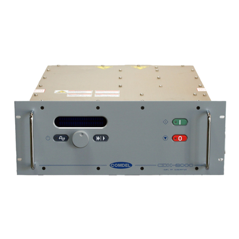
Comdel ESC-2/FP User manual

-~
ARTISAN
®
~I
TECHNOLOGY
GROUP
Your definitive source
for
quality
pre-owned
equipment.
Artisan Technology
Group
Full-service,
independent
repair
center
with
experienced
engineers
and
technicians
on staff.
We
buy
your
excess,
underutilized,
and
idle
equipment
along
with
credit
for
buybacks
and
trade-ins
.
Custom
engineering
so
your
equipment
works
exactly as
you
specify.
•
Critical
and
expedited
services
•
Leasing
/
Rentals/
Demos
• In
stock/
Ready-to-ship
•
!TAR-certified
secure
asset
solutions
Expert
team
ITrust
guarantee
I
100%
satisfaction
All
tr
ademarks,
br
a
nd
names, a
nd
br
a
nd
s a
pp
earing here
in
are
th
e property of
th
e
ir
r
es
pecti
ve
ow
ner
s.
Visit our website - Click HERE

ESC-2 / FP
FP6251RC
ESC-2 / FP
Electrostatic Voltage Source
Full Front Panel Version
Operator’s Manual
Date Revision Detail Author
6-17-03 C Initial release +/- 1KVDC(2KV) @ 3mA RD
2-11-04 C Modified RS232 description 2/11/04 RD
Copyright © 2006 by Comdel, Inc.
The information contained in this manual is proprietary to Comdel, Inc. and is protected by copyright and
trademark laws. You may not modify, copy, reproduce, republish, post, transmit, or distribute in any way any
material from this manual except as may be expressly permitted in writing by Comdel, Inc.
Comdel, Inc. • 11 Kondelin Road, Gloucester, MA 01930 • Phone: 978-282-0620 • www.comdel.com
COMDEL

ESC-2/FP Manual
Table of Contents
1 Introduction.......................................................................1
2 Safety Information............................................................1
3 Unpacking and Inspection...............................................2
4 Installation.........................................................................3
5 Monitors and Indicators...................................................3
6 Cabling...............................................................................3
7 Operating Instructions.....................................................4
A. Local Manual Operation................................................4
B. Remote Manual Operation............................................5
C. Serial Remote Operation ..............................................6
7 System Specifications......................................................7
A. Output Capabilities........................................................7
B. Input Requirements.......................................................8
C. Controls and Features...................................................8
D. System Connections.....................................................8
E. Mechanical Specifications.............................................8
F. Environmental Specifications........................................8
G. Remote Interface Connections.....................................9
8 Certification.......................................................................9
9 Customer Service...........................................................10
List of Figures
FP6251RX.drg ESC-2 Control Drawing
© 2006 Comdel, Inc.

ESC-2/FP Manual
Before installing equipment, carefully read and familiarize yourself with the entire operations manual.
Observe and obey all WARNING and CAUTION notes provided.
1Introduction
This user’s guide and manual includes installation guidelines, operation procedures and voltage requirements.
Also included are safety procedures and cautions during installation, which should be adhered to in order to protect
against injury or warranty violations.
•The ESC-2 Electrostatic Chuck Voltage Source is designed for use in environments where energizing an
existing Electrostatic Chuck is required.
•The ESC-2 is a compact, lightweight system, and is equipped with low stored energy and built-in current
limitations, which safeguard your process from surges and arcs.
•Each ESC-2 also contains parameter adjustments through continuously adjustable controls, and is fully
programmable to give the user maximum flexibility.
2Safety Information
Warning Label and Safety Marking Explanations:
The following symbols and terms may be found on an instrument or used in this manual.
The CE mark indicates compliance with all currently applicable directives and standards.
This label indicates a general warning or caution condition.
This symbol indicates the presence of high voltages in or around the unit.
This symbol indicates a protective earth ground connecting point.
© 2006 Comdel, Inc. 1

ESC-2/FP Manual
The WARNING heading used in this manual explains dangers that might result in personal injury or death.
Always read the associated information very carefully before performing the indicated procedure.
The CAUTION heading used in this manual explains hazards that could damage the unit. Such damage may
invalidate the warranty.
MUST – This word is understood to indicate a mandatory condition.
HIGH VOLTAGE – Voltages greater than 50 volts DC or 25volts AC and known to cause death or serious injury if
contacted.
SERVICE – Any operation of maintenance, repair, calibration or similar activity other than the normal operation of
the unit.
QUALIFIED SERVICE TECHNICIAN,QUALIFIED ELECTRICIAN, QUALIFIED PERSONEL These terms indicate
persons specifically trained to install, service or other wise handle electronic equipment of the character and hazard
potential of this unit.
End User Labeling
The system installer should obtain and apply all appropriate safety and warning labels required by the end user’s
local fire department jurisdiction and Occupational Health and Safety Administration over and above those supplied
by the generator manufacturer.
Read And Understand This Section Fully Before Installing or Operating This Equipment.
WARNING: This equipment must be installed, operated and serviced only by trained, qualified persons.
General Safety Requirements
•WARNING: Due to the presence of high voltages in and around the unit, extreme caution should be exercised
when using and handling this supply.
•CAUTION: There are no user or operator serviceable parts inside this equipment. Refer all service to a
qualified service technician.
•Do not operate the unit with the cover or end panels removed.
•Never operate the ESC-2 with the output cables removed or disconnected.
3Unpacking and Inspection
1. Carefully unpack the unit and inspect for any obvious signs of physical damage that might have occurred
during shipment.
2. Check the outside of the unit for missing or loose mounting screws or broken parts.
3. If there is shipping damage or the unit fails to operate properly upon receipt, report damage to the carrier
immediately and notify Comdel factory within 30 days of receipt of unit. Failing to report any damage within
this time period is the same as acknowledging that the unit was received undamaged.
© 2006 Comdel, Inc. 2

ESC-2/FP Manual
4. If returning the product for repair you must:
•Return the unit in the original, or equivalent, shipping container
•Receive a Return Materials Authorization (RMA) number from the factory prior to the return of the
product to Comdel for repair
•Place RMA numbers clearly on the shipping container or on the packing slip
CAUTION: Breaking the seal or removing the warranty decal from this unit will void the warranty. If internal
damage is suspected, contact factory for assistance.
4Installation
The ESC-2 may be located in any convenient location and in any orientation. This unit does not require outside
cooling or airflow. The system requires a single 24Vdc power source capable of delivering 1A continuous (3 A
peak for 1 sec at start up of ESC) to operate. A 3 pin Molex connector/cable assembly is supplied with each unit.
The power connection is reverse polarity projected, as is the ESC-2 internally. Connection orientation of the power
leads does not effect the operation or present a possible fault condition.
All output connections are via standard BNC jacks located at the rear of the unit. Shielded cable is
recommended for high noise environments.
The ESC-2 is designed to run in either bipolar or unipolar output configurations. Thus, the load may be connected
from each HV connector to the center tap connection (bipolar) or from one HV connector to the other (unipolar).
Since this system has a fully floating output, the center tap point may be attached to an electrical bias within the
range of -500V to +500V. For bipolar applications it is important to make sure the load impedance from each HV
terminal to the center tap reasonably match. This assures proper output voltage balance and regulation.
CE Installation Specifics
This equipment must be installed in accordance with the directives of prEN50178 and EN60204 / IEC-204-1.
5Monitors and Indicators
The ESC-2 makes analog outputs available representing output differential voltage (the voltage present from the +
to - output terminals), + terminal output current, - terminal output current and center tap voltage (voltage float from
the center tap terminal with respect to chassis). Outputs are scaled as 0-10Vdc representing 0 - full output for the
differential voltage and + and - current monitors. The center tap voltage monitor is scaled as 0-5Vdc = -500 to +
500 Volts.
Also available is a high voltage “ON” indicator. This is an emitter/collector pair from an opto-isolator. When in the
conducting state it indicates that the high voltage has been enabled. Indication is provided for output polarity. When
in the high state (+15v) this indicates a positive output polarity. When in a low state (0v) this indicates a negative
output polarity.
6Cabling
Output cables should be high quality RG-58/A type cable. The mating high voltage output connectors are standard
BNC type for the center tap connection and MHV high voltage connectors for the HV+ and HV- outputs . Output
cables should be kept to a length of 10 feet or less, each.
© 2006 Comdel, Inc. 3

ESC-2/FP Manual
Interface signals are brought to the ESC-2 at the rear panel, through a DB25S connector for manual (analog)
remote operation or through a DB9S connector for serial (RS-232C) remote operation.
7Operating Instructions
The ESC-2 is designed as a fully functional stand alone voltage source. Operation may be in one of the following
modes: A) Local Manual operation via the front panel controls, B) Remote Manual operation via the rear panel
analog interface connector and C) Serial Remote operation via the RS-232c remote connection at the rear panel.
Since most of the operational functions are similar for each mode, the following guidelines apply to all three modes
of operation:
•After power up, the ESC-2 defaults to a disabled state. This assures a safe starting point with no high voltage
output present.
•Before enabling high voltage, the output relays should be set to their required state. This includes the output
discharge relay and the output polarity selection relay. The default condition for polarity in any of the three
modes is positive output at the positive BNC connector. The default for the discharge circuit in remote manual
mode is “output clamped”. This means that the output terminals are connected to ground via the relay and
internal resistor network. In local mode the discharge relay defaults to “output ready” or not clamped. In local
mode, both the polarity selection and discharge function default to automatic operation (controlled by the
ESC-2’s internal microprocessor). The automatic operation can be disabled via the front panel function
selectors. When automatic operation is disabled, these functions are still operational from the rear panel. In
normal use, these functions should only be activated before and after disabling high voltage. This will prevent
arching across the relays, which shortens useful life.
•It is important to note that in manual remote mode, the discharge signal is also used as a high voltage lock
out. This forces the high voltage to a disabled state when the discharge relay is activated. The remote
discharge input must be active to allow the unit to be enabled. The discharge signal should NOT be used as
a high voltage enable signal. High voltage enable functions should be left to their designated input pins.
•Set points are included for both output voltage and output current in all modes. A value greater than “0” must
be set for each to obtain output. Remote set-points are scaled a 0-10Vdc = 0-full output. In local mode the
defaults are 50 Volts and 3 mA settings. In any remote mode, the defaults are 0 Volts and 0 mA. The order
of application of set-points is not important but both are required.
•In actual system operation, the set-points can be applied at any time before or after the application of the high
voltage enable signal. It is important to remember that remote manual mode does not have a ramp-up or
ramp-down function. If the voltage set point is present when high voltage is enabled, the output will
immediately jump to the level set. If a ramp is needed, the setpoint should be ramped via an external source
from 0 to its final value, after enabling high-voltage. For capacitor loads a ramp can be established by limiting
the available output current. By setting the voltage set point to the desired final value and the current set-
point to some particular limiting value, the output will charge the capacitance as: Time to rise to Vset =
[capacitance x final voltage]/Current limit setting. In this condition the output will ramp up when high voltage is
enabled.
A. Local Manual Operation
Local manual operation is performed using the front panel control functions on the unit. Upon supplying a live
24Vdc source to the rear panel power connector, the unit will automatically initialize and default to the Remote
Manual (RM) mode. For instruction on Remote Manual mode, see Section VI. B.
1. Enter Local manual (LC) mode by depressing the >> button once.
© 2006 Comdel, Inc. 4
ESC-2/FP Manual
2. The first menu screen will allow you to set the output voltage (Vset) with the front panel knob. By
turning the knob clockwise, the voltage setting increases. The minimum setting is 25V, the
maximum, 2000V. The default setting is 50V. The voltage setting changes in 10V increments.
3. Pressing the > button once will activate the Ilim setting screen. Turning the front panel knob
counter-clockwise will decrease the current limit setting. The current setting changes in 0.1mA
increments. The output current (Ilim) may be set to any value from 0.1mA to 3mA. The default value
is 3mA.
4. Pressing > again will access the ramp-up (RMUP) setting screen. This adjusts the output voltage
rise (from 0 to final set point) over the range of .1 second to 9.9 seconds. Turning the program knob
clockwise increases the ramp-up time. The ramp-up starts as soon as high voltage is enabled. The
default is .1 seconds.
5. Pressing > will access the ramp-down (DNRM) setting. This adjusts the time it takes the output to
return to 0 from its present setting. This is adjusted over the range of .1 to 9.9 seconds by turning
the knob clockwise. The ramp starts when the HV enable is removed. The default is .1 seconds.
6. By pressing the > button again, the auto discharge (ADIS) feature may be accessed (default is ON).
Turning the program knob selects ON or OFF. The auto discharge circuit dumps the output voltage
through a relay/resistor network each time the HV enable is removed. Note that the auto discharge
will activate each time the HV enable is removed, and occur at the end of the down-ramp cycle.
7. The final selection screen can be accessed by pressing >. This is the auto voltage reversal (AREV)
function. Turning the program knob selects ON or OFF. This function automatically reverses the
output voltage polarity each time HV is enabled.
Once all of the appropriate settings have been entered, the unit is enabled by pressing the enable button,
located to the left of the program knob. Pressing this button again will disable the unit.
B. Remote Manual Operation
The ESC-2 may be run entirely by the remote operation functions by connecting your controller interface to the
rear panel Analog INTERFACE connector (DB25S). This requires a minimum of the following signals:
•Voltage set point (0-10Vdc analog)
•Current limit set point (0-10Vdc analog)
•HV enable (digital 24Vdc signal where enable + 24V present)
•HV discharge circuit enable (digital 24Vdc signal where disable = 24V present)
Typical remote operation is as follows:
1. Upon applying 24Vdc power, the unit will initialize to the default remote manual (RM) mode.
2. Apply an analog voltage between Interface Pins 14 and 1 of 0-10Vdc. This will request 0-2000Vdc
output.
3. Apply an analog voltage between Interface Pins 15 and 2 of 0-10Vdc. This will set the output
current limit to a level of 0-3mA. Normally, a 10Vdc level would be set to allow full output current
operation.
4. Apply a 24Vdc signal between Interface Pins 20 and 8 to disable the HV discharge relay.
5. Apply a 24Vdc signal between Interface Pins 18 and 6 to enable the HV output. Removing this
signal will disable HV.
6. After disabling HV, the output may be discharged by removing the 24Vdc signal between Interface
Pins 20 and 8. Discharge is via 200KOhms. Discharging the output while the unit is enabled will
cause the output to be immediately disabled, and the output to be discharged as a safety feature.
CAUTION: It is not recommended that the discharge utility be used as the enable/disable function of the unit.
7. At any time during system disable, a 24Vdc signal may be applied between Interface Pins 19 and 7
to reverse the output polarity.
© 2006 Comdel, Inc. 5

ESC-2/FP Manual
CAUTION: Changing polarity during operation is not recommended.
The output polarity reversal feature may be disabled in all modes by connecting Pin 11 to Pin 10 at the rear
panel remote connector.
Remote Analog Interface Connections:
Signal Pin Function
1 Voltage set point, analog return
14 Voltage set point, analog positive (10V full scale)
2 Current set point, analog return
15 Current set point, analog positive (10V full scale)
3 Output voltage monitor (10V full scale)
16 Center tap terminal voltage monitor (See NOTE1)
4 Positive output current monitor (10V full scale)
17 Negative output current monitor (10V full scale)
5 Monitor circuit analog return
18 HV enable digital input positive (24Vdc digital)
6 HV enable digital return
19 Polarity change digital positive (24Vdc digital)
7 Polarity change digital return
20 Discharge command digital positive (24Vdc digital)
8 Discharge command digital return
21 HV on indicator positive, open collector (40Vdc/50mA max. rating)
9 HV on indicator negative, open emitter
22 Output polarity monitor (+15v=pos/0v=neg)
10 Polarity indicator return/ground
23 No connection
11 Polarity disable
24 +15Vdc source (25mA max.)
12 +15Vdc source (25mA max.)
25 Circuit common / 15v return
13 Circuit common / 15v return
NOTE1:The center tap voltage monitor is currently set for a 0-5Vdc scale with a nominal 2.5Vdc offset
representing 0Vdc actual at the center tap terminal. Thus, the center tap monitor will have a 0Vdc output for -
500Vdc actual at the center tap terminal, and a 5Vdc output for +500Vdc actual at the center tap terminal.
C. Serial Remote Operation
The operation sequence for serial mode is similar to “Local Manual” operation. Full remote operation is
available over serial RS-232C interface via the real panel 9-pin connector (DB9S). The serial interface
provides all of the features found on the front panel menus.
CAUTION: The default communication protocol is factory set at 9600 baud, 8 bits, 1 stop bit, no parity. These
settings can be changed via internal dip switches. Contact Comdel Engineering for assistance if other protocol
settings are required. Any attempt to change factory settings will void any warranty on the unit.
The following is a description of the RS-232 ASCII instruction set to operate the ESC-2.
1. All incoming instructions need to be terminated with a carriage return (HEX 'D') except for the
ATTENTION (!) and EXIT (#) commands.
2. The interface does not normally require handshaking for it's input because it is interrupt driven with a 1K
buffer.
© 2006 Comdel, Inc. 6

ESC-2/FP Manual
3. The (PROMPT) response is defined as: <LF><CR> > orHEX A, D, & 3E
ESC-2 Serial Remote Commands
Instruction Function Response
! (NO <CR>) ATTENTION (PROMPT)
SVxxxx SET OUTPUT VOLTAGE (1) (PROMPT)
SIxxx SET CURRENT LIMIT
(2) (PROMPT)
D+ ENABLE AUTO DISCHARGE (PROMPT)
D- DISABLE AUTO DISCHARGE (PROMPT)
V+ ENABLE AUTO VOLTAGE REVERSAL (PROMPT)
V- DISABLE AUTO VOLTAGE REVERSAL (PROMPT)
EV ENABLE VOLTAGE (PROMPT)
DV DISABLE VOLTAGE (PROMPT)
P+x.x SET UPRAMP TIME (3) (PROMPT)
P-x.x SET DOWNRAMP TIME (4) (PROMPT)
RV READ VOLTAGE xxxx (PROMPT)
RB READ CENTER TAP VOLTAGE xSPxxx (PROMPT)
R+ READ POSITIVE CURRENT xxxx (PROMPT)
R- READ NEGATIVE CURRENT xxxx (PROMPT)
EE ENABLE ECHO (PROMPT)
DE DISABLE ECHO (PROMPT)
EX EXIT NONE
# (NO <CR>) EXIT <CR><LF>BYE
To initialize serial communications a “!” character must first be transmitted to the ESC-2. The front panel will
display SR to indicate serial remote mode. An “H” character will display the HELP screen with all available
functions and commands.
NOTES:
1. The minimum output default is 50Vdc. Settings of less than 0050 will yield 0Vdc. Voltage changes are in
1Vdc increments.
2. The minimum current limit setting is 0.1mA.
3. The minimum ramp settings are 0.1 seconds.
4. Values less than 0.1 will default to 0.1 seconds.
8System Specification
A. Output Capability
Description Specifications
True floating bi-polar output: Minimum path to chassis ground from any HV output terminal
>10 Meg ohm
Output to input isolation: > 500 Meg ohm (based on standard 5 KV dc hi-pot tests)
Output voltage/current: +/- 1000 VDC, 3mA maximum limit
Output stability: 0.1% or better of output from 0 to full load
Output ripple: Less than 0.2% at 50k Hz operating frequency
Output linearity: Better than 0.1% full scale
Output polarity reversal: On command
Output voltage balance: Better than 0.5% for matched loads
B. Input Requirements
Single 24 Volt dc, 1 Adc (2 amp surge capability for 2 seconds at start up).
© 2006 Comdel, Inc. 7

ESC-2/FP Manual
C. Controls and Features
1. All control features are available local (front panel) and remote (25 pin d-type connector).
2. All analog set-point and monitor signals are available as 0-5v or 0-10v full scale and are fully differential.
Inputs are 200k ohm min. Outputs are capable of driving 1k ohm at 10v max.
3. All command lines and status indicators are uncommitted optically isolated digital signals. (All signals are
active true).
4. Continuously variable output voltage set point.
5. Continuously variable output current limit.
6. Hi-voltage enable command.
7. Hi-voltage enabled indicator.
8. Output polarity reversal command and disable.
9. Output discharge command.
10. Output voltage (differential) monitor.
11. Center tap voltage monitor.
12. Positive terminal output current monitor.
13. Negative terminal output current monitor.
14. Output protection: Active voltage and current limits in addition to 330k ohm output limiting impedance.
15. RS-232c Serial Interface for all remote control functions.
D. System Connections
Description Specifications
DC power input: 3 pin Molex type, non reversible quick disconnect. Molex P/N -
Consult Factory
DC output: MHV connectors for HV+ and HV-, BNC connector for HV-CT
Remote interface: 25 pin D-type female (DB-25f)
Fusing Requirements: 1Amp 3ag or equivalent
E. Mechanical Specifications
Description Specifications
Size: 8" W x 3.25" H x 6.25" D approx.
Weight: 2 lbs. approx.
Cooling: Free air
F. Environmental Specifications
Operating Temperature & Humidity
Operating ambient temperature: 0 to 45°C
Humidity: 10-90% non-condensing
Storage and Transportation
Storage temperature/humidity/air pressure: 0 to +70°C
© 2006 Comdel, Inc. 8

ESC-2/FP Manual
G. Remote Interface Connections
Signal Pin Function
1 Voltage set-point input, analog return
14 Voltage set-point input, analog positive
2 Current limit set-point input, analog return
15 Current limit set-point input, analog positive
3 Output voltage monitor, analog positive
16 Center tap terminal voltage monitor, analog positive
4 Positive terminal current monitor, analog positive
17 Negative terminal current monitor, analog positive
5 Monitor circuits, analog return
18 HV enable input, positive input
6 HV enable, negative input
19 Polarity change command, input positive
7 Polarity change, input negative
20 Discharge command, input positive
8 Discharge command, input negative
21 HV indicator output, open collector
9 HV indicator output, open emitter
22 No connection
10 No connection
23 No connection
11 No connection
24 +15Vdc
12 +15Vdc
25 Control circuit common ground
13 Control circuit common ground
Addendum for ESC-2/FP - 2KV Systems.
Front Panel Display—Scaling:
1. Voltage setpoint and monitor scaling: The voltage setpoint and ouput monitor displays read at full scale
as 2.00, this implies an output of 2000 volts dc from HV+ to HV- terminal. The scaling is linear throughout
its entire range. Thus, .10 represents 100vdc and .05 is 50vdc output.
2. Current setpoint and monitor scaling: The current setpoint and I+ and I- ouput monitor displays read at
full scale as 3.0, this implies an output of 3mA dc from either HV+ to HV- terminal. The scaling is linear
throughout its entire range. Thus, .1 represents .1mA dc.
9Certification
1. This unit carries the ETL safety compliance mark to UL standard UL-1012.
2. This unit is designed and labeled in compliance with CE mark certification requirements. The
manufacturer will supply a Declaration of Conformity as required.
© 2006 Comdel, Inc. 9

ESC-2/FP Manual
10 Customer Service
Comdel field services, technical support, and repair services are available to all customers and for both warranty
and non-warranty products. When sending equipment to the factory for service or calibration, you need a Return
Material Authorization (RMA) number to ensure that we can properly track your equipment.
Technical Support
Technical support is available by phone during regular business hours at any one of our worldwide field offices or
authorized agents.
Comdel Support on www.comdel.com
The Comdel website offers a complete list of sales and service offices, product troubleshooting tips through the
Frequently Asked Questions (FAQ) page, an online request form for RMA numbers, and access to RF & DC
product manuals.
Factory Service & RMA Information
Comdel field services, technical support, and repair services are available to all customers and for both warranty
and non-warranty products. When sending equipment to the factory for service or calibration, you need a Return
Material Authorization (RMA) number to ensure that we can properly track your equipment.
Obtaining an RMA Number
•To complete an online request for an RMA number log on to www.comdel.com and click on Factory
Service under the Sales & Service Menu or for direct access go to
http://www.comdel.com/pages/sales/rma.php4
•Call 978-282-0620 or 800-468-3144. If this is a machine-down situation, call the factory immediately.
Note: We will respond to all e-mail requests by the next business day.
Customer Support and Worldwide Office Contacts
For customers located within the United States, you can reach us by phone, fax, or e-mail.
Corporate Headquarters ♦(Authorized Repair Depot)
11 Kondelin Road
Gloucester, MA 01930
Phone 800-468-3144 or 978-282-0620 (M-F 8:00 a.m. - 5:00 p.m.EST)
Fax: 978-282-4980
Comdel US Regional Office
Comdel California, USA ♦(Authorized Repair Depot)
Phone: 408-727-5254
Fax: 408-727-4433
For customers located outside the United States, please contact your local Comdel office or Distributor. (Consult
attached directory.)
© 2006 Comdel, Inc. 10

ESC-2/FP Manual
International Support
We currently provide authorized product repairs and technical support through the following International Comdel
locations marketed with ♦Authorized Repair Depot (ARD). These offices have experienced technicians that can
assist in arranging for product returns or on-site assistance.
The Comdel authorized repair depots stock parts and test equipment that support most Comdel products.
Customers are encouraged to discuss specific service support needs with their local Comdel office to ensure prior
product support preparation is arranged.
Other Comdel sales and service distributors are available to support facilitating return of Comdel products to the
most appropriate service repair depot.
Comdel authorized depots offer application support, RF training, and product design assistance. All are fully
supported by the product marketing and engineering team at Comdel’s headquarters.
International Offices
EUROPE
Comdel United Kingdom ♦(ARD)
Phone: +44-1256-766914 or +44-1256-766917
Fax: +44-1256-766915
Email: [email protected]
MIDDLE EAST
Israel
Odem Scientific Applications Ltd.
Phone: +972-8-9366101
Fax: +972-8-9366102
Email: [email protected]
ASIA
Comdel Seoul, Korea ♦(ARD)
Phone: +82-2-565-4780
Fax: +82-2-564-5398
Email: [email protected]
Singapore/Malaysia
DAL Engineering (S) PTE, Ltd. ♦(ARD)
Phone: +65-6-743-5538
Fax: +65-6-743-5539
Email: [email protected]
Taiwan, ROC
FairTech Corp. ♦(ARD)
Phone: +886-3-5723257
Fax: +886-3-5727302
Email: [email protected]
China
Beijing Leyfond Vacuum Tech. Co., Ltd.
Phone: +86-10-82843366
Fax: +86-10-82842835
Email: [email protected]
JAPAN
Comdel Branch Office Japan ♦(ARD)
Phone: + 81-47-369-9393
Fax: +47-369-3317
Email: [email protected]
PRA Ltd. ♦(ARD)
Phone: +47-369-3389
Fax: +47-369-3317
© 2006 Comdel, Inc. 11

ESC-2/FP Manual
Comdel Warranty
Seller fully warrants that equipment, service, software, repair or parts supplied shall conform to the description in
the quotation and agrees to repair or replace F.O.B. shipping point, any parts (excepting expendable items such as
semiconductors and vacuum devices), services, or repairs that fail due to defects in material or workmanship within
(1) one year of start-up of equipment or (24) twenty four months after shipment, whichever occurs first, or in the
case of service or repair, within (1) one year of rendering service or repair. At Buyers request, failure analysis will
be provided for all in-warranty failures returned by Buyer to Comdel Gloucester. Liability of Seller under this
warranty shall exist provided that: Buyer exposes the product to normal use and service; in case of shipping
damage, Buyer notifies Seller within 30 days of receipt of goods; the Buyer receives a Return Materials
Authorization (RMA) number from Seller prior to the return of product for repair; if upon examination of such
product by Seller it is disclosed that a defect in materials and/or workmanship does exist, and the defect in the
product was not caused by improper conditions, misuse, abuse or negligence; and that Sellers warranty decals
have not been removed or tampered with and the equipment has not been repaired or modified by anyone other
than Seller’s authorized personnel. Other than those expressly stated herein, there are no other warranties of
any kind, expressed or implied, and specifically excluded, but not by way of limitation, are the implied
warranties of fitness for particular purpose and merchantability.
It is understood and agreed that Seller’s liability, whether in contract, in tort, under any warranty, in
negligence or otherwise shall not exceed and Buyer’s remedy is limited to either (i) repair or replacement of
the defective parts F.O.B. shipping points, correction of the defective service or repair, or at Seller’s option
(ii) return of the product and refund of the purchase or service price. Under no circumstances shall Seller
be liable for special, indirect, incidental, or consequential damages. The price stated for the equipment,
service, repair or parts is a consideration in limiting Seller’s liability. No action, regardless of form, arising
out of the transactions of this agreement may be brought by Purchaser more than one year after the cause
of action has accrued. The warranty for the equipment, service, repair or parts proposed in this quotation is
as stated in the above paragraphs. It is not re-stated nor does it appear in any other form.
© 2006 Comdel, Inc. 18

19
© 2006 Comdel, Inc.

Artisan
Technology
Group
is
an independent supplier
of
quality pre-owned equipment
Gold-standard
solutions
Extend the life
of
your
critical industrial,
commercial, and military systems
with
our
superior service and support.
We
buy
equipment
Planning to
upgrade
your current
equipment? Have surplus equipment taking
up shelf space? We'll give it a
new
home.
Learn
more!
Visit us at artisantg.com for more info
on price quotes, drivers, technical
specifications, manuals, and documentation.
Artisan Scientific
Corporation
dba
Artisan
Technology
Group
is
not
an affiliate,
representative,
or
authorized
distributor
for
any
manufacturer
listed herein.
We're here to make your life easier.
How
can
we
help you today?
(217)
352-9330
Isales@artisantg.com Iartisantg.com
Table of contents
Other Comdel Portable Generator manuals
Popular Portable Generator manuals by other brands

Energizer
Energizer eZV Series user guide

CGM
CGM S12000DUAL user manual

Winco
Winco ULPSS15B2W Installation and operator's manual

Generac Portable Products
Generac Portable Products GP Series owner's manual

Middle Atlantic Products
Middle Atlantic Products RLM30-L5 0-1 Series instruction sheet

Ruris
Ruris R-POWER GE2800 manual

Nilar
Nilar Ferroamp Home Box instruction manual

CIAT
CIAT GGS A050 Ch 45 Installation, Operation, Commissioning, Maintenance

Wolf
Wolf POWERTECH PS200 instruction manual

Clarke
Clarke FG4050ES Operation & maintenance instructions

Energizer
Energizer HardCase Professional Everest 500 user guide

Carrier
Carrier ASPDS1CCL035 owner's manual