1
1.0
INTRODUCTION
t is recommended that personnel study this
manual before attempting to operate, clean
or sterilize the MicroPower™ High Speed
Drill and accessories. The safe and effective use
of this equipment requires the understanding of
and compliance with all warnings, cautionary
notices, and instructions marked on the product,
and included in this manual.
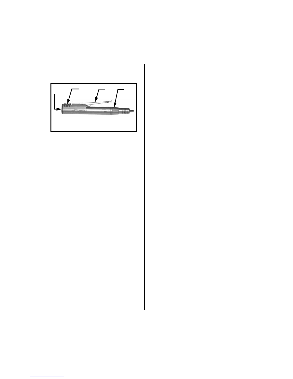
1.1 Intended Use
he MicroPower High Speed Drill, which
operates in conjunction with assorted bur
guards, burs and drill bits, is designed to
perform bone cutting, drilling, and soft tissue
resection.
This handpiece can be operated using the
PowerPro
®
(PRO2000/PRO2000I), the E9000
®
(E9000, E9000G, E9000J) or Advantage
®
(D3000, D3000I, D3000J) Controllers.
The MicroPower
High Speed Drill is intended
for small bone procedures such as:
Arthroscopic, Neurosurgical, Orthopedic
(hand, wrist, foot and ankle) and Plastic /
Reconstructive.
1.2 Warnings and Cautions
This equipment is designed for use by medical
professionals completely familiar with the
required techniques and instructions for use of
the equipment.
Read and follow all warning
and cautionary notices and instructions
marked on the product and included in this
manual.
Service intervals, as listed in
“Table 2:
Maintenance Schedule” on page 20
, are
required to keep the MicroPower High Speed
Drill and attachments at their optimum
operating performance.
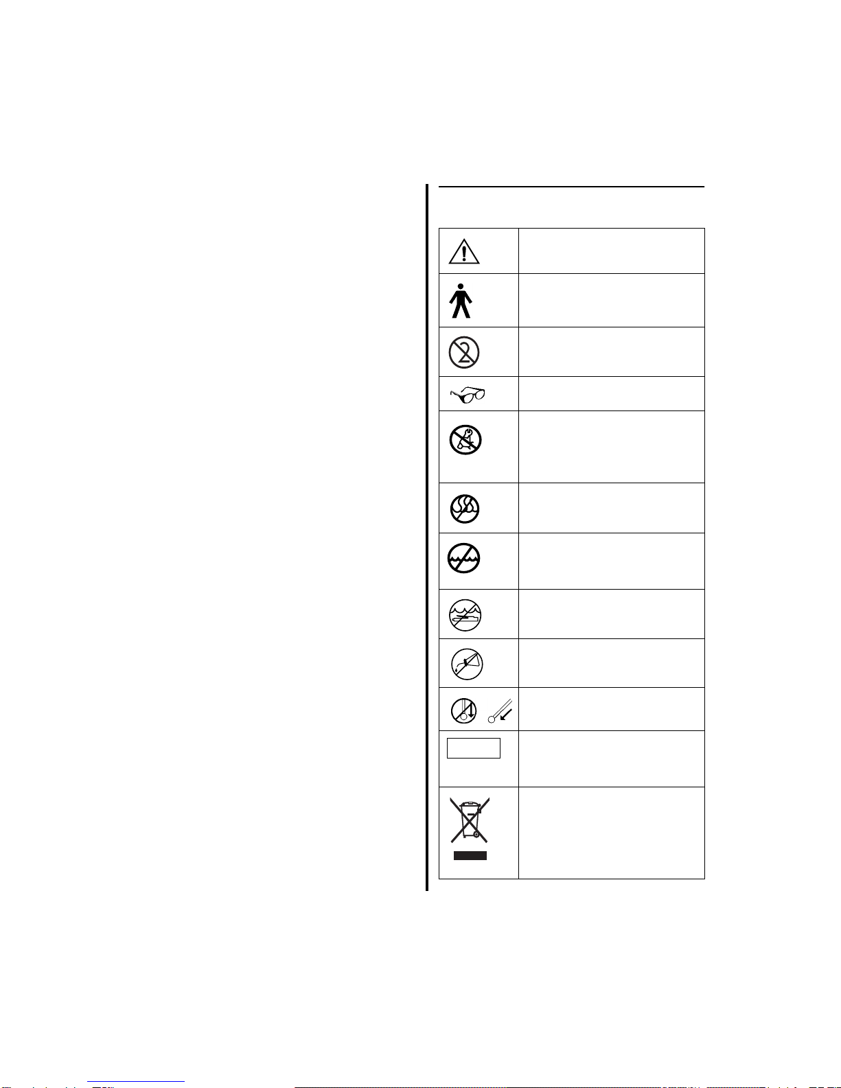
1.2.1 Warnings
1. Eye protection is always
necessary when operating
equipment. Eye injury may result.
2.
Continually check
all handpieces and
attachments for overheating. If overheating
is sensed, immediately discontinue use and
return equipment for service. Overheating
of the bur, bit or blade may cause damage to
the bur, bit or blade and may cause thermal
necrosis.
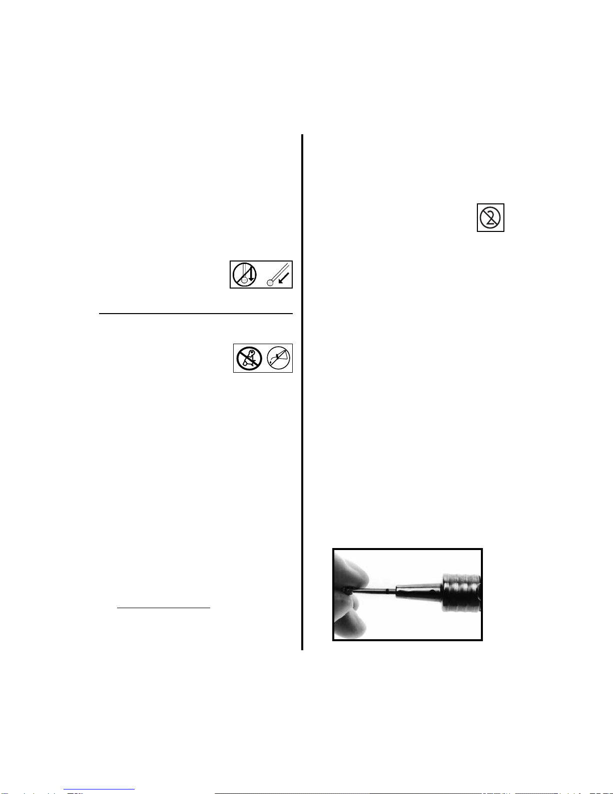
3. Do not attach, insert or remove attachments
or accessories while the handpiece is oper-
ating. Serious injury may occur.
Place the
handpiece safety mechanism to the safe
position prior to installation or removal
of items
.
4. Do not immerse handpieces in fluids.
I
T