Country Home Products DR TRIMMER/MOWER SPRINT Quick reference guide

DR®TRIMMER/MOWER™
Assembly & Operating Instructions
Model: • SPRINT®
Please read these instructions and the Engine Manufacturer's Owner's Manual before
you assemble and use your DR®TRIMMER/MOWER™.


DR®TRIMMER/MOWER™Assembly & Operating Instructions i
And congratulations on your purchase of a new DR®
TRIMMER/MOWER™!
We have done our utmost to ensure that your DR®will be one
of the most trouble-free and satisfying pieces of equipment you
have ever owned.
Please let us know of any questions or problems you may have.
We want to answer or correct them as quickly as possible.
(When you do call or write, please have your serial number
and/or order number handy—it will speed things up!) We also
hope to hear from you on how much you like your new helper.
And please tell your friends about your new DR®TRIMMER/
MOWER™. Having DR®Owners spread the word about our
products and our way of doing business is the best advertising
we can have, and it's the best way to help us provide even
better service in the years to come.
Thanks once again!
for all of us at...
COUNTRY HOME PRODUCTS®

ii DR®TRIMMER/MOWER™Assembly & Operating Instructions

DR®TRIMMER/MOWER™Assembly & Operating Instructions iii
Table of Contents
SAFETY INSTRUCTIONS...............................................................................................................................................1
Dress Appropriately.........................................................................................................................................................1
Preparation.......................................................................................................................................................................1
Operating the Machine Safely .........................................................................................................................................1
Safety with Gas-Powered Machines................................................................................................................................2
Warning to All California and Other Users.....................................................................................................................2
TRIMMER PARTS & COMPONENTS..........................................................................................................................3
ASSEMBLY COMPONENTS...........................................................................................................................................4
ASSEMBLY........................................................................................................................................................................5
CONTROLS & FEATURES...........................................................................................................................................10
STARTING & OPERATING..........................................................................................................................................11
Electric-Starting.............................................................................................................................................................11
Manual-Starting.............................................................................................................................................................11
Stopping the Engine.......................................................................................................................................................12
Engaging the Trimmer Head..........................................................................................................................................12
Stopping the Cords from Spinning ................................................................................................................................12
Cutting Cords.................................................................................................................................................................13
TRIMMING AND MOWING METHODS....................................................................................................................14
Obstacles........................................................................................................................................................................14
Mow-Ball™Support.......................................................................................................................................................14
Cutting Cords.................................................................................................................................................................14
Adjusting the Cutting Height.........................................................................................................................................16
Wagner Anti-Wrap Device............................................................................................................................................17
Heavy Growth................................................................................................................................................................18
Wet Conditions..............................................................................................................................................................18
Very Dry Conditions......................................................................................................................................................18
Slopes.............................................................................................................................................................................18
Windrows.......................................................................................................................................................................19
Firebreaks ......................................................................................................................................................................19
End-of-Season Garden Clean-Up ..................................................................................................................................19
MAINTENANCE..............................................................................................................................................................20
Regular Maintenance.....................................................................................................................................................20
Battery Care (Electric-Starting models only).................................................................................................................21
To Remove the Mow-Ball™Support Assembly ............................................................................................................22
To Reassemble the Mow-Ball™Support Assembly.......................................................................................................23
To Partially Lower the Bearing Housing Assembly (to remove debris)........................................................................24
To Check the Bearing Housing Assembly for Damage.................................................................................................24
To Remove and Replace the Bearing Housing Assembly .............................................................................................25
To Replace the Belt .......................................................................................................................................................26
To Adjust the Belt Tension Using the Trimmer Control Cable.....................................................................................27
TROUBLESHOOTING...................................................................................................................................................28
PARTS LIST.....................................................................................................................................................................32
SCHEMATIC DRAWING ..............................................................................................................................................33
DAILY CHECKLIST FOR THE DR®TRIMMER/MOWER™...........................................................BACK COVER


DR®TRIMMER/MOWER™Assembly & Operating Instructions 1
Safety Instructions
We want you to enjoy years of productive use from your DR®TRIMMER/MOWER™. We don't
want you to get injured, so please take a few moments to read the following guidelines for safely
operating your new machine.
Dress Appropriately
·Always wear protective goggles (provided with your DR®TRIMMER/MOWER™) while
mowing, to protect your eyes from possible thrown objects.
·Wear shoes with non-slip treads when using your DR®TRIMMER/MOWER™. If you have
safety shoes, we recommend wearing them. Do not use the machine while barefoot or wearing
open sandals.
·Wear long pants while trimming, and avoid wearing loose clothing or jewelry that might get
caught on the mower's moving parts.
·Use ear muffs or ear plugs to protect your valuable hearing.
Preparation
·Read these Assembly & Operating Instructions and the Engine Manufacturer's Owner's Manual
before you use the DR®TRIMMER/MOWER™. Become familiar with the controls, engine and
service recommendations to ensure the best performance from your machine.
·Inspect the area you'll be working in for hidden objects such as large rocks, logs, rope, wire,
garden tools, etc., and remove these obstacles before mowing. Do not attempt to mow over
obstacles as this could damage the machine and cause injury.
Operating the Machine Safely
·Only use the DR®TRIMMER/MOWER™for trimming and mowing grass, weeds, and other
growth as specified in this manual.
·Use only manufacturer-recommended replacement parts and accessories.
·Never bend, cut, fit, weld, or alter the DR®TRIMMER/MOWER™in any way. Modifications to
your machine could cause personal injuries and property damage, and may void your warranty.
·ALWAYS shut off the engine and remove the spark plug wire prior to making any adjustments
to the machine. If you have to stop to remove grass or debris from the underside of the deck,
ALWAYS disconnect the spark plug wire first.
·The exhaust area on the engine becomes very hot. Allow the engine to cool before doing
maintenance or making adjustments.
·When operating over uneven terrain and slopes, use EXTREME CAUTION and ensure solid and
firm footing at all times.
·Use extra caution when mowing in wet, slippery conditions.
·Turn off the engine whenever you leave the operating position. Never leave the engine running
when refueling, changing cords or working on the machine.

2DR®TRIMMER/MOWER™Assembly & Operating Instructions
·As with any trimmer, the tips of the cutting cords on the DR®TRIMMER/MOWER™can throw
sticks, small stones, gravel, and bits of debris for long distances at great velocity. The faster the
cutting cords are spinning, the farther debris may be thrown. Do not move over loose materials
such as gravel or mulch with the trimmer head spinning. Doing so could cause personal injury or
property damage from thrown objects.
·Never allow children or animals near the work area. Keep at least 50 feet clear of bystanders,
and always turn the machine off when someone approaches to avoid causing injury from thrown
objects.
·Never allow children or people unfamiliar with these instructions to use the DR®TRIMMER/
MOWER™.
·Be cautious when using your DR®TRIMMER/MOWER™around fencing, wires, ropes, and
hoses. It is possible that these and other debris can become wound around the shaft of the
machine, potentially damaging the bearings or injuring the operator.
·Use the machine only in daylight or good artificial light.
·Never operate the machine with a damaged shield or without the shield in place.
·Do not operate the machine when under the influence of alcohol or medication.
·Watch for traffic when mowing near roadways.
Safety with Gas-Powered Machines
·Do not run the engine in an enclosed area or without proper ventilation.
·Store all fuel in containers specifically designed for this purpose. Plastic containers are more
likely to prevent sediment and condensation problems.
·Refuel outdoors only, and do not smoke while refueling or operating the machine.
·If gas is spilled, do not attempt to start the engine. Move the machine away from the area of the
spill and avoid creating any source of ignition until the gas vapors have dissipated. Wipe up any
spilled fuel to prevent a fire hazard, and properly dispose of the waste.
·Allow the engine to cool completely before storing in any enclosure. Never store the machine
with gas in the tank near an open flame or spark.
·Do not change the engine governor settings or modify the engine speed.
·Some state and local regulations require the use of a spark arrester on gas powered
engines. Contact your local fire marshal or forest service for specific information
pertaining to your area. If you are required to use a spark arrester, please contact one of
our Customer Service Representatives for assistance in obtaining and installing one.
Warning to All California and Other Users
Under California law, and the laws of some other states, you are not permitted to operate an internal
combustion engine using hydrocarbon fuels without an engine spark arrester. All DR®TRIMMER/
MOWERS™shipped to California and Washington state are provided with spark arresters. Failure
of the owner/operator to maintain this equipment in compliance with state regulations is a
misdemeanor under California law and may be in violation of other state and/or federal regulations.
Contact your local fire marshal or forest service for specific information in your area.

DR®TRIMMER/MOWER™Assembly & Operating Instructions 3
Trimmer Parts & Components
The following parts and assembly components should be in your DR®TRIMMER/MOWER™
package. Please check your shipping box(es) and parts package(s) for the items listed below. If
your shipment is incomplete or if you have any questions, please call us TOLL-FREE 1(800)DR-
OWNER (376-9637).
Assembly Components:
1—Upper Handlebar [#117761]
1—Lower Handlebar [#117741]
1—Axle [#139471]
1—Rubber Stone Guard [#139461]
1—Acrylic Shield Assembly [#120521]
2—Wheels [#121781]
Parts Bag Contents:
2—Wheel Retainer Rings [#119551]
2—Handlebar Knobs [#118181]
2—Stone Guard Clamps [#131031]
2—Handlebar Bolts 1/4"-20 x 1-1/2" [#114611]
4—5/16" Washers [#121691]
4—Lock Nuts 5/16"-18 [#110761]
2—Set Screws 1/4"-20 Square Head [#120161]
6—Slotted Hex Head Bolts 10-24 x 5/8" [#114781]
6—Lock Nuts 10-24 [#118731]
2—U-Bolts [#114851]
1—Additional Cutting Height Adjustment Disk [#116201]
1—Spare Orange Bearing Housing Plug [#119101]
Please refer to Figure 1 on the next page when preparing to assemble your DR®
TRIMMER/MOWER™. We recommend laying the parts out in sets, as we have drawn them, before
assembly.
Please Note: Some of the photos in this manual show a different model than your
trimmer.

4DR®TRIMMER/MOWER™Assembly & Operating Instructions
Assembly Components
Figure 1

DR®TRIMMER/MOWER™Assembly & Operating Instructions 5
Assembly
WARNING: Do not attempt to start the engine until all assembly steps are complete, and you
have ADDED GAS AND OIL to the engine.
Please Note: Your trimmer may look
slightly different than some of the photos
shown in this manual.
Tools & Supplies Needed:
• flat head screwdriver
• 1/2" and 3/8" wrenches, adjustable
wrench, or socket set
• pliers
• SAE30 HD (High Detergent) motor oil
• funnel (preferably with filter)
• unleaded gasoline
Step 1: Install the Axle and Wheels
1. Turn the orange housing upside down to
access the underside. Leave the front piece
of Styrofoam in place (Figure 2).
2. Mount one wheel on the axle with the open
portion of the hub facing in toward the frame
(Figure 3).
3. Mount the retaining ring so it is flush with
the end of the axle, and tighten the set screw
(Figure 4).
Figure 2
Figure 3 Figure 4
WARNING!
THIS MACHINE IS SHIPPED WITHOUT
OIL! TRACES OF OIL MAY BE LEFT
IN THE RESERVOIR FROM FACTORY
TESTING, BUT YOU MUST ADD THE
RECOMMENDED AMOUNT OF OIL
BEFORE STARTING THE ENGINE.
6DR®TRIMMER/MOWER™Assembly & Operating Instructions
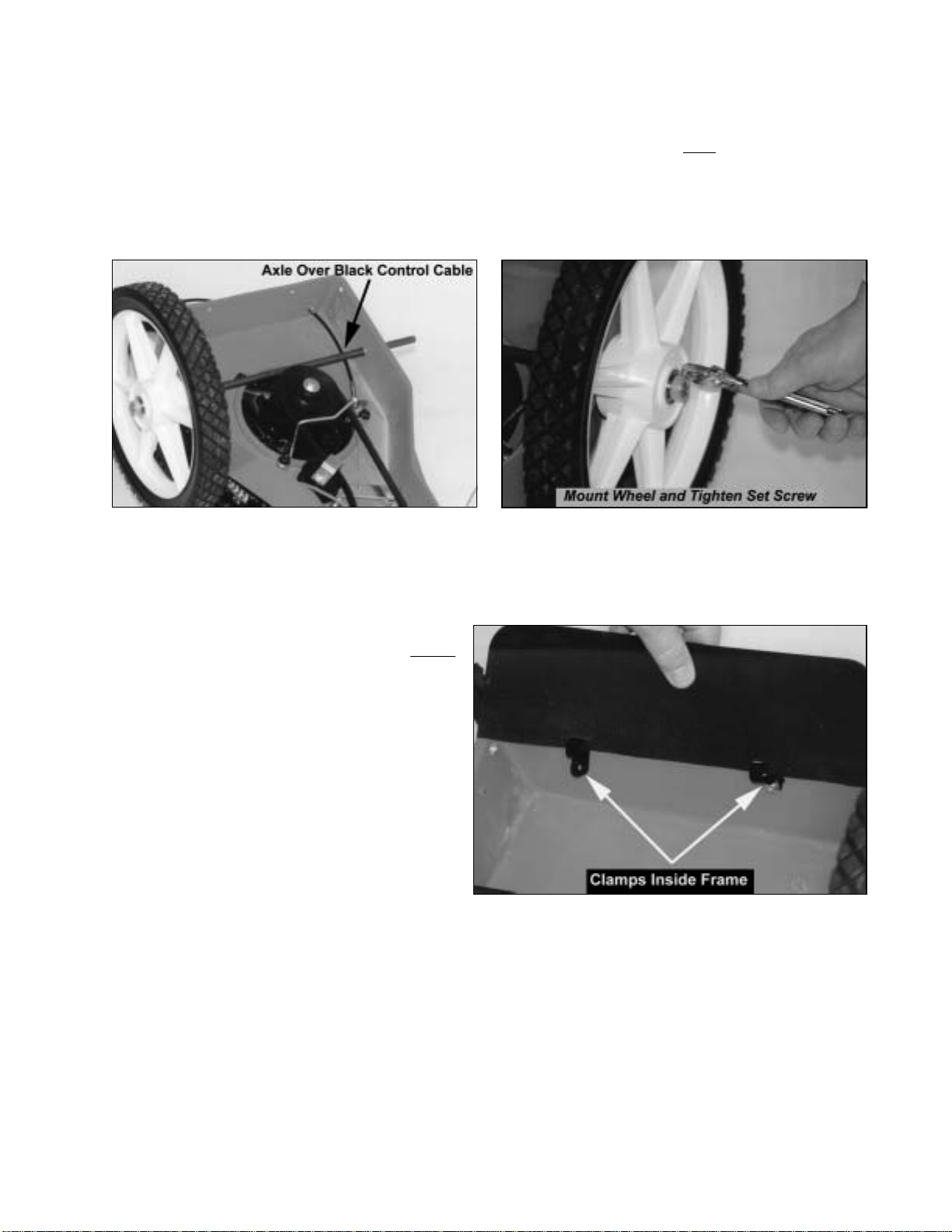
4. Insert the axle through the hole in the bushing in the side of the housing (Figure 5). Push the
axle through both axle holes in the frame (Figure 5). Be sure the axle is over the black control
cable.
5. Mount the other wheel with the open portion of the hub facing in toward the frame. Mount the
retaining ring so it is flush with the axle and tighten the set screw (Figure 6).
Step 2: Attach the Rubber Stone Guard
1. Mount the two black clamps on the rubber
stone guard. With the clamp on the inside
of the frame, insert the screws from the
outside of the frame facing in, add the
lock nuts and tighten them (Figure 7).
Step 3: Set the Machine Upright
Note: Be careful not to kink, twist or stretch
the control cables.
1. Remove the front end of the Styrofoam
packing.
2. Stand at one side of the machine, hold one
wheel with one hand, and the nose of the
machine with the other. Lift the front-end
of the machine up and over until the Mow-Ball™Support is resting on the ground and the
machine is upright (most of the weight is on the wheels during this maneuver).
3. Being careful of the cables, bring the upper handlebar up and over the front end of the machine.
Let it rest there.
Caution: DO NOT add gas or oil to the engine at this time.
Figure 5 Figure 6
Figure 7
DR®TRIMMER/MOWER™Assembly & Operating Instructions 7
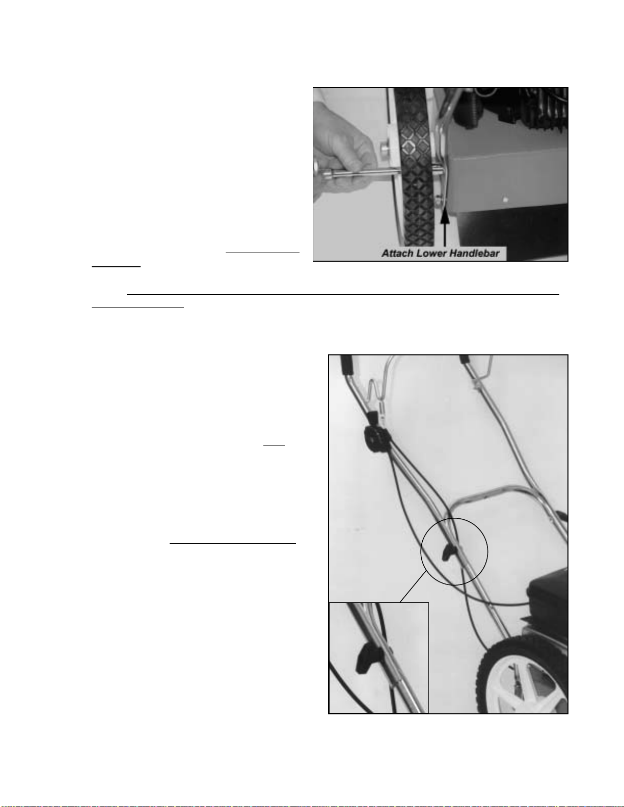
Step 4: Install the Handlebars
A) Lower Handlebar
Note: There are 2 U-bolts, 4 washers, and 4
lock nuts in your parts bag that will be needed
for the lower handlebar assembly.
1. With the control cables on the inside of the
handlebars, position the lower handlebar
over the bolt holes in the trimmer frame
(Figure 8).
2. Mount one of the U-bolts through the hole
in the frame and handlebar from the inside
facing out (Figure 8). Repeat on the other
side.
Note: Make sure the black control cable that runs along the right underside of the frame is not
beneath the U-bolt.
3. Mount the washers and nuts and snug them on both sides—don't tighten them yet. Position the
lower handlebar so the bolts are in the middle of the slotted notch on each side. This is the
average height needed by most users. Tighten
the nuts securely. After you install the upper
handlebar you'll be able to judge whether you
need to adjust the height.
B) Upper Handlebar
1. Making sure the control cables are over the
lower handlebar, position the upper handlebar
outside the lower handlebar (Figure 9). The
ends of the upper handlebar are cupped half-
circles and fit on the outside of the lower
handlebar (inset). With the holes aligned,
insert one of the two round-headed 1-1/2"
handlebar bolts from the inside facing out.
2. Secure the bolt with one of the large black
handlebar knobs on the outside of the
handlebar. Repeat on the opposite side.
The height of the handlebar depends on many
factors for each individual. However, it is crucial
to find a height that allows the Mow-Ball™
Support to glide along the ground and remain
balanced without the operator having to push
down or pull up on the handlebars. At the proper
height, your hands should rest at a comfortable
level and the front end should roll easily on the
Mow-Ball™Support.
Figure 8
Figure 9
8DR®TRIMMER/MOWER™Assembly & Operating Instructions
To adjust the height of the handlebars, loosen the lock nuts on the U-bolts. Push the handlebars
forward for more height, backward for less. Then tighten the nuts securely.
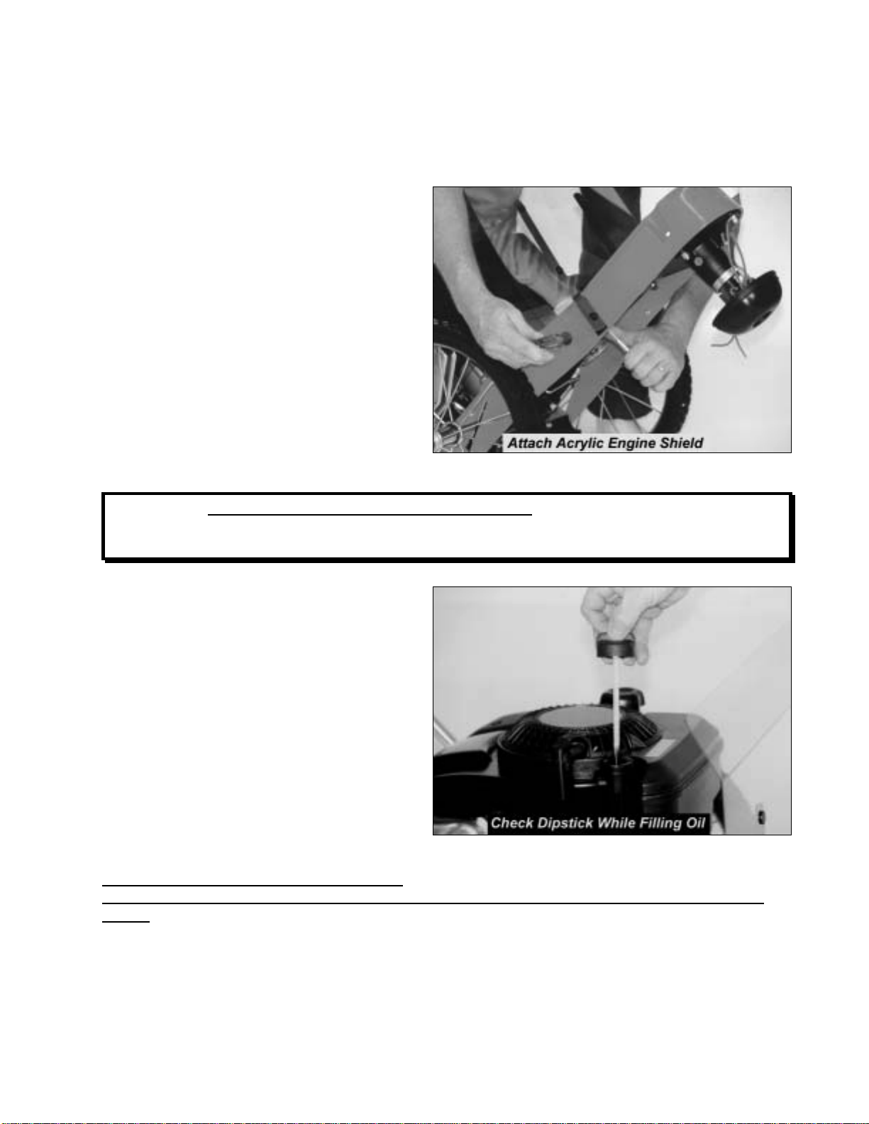
Step 5: Attach the Acrylic Engine Shield
Use the four remaining sets of 5/8" long bolts
and lock nuts to attach the acrylic engine
shield.
We have found it's easiest to tip the machine
back on its handlebars in order to reach the
underside.
1. Position the shield on the frame in front of
the engine (Figure 10) with the bend at
the top facing the handlebars.
2. Insert the bolts from the outside facing in,
screw on the nuts and tighten (Figure 10).
Step 6: Add Oil and Gas
WARNING!: You must add oil before starting the engine. There may be 1 to 2 ounces of
oil left in your machine from factory testing, but you still need to fill the reservoir. Check
the dipstick while adding oil to avoid over filling.
Please refer to your Engine Manufacturer's
Owner's Manual and put the recommended
amount of engine oil in the oil fill. Use
SAE30 High Detergent oil. Fill the oil to the
amount indicated on the dipstick. Do not
overfill (Figure 11).
Reminder: To avoid confusion, we
recommend leaving the caps on the fuel and
oil fills until you are ready to pour either
gasoline or oil into the correct fill.
Fill the gas tank to within 1/4 inch of the top
with fresh, unleaded gas. (See your engine
manual for more detailed fuel
recommendations.)
Caution: Once you have added the oil and
gas, avoid tipping the trimmer back on its handlebars. Doing so will cause the cylinder to fill
with oil. If you need to reach the underside of the trimmer, drain the oil and gas first, or set the
machine up on a workbench.
Figure 10
Figure 11

DR®TRIMMER/MOWER™Assembly & Operating Instructions 9
Step 9: Connect the Battery Wires (Electric-Starting models only)
To prevent the battery from discharging
during shipment, all electric-starting
trimmers are shipped with the black, negative
battery wire disconnected. Connect the two
black wires by pushing the plastic ends
together (Figure 12). See the red wires for
comparison. The wires are located on the left
front side when standing in the operator's
position.
Figure 12

10 DR®TRIMMER/MOWER™Assembly & Operating Instructions
Controls & Features
Please Note: Manual-Starting Model shown.
Figure 13

DR®TRIMMER/MOWER™Assembly & Operating Instructions 11
Starting & Operating
Please Note: Manual-Starting model is pictured below.
Electric-Starting
1. Push the throttle control lever on the right side of the handlebar (Figure 13) all the way forward
to the START position.
2. Prime the engine. Make sure you completely cover the air hole on the primer bulb (Figure 14).
Push the black primer bulb in and hold it for three seconds, then completely release it for three
seconds (making sure you uncover the air hole). Repeat three to four more times.
Note: Priming is usually unnecessary when restarting a warm engine. In cool weather priming
may need to be repeated.
3. Turn the key to the START position until the engine starts, then release. The key will snap back
to the RUN position (Figure 14).
Manual-Starting
Can be used with both Manual- and Electric-Starting models.
1. Push the throttle control lever on the right side of the handlebar (Figure 13) all the way forward
to the START position.
2. Prime the engine. Make sure you completely cover the air hole on the primer bulb (Figure 14).
Push the black primer bulb in and hold it for three seconds, then completely release it for three
seconds (making sure you uncover the air
hole). Repeat three to four more times.
Note: Priming is usually unnecessary
when restarting a warm engine. In cool
weather priming may need to be
repeated.
3. Grasp the recoil starter handle (Figure
13), and slowly pull until resistance is felt.
Next, pull the cord rapidly to overcome
compression, prevent a kickback and start
the engine. One or two pulls usually starts
the engine, but it may be necessary to
repeat the priming. Figure 14
WARNING!
THIS MACHINE IS SHIPPED WITHOUT OIL! TRACES OF OIL MAY BE LEFT IN THE
RESERVOIR FROM FACTORY TESTING, BUT YOU MUST ADD THE
RECOMMENDED AMOUNT OF OIL BEFORE STARTING THE ENGINE.

12 DR®TRIMMER/MOWER™Assembly & Operating Instructions
Stopping the Engine
Move the throttle lever back to the STOP position (Figure 13). Note that on Electric-Starting
Models the key does not stop the engine. The key has a pressure lock that prevents it from vibrating
loose during operation. If you wish to remove the key, push it in and then quickly and firmly pull it
out. If the key is difficult to remove, spray FLUID FILM®or a comparable lubricant into the key
hole.
Engaging the Trimmer Head
Bring the trimmer head control bar (Figure 13) toward you and grip it together with the handlebar.
Keep holding the trimmer head control bar to the handlebar. The cutting cords will now be rotating
and will continue to rotate until you release the trimmer head control bar.
Stopping the Cords from Spinning
Release the trimmer head control bar from the handlebar. The trimmer head will stop spinning while
the engine continues to run.
If the cutting cords keep spinning after the trimmer head control bar is released, you may need to
adjust the trimmer control cable. (See page 27.)

DR®TRIMMER/MOWER™Assembly & Operating Instructions 13
Cutting Cords
WARNING: Turn the engine off when
installing or changing cutting cords.
Two thicknesses of cutting cord ship with your
DR®TRIMMER/MOWER™: Heavy-duty (130
mil) Orange and Extra Heavy-duty (155 mil)
Green. Figure 15 shows how the cords are
installed at the factory. Notice how the cords
are installed before you replace them.
Note: Before trimming, always spin new cords
for a few seconds so they pull tight and set.
Because conditions and vegetation vary so
much, experiment with various combinations
of cord weight and installation methods in
order to discover what works best for your
particular mowing and trimming situations.
Here are a couple of things to keep in mind:
·If you buy cutting cord in rolls, cut it in 21" lengths.
·Store your cutting cord in a plastic bag with a damp sponge or rag. This will help retain moisture
and keep the cords more pliable.
Please see page 15 for additional cutting cord installation methods and tips for getting the best
performance from your cutting cord.
Figure 15

14 DR®TRIMMER/MOWER™Assembly & Operating Instructions
Trimming and Mowing Methods
Note: The cutting cords cut one to two inches
outside of the wheel width.
Many owners like to mow easy, open areas
with their regular riding or walk-behind
mower, then finish trimming all the odd and
hard-to-reach spots with the DR®
TRIMMER/MOWER™.
The DR®TRIMMER/MOWER™discharges
cut material to the right. Always try to cut
and trim with the uncut tall grass or weeds at
the left (Figure 16).
FSuggestion: For the neatest
appearance, do your trimming first,
discharging clippings away from borders and shrubs, then do your mowing.
Obstacles
·Always check your work area before trimming and remove any debris that might tangle or
damage the machine.
·If you do run into debris and the trimmer gets tangled, turn off the engine and disconnect the
spark plug wire before attempting to untangle it.
·DO NOT run the machine over gravel driveways or over loose stones or mulches with the
trimmer head spinning. The machine's power can easily throw stones, sticks and other debris at
great velocity, which could cause personal injury or property damage.
Mow-Ball™Support
Allow the front end of the machine to rest lightly on the Mow-Ball™Support as you are trimming.
The Mow-Ball™Support should glide on the ground as you maneuver the machine.
In order to achieve the best and smoothest cut, do not lift up on the handlebar while operating your
DR®TRIMMER/MOWER™. Lifting the handlebar causes weight to be forced down on the Mow-
Ball™Support. This uses more energy, slows down the cutting, and produces a less than satisfactory
cut. Ideally, the Mow-Ball™Support should rest lightly on the ground while the wheels balance
most of the weight of the machine. If needed, use slight downward pressure on the handlebar to
prevent the Mow-Ball™Support from digging into the ground.
Cutting Cords
The best trimming performance will usually come from using the smallest diameter cord that is still
capable of cutting the material at hand, combined with the fastest engine speed. When more power
is needed for thicker growth such as berry canes, brambles, thistles or ragweed, you may want to use
the Extra Heavy-Duty Green (155 mil) cord in combination with the highest engine speed.
Figure 16
Table of contents
Other Country Home Products Lawn Mower manuals


