Creative controls LogiTouch User manual
Ver.2.1
Up to 18 Functions
Wireless Handset Controls
The Control Unit is powered by the ignition
and will only operate when the ignition is on.
The Transmitter is battery powered and only
operates when a button is pressed.
The maximum operating range in free air
is approximately 20 yards. each one has its
own unique ID code so there is no danger of
operating another vehicle accidentally.
The cars existing controls are unaffected by
the transmitter signal and will operate as
normal. For the control to work correctly, the
car's controls should be set to turn indicators
off and lights on low beam.
3500
Installation Manual
*patent (or pending)
INSTALLATION GUIDE
is approximately 20 yards. each one has its
own unique ID code so there is no danger of
operating another vehicle accidentally.
The cars existing controls are unaffected by
the transmitter signal and will operate as
normal. For the control to work correctly, the
car's controls should be set to turn indicators
off and lights on low beam.

LogiTouch Installation & Setup Instructions, Ver. 2008
LOGITOUCH INSTALLATION INSTRUCTIONS – 18 FUNCTIONS
We can supply wiring diagrams for over 200 different vehicles, inquire for availability.
Those that are not available can be developed with a one – two week lead time.
Logitouch systems are transferable. A new hook-up sheet will be required unless it is transferred to an
identical car, and can be obtained from cci.
We can also supply technical support for any problems during installation.
Vital equipment you will need for us to help you is a volt meter or at least a test light.
The Logitouch system is sent pre-set with the recommended mode setup based on the vehicles’ options and
wiring for which it was ordered.
The installer can change modes when desired and add optional functions to unused relays (within limits) to
suit the users needs.
Quick start guide for people who have done it before:
1. Strip down vehicle cowling and find a suitable place to locate the decoder. Note that you no
longer have a receiver box to install up the side of the door pillar trim.
2. Using the specific wiring included (included in the kit when it was ordered)
3. Connect the 3 power wires first - black, orange & red. Make sure it beeps three times when
ignition is turned on. This is also a handy diagnostic to warn of intermittent connection.
4. Initialize the transmitter Decoder Setup. Nothing will work until you do this.
5. Connect the decoder relays one set at a time, working down the page. Check functions one at a
time as you wire them so it is easier to trace problems.
6. Secure the decoder in position; note the holes on the sides of the case for easy attachment with
cable ties or even screws if you are lucky enough to find a flat surface.
7. Reassemble the car. PLEASE READ CLAMP FITTING INSTRUCTIONS CAREFULLY FIRST -
Fit the transmitter on the wheel, note the clamp faces MUST meet - as shown on page 2 & 3
below.
8. Recheck that all functions are working on the LogiTouch AND the car correctly. Note that some
functions may not work. See the specific wiring diagrams supplied, which may save you lots of time
trying to get the hazards to work for example.
This set of instructions is for the installer.
LogiTouch Installation & Setup Instructions, Ver. 2008
Pg. 1
Overview:
The new RKS100 is a remote keypad system that operates the vehicle secondary controls using a wireless (2.4Ghz
radio link) system. It has been designed to offer the most flexibility available. It is one standard, universal kit that can
be installed a number of different ways. Some components will not be needed for some installations. The transmitter
keypad can be used on its own or fitted onto the steering wheel using the clamp and steering ball assembly. The
decoder relay box is designed to cope with as many different vehicle designs that we are currently aware of.
Please note it does not need to have a receiver box, as this is now built in the decoder.
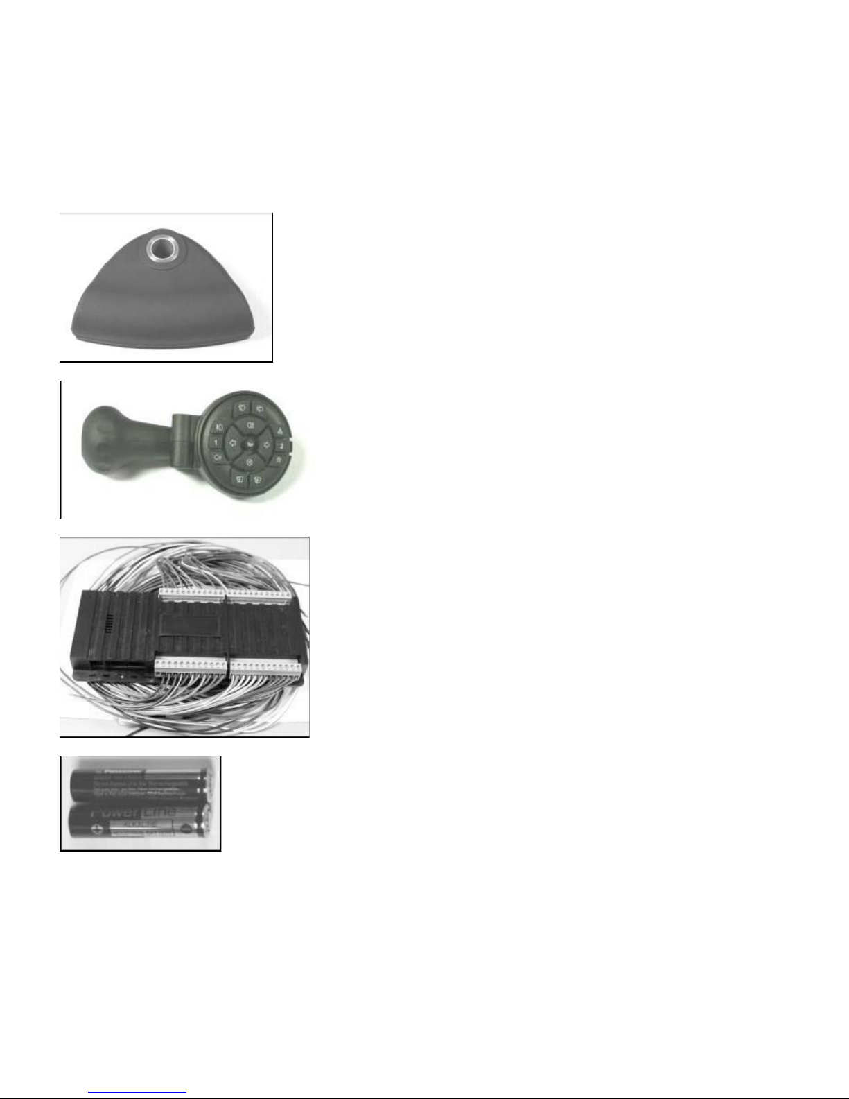
The kit consists of:
1 x steering wheel clamp
1 x transmitter steering ball assembly with RKS100 keypad
1 x RKS100 decoder relay box
2 x AAA Alkaline batteries
3 x 13mm screws 4 for mounting transmitter to a mounting plate
1 x customer information
1 x wiring instructions for particular vehicle
1 x interface box (only if required for particular vehicle in the wiring instructions above)
1 x additional parts (only if required for particular vehicle in the wiring instructions above)
LogiTouch Installation & Setup Instructions, Ver. 2008
Pg. 2
Transmitter Keypad:
The transmitter keypad is battery powered, and the batteries will last 2-3 years with average use. The maximum operating range in free air is
approximately 20 yards. Each one has its own unique ID code so there is no danger of operating another vehicle accidentally. There is a low battery
indicator which also indicates if the transmitter is being received by the relay box. If it goes out the instant a pressed button is released, it is working.
If it stays on for about half a second, then the transmitter is not in communication with the relay box.
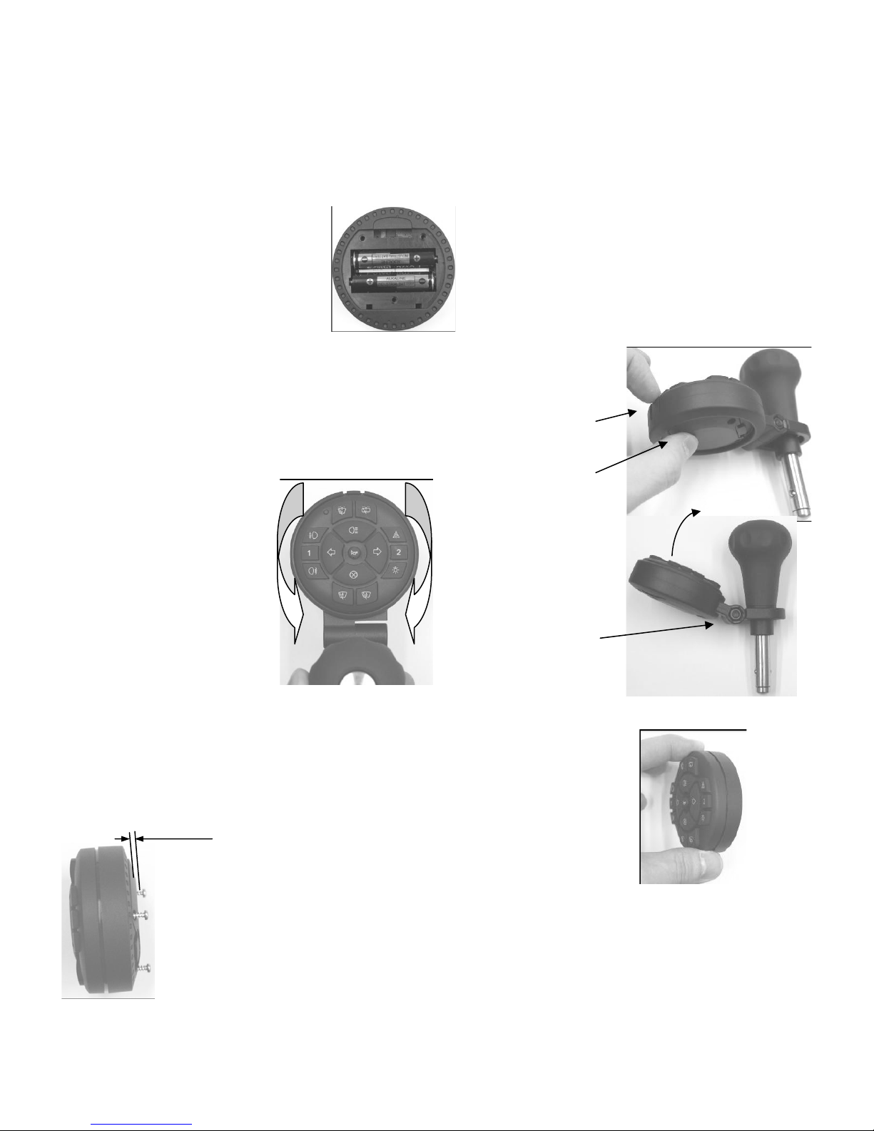
Battery installation:
Use alkaline AAA batteries ONLY, not rechargeable batteries or any other type.
The batteries are installed as shown:
Refit the 3 battery cover screws.
Methods of use:
1. Attached to the steering wheel using the transmitter ball assembly & clamp
(supplied in kit):
The transmitter can be adjusted at any rotary angle required by the user. The keypad is supplied pushed into
the mounting ring. CAREFULLY remove it by pushing up the keypad and pulling on the locking tab:
2. Used on its own:
3 Attached to a flat surface:
Carefully pull on tab
to release transmitter
Push here
Locate the keypad in the ring at the
required angle.
Note it may need to rotate slightly to
line up with the locking pins
underneath.
Push into locking ring and make
sure it is securely locked in position.
The angle of the keypad
face can also be adjusted.
Undo the locking bolt and
adjust as required, then
retighten.
The keypad can be hand-held and used anywhere in the vehicle. It does not need to be
in line of sight with the decoder or any receiver and can be used anywhere.
The keypad can be fixed to a plate by using the longer screws supplied in the kit.
These are intended for a mounting plate .039 - 118” thick.
Do not use any screws other than the ones supplied.
Do not use the longer screws to hold the battery cover in place, otherwise, the transmitter will be damaged.
Alternatively, Velcro or double sided tape may be used.
For a mounting plate of
.039 - 118” (20-12Ga.)
thickness only.
LogiTouch Installation & Setup Instructions, Ver. 2008
Pg. 3
Steering wheel clamp & steering ball assembly and use:
The steering knob assembly does not need any oil or grease. It has a resistance element built into it which needs the clamps to be installed as
follows for it to work correctly. The clamp is designed to be fitted to a wide range of wheels. By using the inserts different sizes can be
accommodated. The rubber inserts are designed to act as spacers and to be cut to allow for any bulges in the steering wheel.
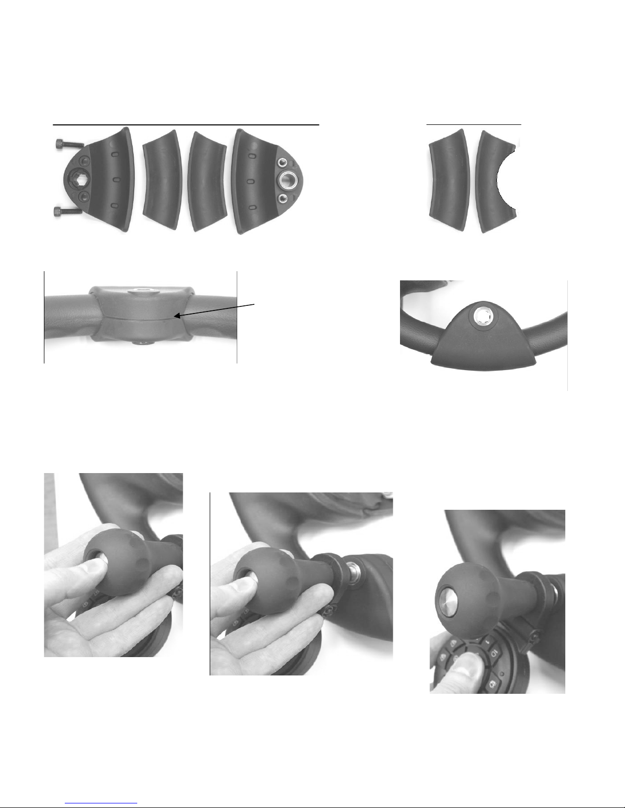
Clamp components:
Clamp assembly: Note that the clamp when assembled is designed to be fitted with both faces meeting.
Remove or add the rubber inserts to accomplish this.
To remove the steering ball from the clamp, push the button in and at the same time pull the steering ball out of the clamp.
Bolts, lower plate, rubber insert, rubber insert, top plate (facing driver)
Correctly attached clamp with no
gap between top and bottom plates.
Driver’s view of correctly attached
clamp with bolts and resistance
part hidden.
To fit the steering ball assembly in the
clamp, push the steering ball release
button in: Then push it into the steering wheel clamp:
Then push it in firmly until the release
button pops out:
Rubber inserts can be cut as
needed to allow for wheel shape.
LogiTouch Installation & Setup Instructions, Ver. 2008
Pg. 4
Decoder relay box:
Overview:
The decoder has a built in transceiver which communicates with the transmitter. It is designed so any set up procedures can be carried out without
any extra equipment, with the transmitter acting as a control interface to change any settings. It is designed to directly drive any of the usual
secondary controls on a car (turns, lights etc) with a minimum of extra components. Note the decoder will sound 3 beeps as a power up indicator.
Decoder Relay Specifications:
Relay contacts voltage: 30V (so it will operate 24v vehicles)
NO contacts: 30A continuous
NC contacts: 20A continuous
Cables (all): 16A (see 2, 3)
Range: 20 yards (open air)
Maximum supply current: 2A (see 1, internal power for unit only)
Maximum supply Voltage: 15V (see 1)
Standby Current: Minimal
1. Total maximum applied to decoder Orange (constant +12v) and Red (switched +12v) with black as 0v for internal electronics
2. Continuous in free air at room temperature, if in a bundle capacity will be reduced. Higher ambient temperature will reduce this too.
3. In practice these cables will directly carry all standard production vehicles headlights, wiper, washer, etc. current. The cables are thicker than
those often used in cars.
Decoder relay box installation, setup & wiring:
Location: Find a suitable location for the decoder unit to be fixed securely behind the dashboard - check all cables are tied safely out of reach of the
driver’s feet, steering and pedal mechanisms. Remove the steering column shrouds and run the cables from the decoder box to the switch clusters
behind the steering wheel. Wiring installation instructions for most commonly used cars can be supplied by CCI on request. Below are general wiring
details for the decoder box relays including some typical configurations. These will obviously vary between vehicles. Unused cable looms can be
removed if required.
Decoder power: The Red wire and Orange wire are typically wired to the cars ignition switch for the switched and constant +12v so the unit is
switched on only with the cars ignition. Note that the majority of the power (2A maximum) is taken by the Red wire; the Orange wire is a maximum of
30mA. The 0v (Black) wire should be a suitable permanent 0V point, usually the chassis. The constant +12v supply is needed so the hazards, horn
and lights will continue to function if the ignition is off.
Decoder Setup including transmitter initialization:
The decoder will need to be set up to recognize the transmitter before use. It won’t work until this is done.
With the decoder power, including BOTH constant and ignition switched +12v connected (black, red & orange):
To initialize the transmitter & decoder:
1. Press dimmer and cancel, simultaneously, transmitter sends an initialize request signal.
2. Switch the decoder on (the decoder will sound 3 beeps), wait 10 seconds.
3. Release the switches. Decoder will say “transmitter identified”.
4. Decoder can recognize up to 5 transmitters. Any programmed after 5, will bump off the earliest previously programmed ones.
5. If you try to set up a transmitter that has been already, the decoder will say ”transmitter already set up”, and ignore it.
The decoder will in some vehicles need different methods of relay operation. For example, the high beam on some vehicles may instead be
momentary. The mode of each relay may need to be changed from the default mode to work with different vehicles. Don’t try this unless you are
familiar with this procedure.
To enter setup mode with an initialized decoder:
1. Press left turn and right turn, simultaneously, transmitter sends an initialize request signal.
2. Switch the ignition on (the decoder will sound 3 beeps), wait 10 seconds.
3. Release the switches and the decoder will say “setup mode”.
4. For details of the different setup modes and what they do, see below (note - only in full installation details).
5. To exit setup mode, switch off ignition or select mode #20.
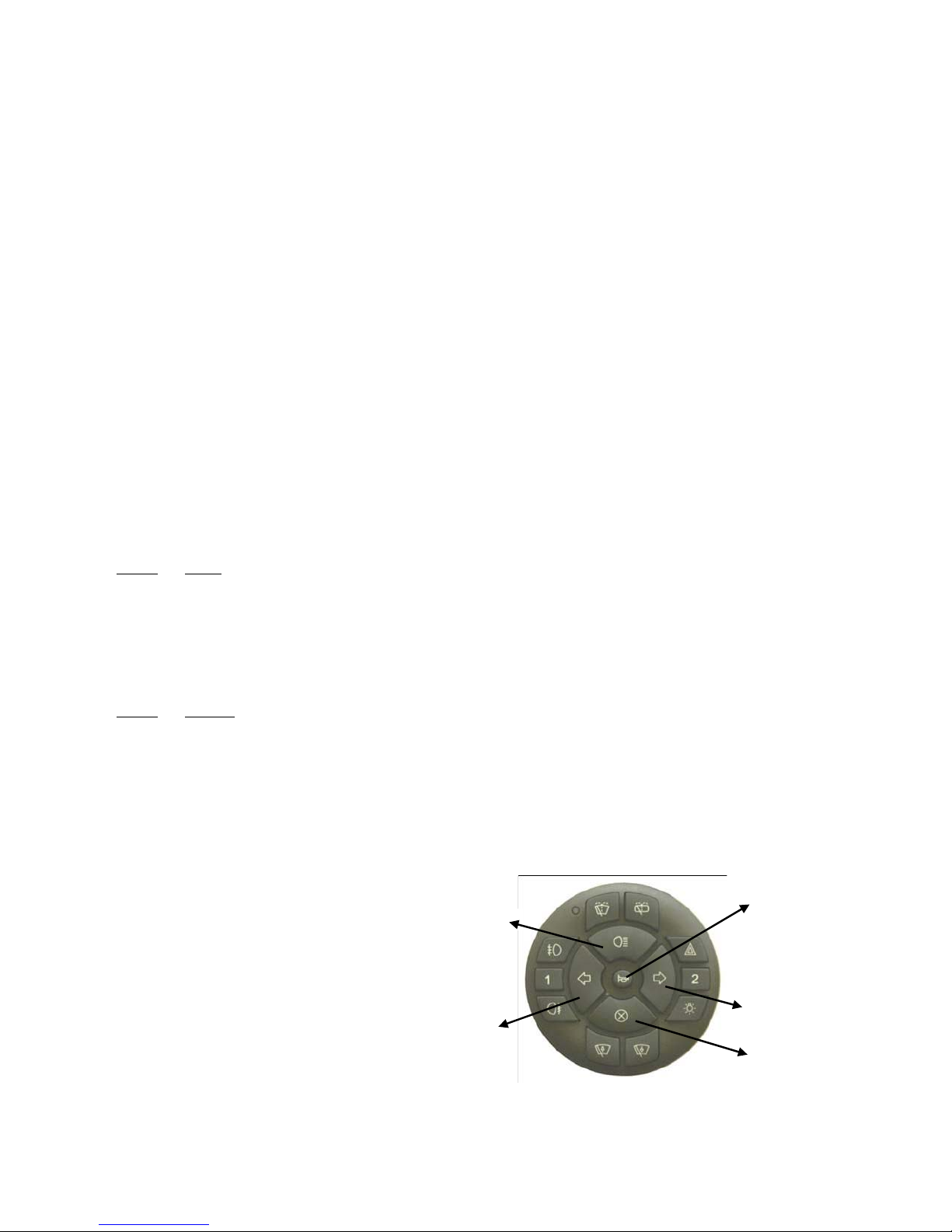
Setup modes and operation: (for details of the setup modes and what they do, see below) Setup mode has a menu type functionality, with the
middle five buttons selecting and changing the different modes. Main beam is “up menu” and cancel is “down menu”. By going up or down the menu,
you can select the different relay functions to preset. The turn arrows increase or decrease the mode number of each function. Horn acts as
“confirm” or select. If horn is not pressed, the mode for that function is not changed; it is left at default or its already selected setting.
Once in setup mode, the menu starts at turn indicators. Every time new functions are selected by the main beam (up) or cancel (down), the unit
responds with Function & Mode number, i.e. “Turn indicator mode four”.
It will respond with the function and mode selection list in this order:
*Defaults 4 sets all modes back to mode 1
** Clear transmitter list - wipes any recognized transmitters from memory, including the one used to select this. Simply reinitialize it as above.
*** Exit setup - either select this to get into normal user mode, or turn off ignition after completion.
New Function: Keypad Illumination: (for new keypads, made 2008 on only)
Press indicator cancel button for 5sec., until LED flickers, to turn illumination on/off. Illumination will turn off 20–30min.after last button press to save battery.
1. Indicator mode
2. Timer mode
3. Hazards mode
4. relay mode
5. Main mode
6. Horn mode
7. Front wipers mode
8. Front washer mode
9. Rear wash mode
10. Headlights mode
11. Rear fog mode
12. Front fog mode
13. Extra function 1 mode
14. Extra function 2 mode
15. Spare 1 mode
16. Spare 2 mode
17. Spare 3 mode
18. Defaults*
19. Clear transmitter list**
20. Exit setup***
Up Function List
Down Function List
Decrease
Number of Mode
Increase
Number of Mode
Confirm
Mode Selection
LogiTouch Installation & Setup Instructions, Ver. 2008
Pg. 5
Decoder relay box internal modes function detail:
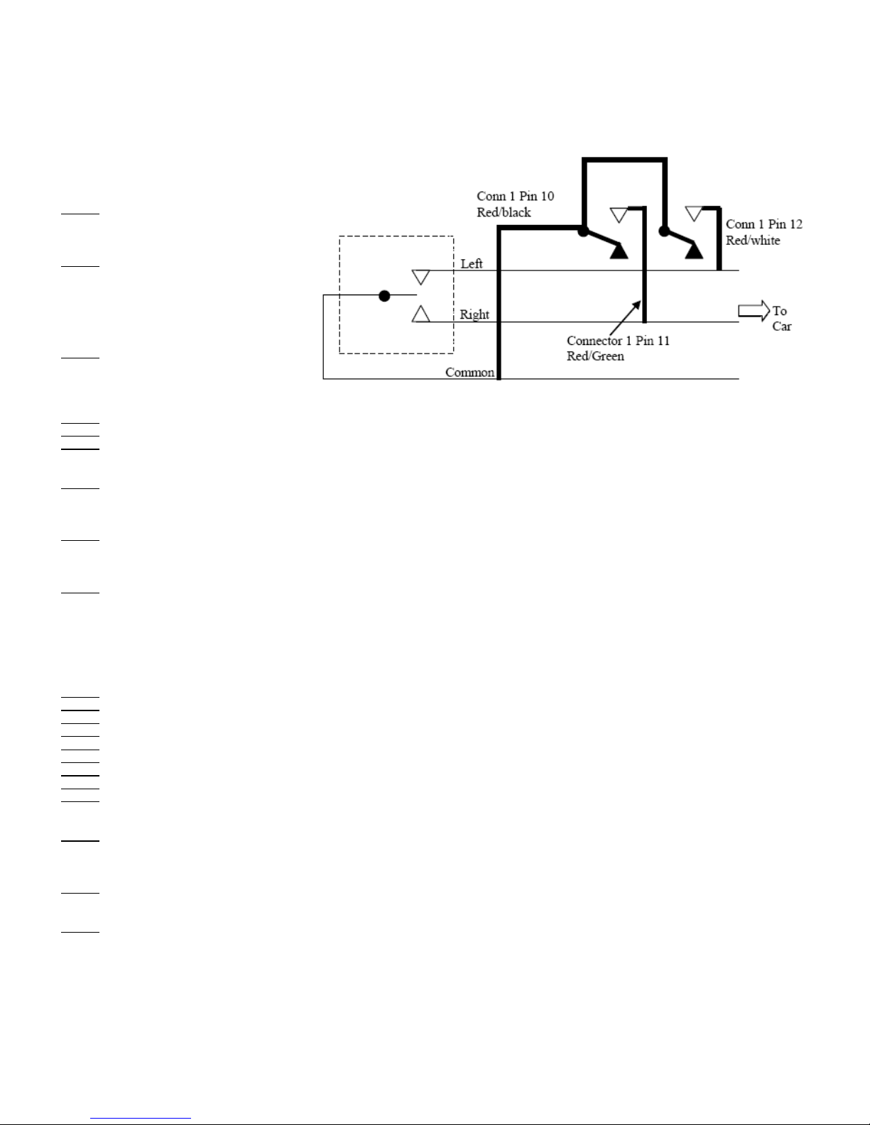
Turn Indicators and hazards wiring: The first three turn indicator wires are intended to be wired in parallel with the vehicle indicator switches on
vehicles that have independent turn lamps. The additional four wires are for domestic style turn indicators that are shared with the brake lamps.
Description of indicator functions:
A. The indicators can operate standard indicator circuits as fitted to many European and Japanese vehicles:
B. Example Circuit:
C. Turn Indicator modes:
Mode 1 (Default)
Turn Indicators latching on and off, pressing
either direction turns them on only, press
cancel to turn them off.
Mode 2
a. Turn Indicators latching on and off, pressing
either direction turns them on only, press
cancel to turn them off.
b. If either direction is left on for more than
(preset time) seconds, a half second tone is
generated from the speaker as a warning.
Mode 3
a. Turn Indicators latching on and off, pressing
either indicator turns them on only, press
cancel to turn them off.
b. If either indicator is left on for more than (preset time) seconds, they are turned off automatically.
Mode 4 (not implemented yet)
Mode 5 (not implemented yet)
Mode 6
a. Turn Indicators are latched on and off by pressing the appropriate arrow, cancel has no effect.
b. Also, if decoder is in standby (ignition off), selecting either direction turns the hazards on or off.
Mode 7 (left front first, then left rear 0.5 sec later, same for right turn indicators)
a. Momentary function; if left is pressed, the front left operates first. This stays on while the rear left comes on 0.5 seconds later.
b. On release of the switch, both turn off. (for new Astra, BMW 1 series etc. which has a 2 step indicator, first step is for 3 short flashes, second is for
constant on until cancelled electronically on car or a 1 step right indicator). Same as above for the right turn indicator.
Mode 8 (as mode 7 above but left front indicator and left rear indicator are never on at the same time)
a. Momentary function; if left is pressed, the front left operates first. This goes off just before the rear left comes on 0.5 seconds later.
b. On release of the switch, both turn off. (For new Astra etc which has a 2 step indicator, first step is for 3 short flashes, second is for constant on
until cancelled electronically on car or a 1 step right indicator). Same as above for the right hand indicator.
Mode 9 (Extra activation code) (left front first, then left rear 0.5 sec later, same for right indicators)
a. Momentary function; if left is pressed, the front left operates first. This stays on while the rear left comes on 0.5 seconds later.
b. On release of the switch, both turn off.
Note: left rear left comes on 0.5 sec after operation of EITHER left or right indicator. (for new Astra BMW 1 series etc which has a 2 step indicator,
first step is for 3 short flashes, second is for constant on until cancelled electronically on car or a 1 step right indicator). Repeat above for the right
hand indicator.
D. Timer, for Turn Indicator cancel or warning buzzer time (preset time):
Mode 1 (Default) Turn Indicators time is 5 seconds
Mode 2 Turn Indicators time is 10 seconds
Mode 3 Turn Indicators time is 15 seconds
Mode 4 Turn Indicators time is 20 seconds
Mode 5 Turn Indicators time is 25 seconds
Mode 6 Turn Indicators time is 30 seconds
Mode 7 Turn Indicators time is 35 seconds
Mode 8 Turn Indicators time is 40 seconds
Mode 9 Turn Indicators time is 45 seconds
E. Hazards: various functions: Note that Hazards are a “soft” output that can be allocated if needed to any of the three spare relays.
Mode 1 (Default) Turn Indicators & hazards - latching
a. Latching function; Hazards operate both turn indicators when pressed; press to turn on or off both indicators. (DEFAULT)
b. If turn indicators are on or off, pressing Hazards turns both on; pressing again turns them both off.
c. Pressing either direction or cancel overrides the hazards.
Mode 2 Hazards only - Latching
a. Hazards does not affect turn indicators at all when pressed.
b. Hazards output is latching, it toggles on or off if the hazards button is pressed.
Mode 3 Hazards only - Momentary
a. Hazards does not operate indicators when pressed, has no effect on indicators at all.
b. Hazards output is momentary, it comes on only while the hazards button is pressed.
Car turn
in
d
icato
r
switch
Fig. 1 Turn Indicators – Import
style (brake independent)
LogiTouch Installation & Setup Instructions, Ver. 2008
Pg. 6
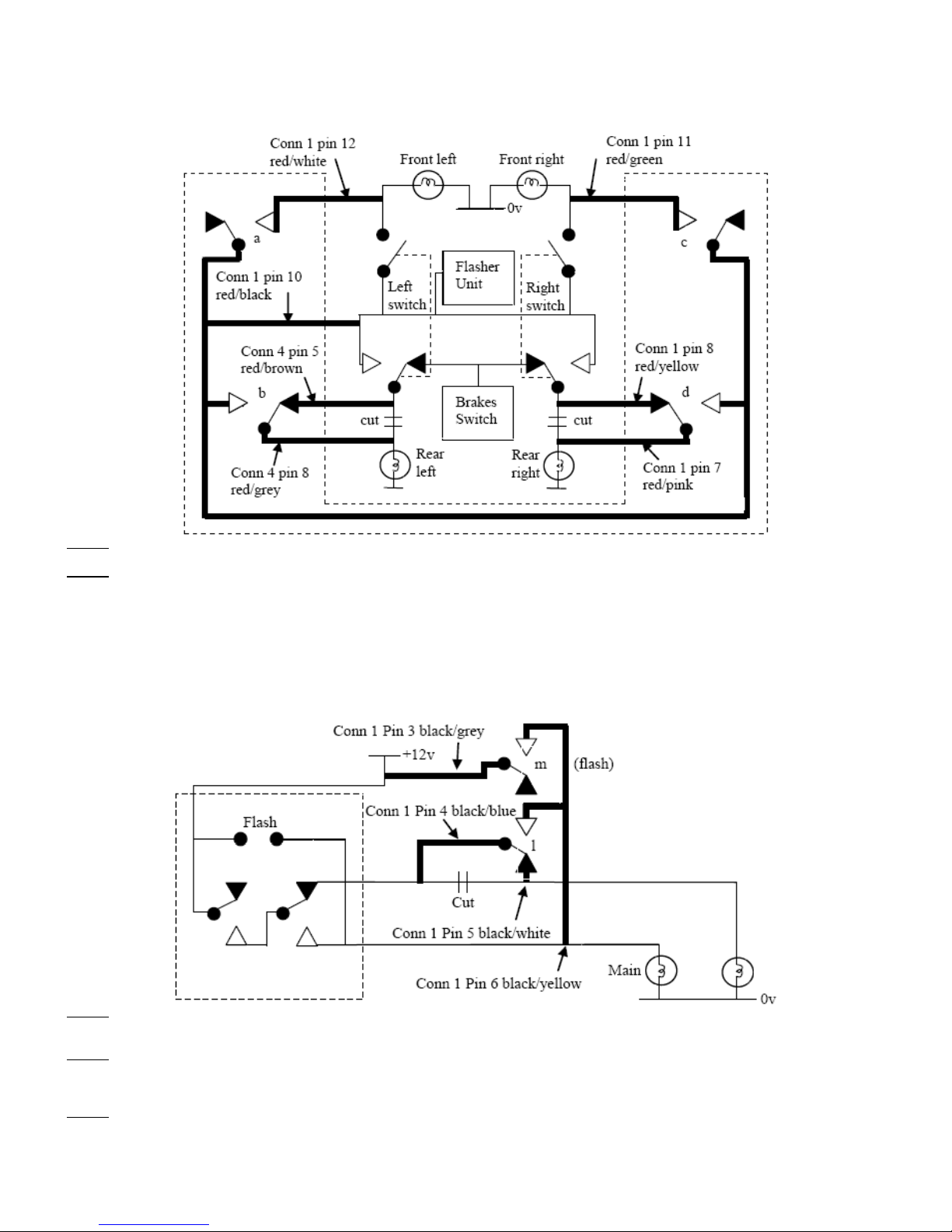
F. Relay (Four) Turn Indicators Mode (many domestic vehicles)
a. The decoder can be set to operate the style of turn indicators that share a rear lamp for brake and turn. This will directly drive the car with no
additional components or relays.
b. Example Circuit:
Mode 1 (Default) Front Turn Indicators only.
Turn Indicators front left and front right only are used, rear left & rear right are not used (unless specified, as in turn indicator modes 7 & 8).
Mode 2 Front and rear indicators are used.
Indicators front left and right are used at the same time as rear left & right.
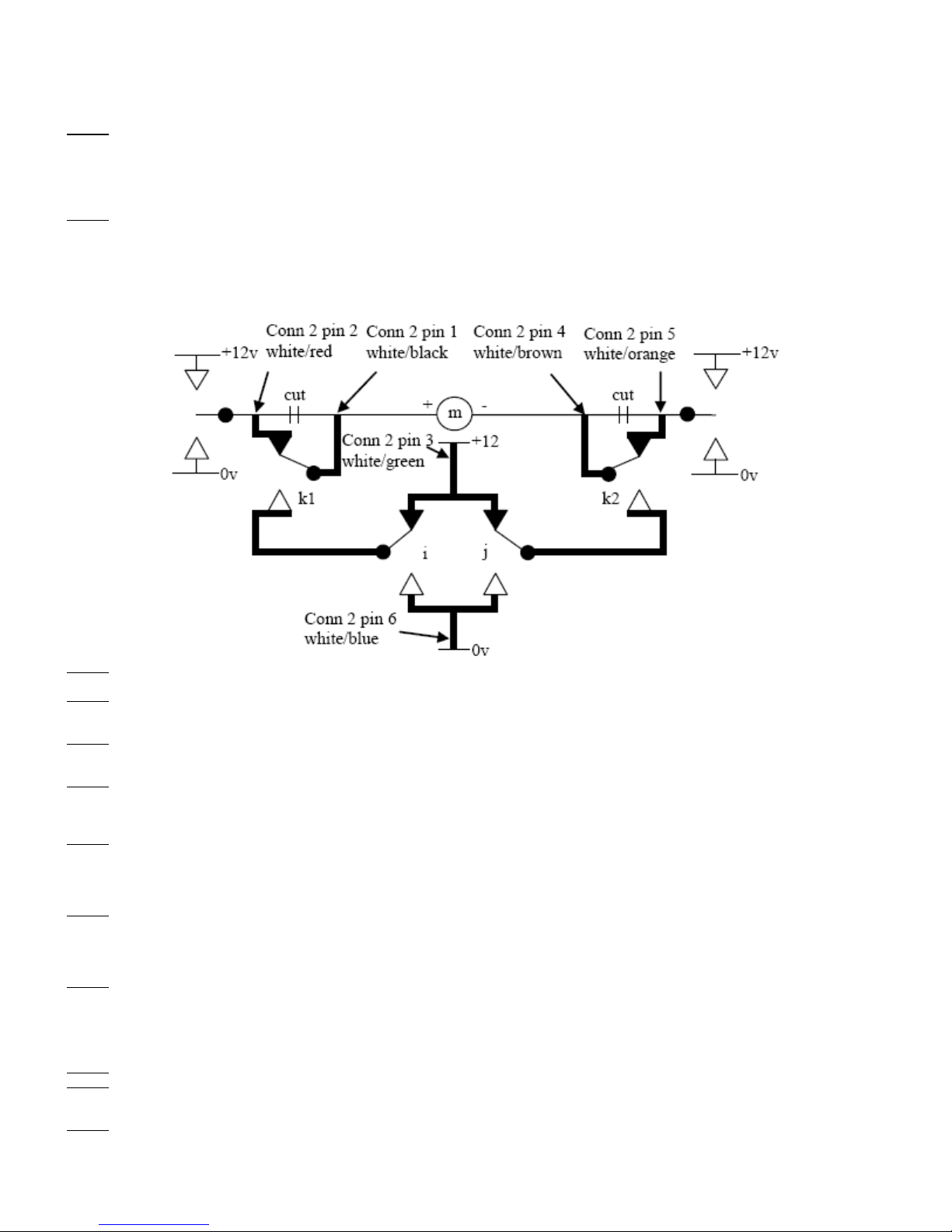
5. Dim/Main/Flash for Headlights. Note: there are 2 relay outputs, one for dim/main beam, and one for flash.
a. Headlight Dim/main: This is wired so the existing headlights switch operation remains functional. The decoder box relay switches the power away
from the low beam to the main beam when operated. When the decoder headlight relay is off, the vehicles headlight switch will operate as normal.
This may vary depending on the car - if the dim stays on when the main beam is selected, for example on some BMW models, then the relay just
turns on the main beam.
b. Flash: This typically supplies +12v from the FLASH SUPPLY to the LIGHTS MAIN wire. Both dim/main and flash relays can operate together,
making it possible to avoid operating both dim and main filaments at the same time.
c. Example Circuit:
Mode 1 (Default) Dim/main latching, Flash momentary.
a. Dim/main output latches on/off when Dim/Main/Flash switch is pressed.
b. Flash output stays on momentarily when Dim/Main/Flash switch is pressed.
Mode 2 Dim/main latching, Flash momentary, not both at the same time.
a. Dim/main output latches on/off when Dim/Main/Flash switch is pressed, but is ALWAYS off while Dim/Main/Flash switch is pressed (this is to
accommodate certain car wiring)
b. Flash output stays on momentarily when Dim/Main/Flash switch is pressed.
Mode 3 Nissan Mode - dim off when main is on.
a. When headlights (off/park/headlights) are set to off, or parklights are on: Flash output is momentary and Dim/main does not operate.
b. When headlights (off/park/headlights) are set to headlights on: The startup condition is Dim/main turned on, flash off. Flash output is latching,
toggles on and off when Dim/Main/Flash switch is pressed. Dim/main is latching, and the inverse of the Flash output.
Fi
g
. 3
Fig. 2
Domestic st
y
le
Car lights switch-
dim, main, & flash
On/off Dim/main
(dim/main)
Dim (low beam)
LogiTouch Installation & Setup Instructions, Ver. 2008
Pg. 7
Mode 4 Nissan Mode - dim on when main is on.
a. When headlights (off/park/headlights) are set to off, or parklights on: Flash output is momentary, Dim/main does nothing.
b. When headlights (off/park/headlights) are set to headlights on: The startup condition is Dim/main turned on, flash off. Flash output is latching, and
toggles on and off when Dim/Main/Flash switch is pressed. Dim/main is turned on, stays on constantly while headlights (off/park/headlights) are set
to headlights on.
Mode 5 Flash momentary, then after release is followed by 0.5 sec Dim/main Momentary, but not both at the same time.
a. Flash output is momentarily on while Dim/Main/Flash switch is pressed.
b. On release of Dim/Main/Flash switch, Flash output goes off, then Dim/main is turned on for 0.5 seconds.
c. If button is repressed during the 0.5 sec bit, flash must go back on and start cycle again.
Mode 6 Flash momentary for 0.25 sec, followed by Dim/main momentary, not both at the same time.
When Dim/Main/Flash switch is pressed, Flash is momentary on for 0.25 sec, then it goes off, then Dim/main is turned on momentarily, staying on
until Dim/Main/Flash switch is released.
Mode 7 Dim/main momentary, Flash momentary.
Flash & Dim/main output stay on momentarily only when Dim/Main/Flash switch is pressed.
Mode 8 Flash momentary, then upon release EVERY OTHER TIME is followed by 0.5 sec Dim/main Momentary, but not both at the same time.
Start up state is momentary dim/main pulse after FIRST press.
a. Flash output is momentarily on while Dim/Main/Flash switch is pressed.
b. Upon release of Dim/Main/Flash switch, (for first press) Flash output goes off, then Dim/main is turned on for 0.5 seconds. This happens every
other press, i.e., on the third press, fifth press, etc.
c. Upon pressing the Dim/Main/Flash switch the second, fourth, etc. time, the dim/main output pulse does not happen, only the flash output.
d. If button is repressed during the 0.5 sec dim/main on period, flash must go back on and no Dim/main pulse occurs after that.
Note: this is INDEPENDENT of the controls headlights on/off function. Some cars will not use this, so this is designed to operate independent.
Mode 9 Flash momentary or Dim/main Momentary, selected by lights being on or off on the decoder. (for Astra lights when lights on/off is used.)
a. Flash output is momentarily on while Dim/Main/Flash switch is pressed when lights are off or parklights on. Main relay is not operated at all.
b. Main output is momentarily on while Dim/Main/Flash switch is pressed when headlights are full on. Flash relay is not operated at all.
6. Horn: The horn relay is designed to connect across the existing vehicle horn switches.
Mode 1 (default) Momentary horn - Horn is momentary, stays on only while button is pressed, and stays on for 0.25 seconds anytime a horn signal is
received.
Mode 2 Latching horn - Horn toggles on & off when horn switch is pressed. This is so it can be used for other functions.
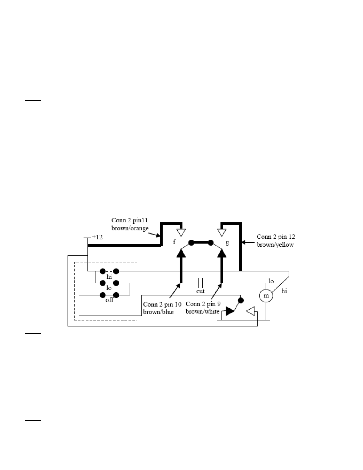
7. Front wipers: Note that the front wipers have five outputs; a low (pulses for intermittent), a high speed, a “soft” spare relay output for intermittent
wiper, a “soft” output wiper down 1 and a “soft” output wiper down 2, allocated to spare relay outputs 1, 2 or 3 if required.
a. The front wiper relays are designed to connect across the existing vehicle switches. An example circuit for a typical car:
Mode 1 (default) Wipers off/intermittent/lo/hi, Wipers begin in off.
1. First press of wiper up button low output toggles on 1 sec every 8 seconds for intermittent wiper.
2. Second press of wiper up button low output latches on for low wiper.
3. Third press of wiper up button low and high both latch on for high wiper.
4. More presses of wiper up button do nothing.
5. First press of wiper down button high output goes off and low stays on for low wiper.
6. Second press of wiper down button low output toggles on 1 sec every 8 seconds for intermittent wiper.
7. Third press of wiper down button both low and high are turned off.
Mode 2 Wipers off/(spare output latched)/lo/hi - operates spare relay (to be defined in spare relay setup for car with sensor wipe. Wipers begin in off.
1. First press of wiper up button, spare relay output intermittent wiper latches on.
2. Second press of wiper up button low output latches on for low wiper, spare relay output intermittent wiper goes off.
3. Third press of wiper up button low and high both latch on for high wiper.
4. More presses of wiper up button do nothing.
5. First press of wiper down button high output goes off and low stays on for low wiper.
6. Second press of wiper down button low output goes off, spare relay output intermittent wiper latches on.
7. Third press of wiper down button low and high and spare relay output intermittent wiper are turned off.
Mode 3 For two momentary outputs (e.g. Wipers used as electric window control)
a. Pressing wiper down button turns low output only on momentarily.
b. Pressing wiper up button turns low and high outputs on momentarily.
Mode 4 Wipers for new Vauxhall & BMW (2 step momentary sticks)
a. Pressing wiper up button operates low for 0.5 sec, then high momentarily until wiper up is released.
Fig. 4
LogiTouch Installation & Setup Instructions, Ver. 2008
Pg. 8
b. Two “soft” outputs wiper down 1 and 2
c. Pressing wiper down button operates “soft” output wiper down 1 for 0.5 sec. then “soft” output wiper down 2 momentarily until wiper up is
released.
Mode 5 Wipers provide off/intermittent/lo - no high speed.
a. First press of wiper up button, low output toggles on 1 sec every 8 seconds for intermittent wiper.
b. Second press of wiper up button, low output latches on for low wiper.
c. More presses of wiper up button do nothing.
d. First press of wiper down button, low output toggles on 1 sec every 8 seconds for intermittent wiper.
e. Second press of wiper down button, wipers are turned off.
Mode 6 Wipers for new Vauxhall & BMW (2 step momentary sticks)
a. Pressing wiper up button operates low for 0.5 sec and then high momentarily until wiper up is released.
b. Two “soft outputs wiper down 1and 2.
c. Pressing wiper down button operates “soft” wiper down 1 for 0.5 sec and then high wiper output momentarily until wiper down is released.
8. Front Washer: The front and rear washer relays are designed to connect across the existing vehicle switches.
a. Example circuit showing a single washer motor for both front and rear wash. Polarity is reversed on the motor, i.e. Volkswagen:
Mode 1 (default) Washer only:
Front washer output is on only while Front washer button is pressed.
Mode 2 Washer and Wipers for four seconds:
a. Front washer output is on only while Front washer button is pressed.
b. Also operates low front wiper while Front washer button is pressed, and holds for 4 seconds after release.
Mode 3 Washer and Wipers for 4.5 seconds: (as Mode 2 but to avoid wiper parking problems)
a. Front washer output is on only while Front washer button is pressed.
b. Also operates low front wiper while Front washer button is pressed, and holds for 4.5 seconds after release.
Mode 4 Washer latching on & off:
Washer toggles on & off when Washer switch is pressed, this is so it can be used for other functions.
9. Rear wash/Wipe: The rear washer relays are designed to usually connect across the existing vehicle switches - see above for example circuit.
Mode 1 (default) Rear Washer momentary and Rear wiper toggles on/off:
a. When Rear wash/Wipe is pressed, rear washer is operated momentarily AFTER it has been pressed for 0.5 seconds.
b. Also when Rear wash/Wipe is pressed, rear wiper is toggled on and off with every press.
c. Rear wiper should always be turned on if rear washer is operated. Rear wipers will keep running if wash is operated, and needs another brief
press of the button to turn them off.
Mode 2 Rear Washer momentary (0.5 sec delay) and toggles on/off Rear wiper intermittent (pulsed 1 second out of 8).
a. When Rear wash/Wipe is pressed, rear washer is operated momentarily AFTER it has been pressed for 0.5 seconds.
b. Anytime rear WASHER is activated (button pressed for more than 0.5 seconds), rear wiper comes on for 4 seconds.
c. Also when Rear wash/Wipe is pressed, rear wiper intermittent (on for 1 second every 8 seconds) is toggled on and off with every press. Also
ensures that the rear wiper is always on while washer is operated.
Mode 3 Rear Washer momentary (0.5 sec delay) and Rear wiper (momentary and latching):
a. When Rear wash/Wipe is pressed, rear washer is operated momentarily AFTER it has been pressed for 0.5 seconds.
b. Anytime rear WASHER is activated (button pressed for more than 0.5 seconds), rear wiper comes on for 4 seconds.
c. “Sequencing”-.Also when Rear wash/Wipe is pressed (from rear wiper off): First press of Rear wash/Wipe switch rear wiper selects intermittent
wiper (on for 1 second every 8 seconds). Second press of Rear wash/Wipe switch rear wiper selects continuous rear wiper. Third press of Rear
wash/Wipe switch rear wiper selects rear wiper off.
Mode 4 (Not implemented yet) Rear wash and rear wipe momentary (both are instantly on, both stay on only while the rear wash button is pressed.)
Mode 5 (Not implemented yet) Rear Washer & Rear wiper no function (so it will not operate on some cars that do not have rear wiper installed)
10. Headlights (off / parklights / headlights) The relays are designed to connect across the existing vehicle switches.
Mode 1 (default) Activates park/headlights/(pressed for 2 seconds) off.
a. Press headlights switch for parklights only to go on.
b. Press again for park and headlights on.
Fig. 5

LogiTouch Installation & Setup Instructions, Ver. 2008
Pg. 9
c. To turn both off, press button for 2 seconds.
Mode 2 Safety interlock.
a. Press headlights switch for parklights only to turn on.
b. Press again for park and headlights on.
c. To turn both off, press headlights switch for 2 seconds.
d. Decoder unit should beep for 2 seconds to indicate lights switched off. Press rear wash/wipe to turn off lights (rear wash/wiper signal will be
ignored and not turn on).
e. If nothing is pressed for 2 seconds it resets to start again.
Mode 3 - General purpose
Pressing headlights switch makes parklights go on momentary, and headlights latching with every button press.
11. Rear fog lights: The relay is designed to connect across the existing vehicle switch.
Mode 1 (default) - latching and turns off with lights
a. Pressing Rear fog lights switch latches rear fog lights output on & off. These will only function if sidelights (or headlights) are on.
b. Turning off sidelights resets rear fog lights output off.
Mode 2 - Momentary
Pressing Rear fog lights switch momentarily turns rear fog lights output on. These will only function if sidelights (or headlights) are on.
Mode 3 - General purpose momentary
Pressing Rear fog lights switch momentarily turns rear fog lights output on.
Mode 4 - General purpose latching
a. Pressing Rear fog lights switch latches rear fog lights output on or off.
12. Front fog lights: The relay is designed to connect across the existing vehicle switch.
Mode 1 (default) - latching & turns off with lights
a. Pressing front fog lights switch latches Front fog lights output on & off. These will only function if parklights (or headlights) are on.
b. Turning off parklights resets front fog lights output to off.
Mode 2 - Momentary
Pressing Front fog lights switch momentarily turns Front fog lights output on. These will only function if sidelights (or headlights) are on.
Mode 3 - General purpose momentary
Pressing Front fog lights switch momentarily turns Front fog lights output on.
Mode 4 - General purpose latching
Pressing Front fog lights switch latches Front fog lights output on or off.
13. Extra function 1: The relay is designed to connect across the existing vehicle switch. This can be used for any extra function required, e.g.
heated rear window.
Mode 1( default) - General purpose momentary
Pressing Extra function 1switch momentarily turns Extra function 1 output on.
Mode 2 - General purpose latching
Pressing Front Extra function 1 switch latches Extra function 1 output on or off.
15. Extra function 2: The relay is designed to connect across the existing vehicle switch. This can be used for any extra function required, e.g.
heated rear window.
Mode 1 (default) - General purpose momentary
Pressing Extra function 2 switch momentarily turns Extra function 1 output on.
Mode 2 - General purpose latching
Pressing Front Extra function 2 switch latches Extra function 1 output on or off.
16. Spare Relay 1, 2 & 3: These are unallocated relays that can be linked in the above & used for different functions. Each spare relay has the
following list of modes (functions with which they operate).
mode 1 (default) No function
mode 2 = Hazards
mode 3 =Front wipers low
mode 4 = front wipers high
mode 5 = Rear wipers on/off.
mode 6 = Rear washer on/off
mode 7 = Both washers on/off
mode 8 = Main beam on/off
mode 9 = Headlights flash on/off
mode 10 =Headlights on/off
mode 11 =Sidelights on/off
mode 12 =Horn
mode 13 =Intermittent wiper
mode 14 =wiper down 1
mode 15 =wiper down 2
mode 16 on Spare relay 1 = Extra function 1, on Spare relay 2 = Extra function 2 (Spare Relay 3 cannot be used with Extra Function 1 or 2)
19. Default: Selecting this sets all the above functions to mode 1 - default setting.
mode 1 (default) No function
20. Clear transmitters function: Selecting this clears all the recognized transmitters so you can start again to only recognize the desired transmitters.
Table of contents
Popular Automobile Accessories manuals by other brands

Menabo
Menabo LOGIC Fitting instructions

Go Rhino
Go Rhino 3293B Assembly instructions

SVC GROUP
SVC GROUP CAR RACE-2 Mounting instructions

JL Audio
JL Audio Stealthbox SB-T-TACACG3/10TW3 installation guide

Thule
Thule HangOn 9708 instructions

dirna Bergstrom
dirna Bergstrom Bycool Green Line Compact 3.0 Mounting instructions

FVC
FVC Sprinter Bed System Flarespace installation guide

Continental Refrigerator
Continental Refrigerator AUTODIAGNOS TPMS SE user guide

Prorack
Prorack PR3104 instructions

injen technology
injen technology EVO1107 installation instructions

Yakima
Yakima BowDown quick start guide

Maxon
Maxon 49-SX owner's manual


