D-Boss LT-40FLP User manual

SERVICE MANUAL PAGE:1
COLOR TFT-LCD TV
SERVICE MANUAL
MODEL : LT-40FLP
CAUTION !!
BEFORESERVICINGTHETFT-LCDTV,
READTHE SAFETY PRECAUTIONS IN THIS MANUAL.
SERVICE MANUAL PAGE:2
SAFETY PRECAUTIONS
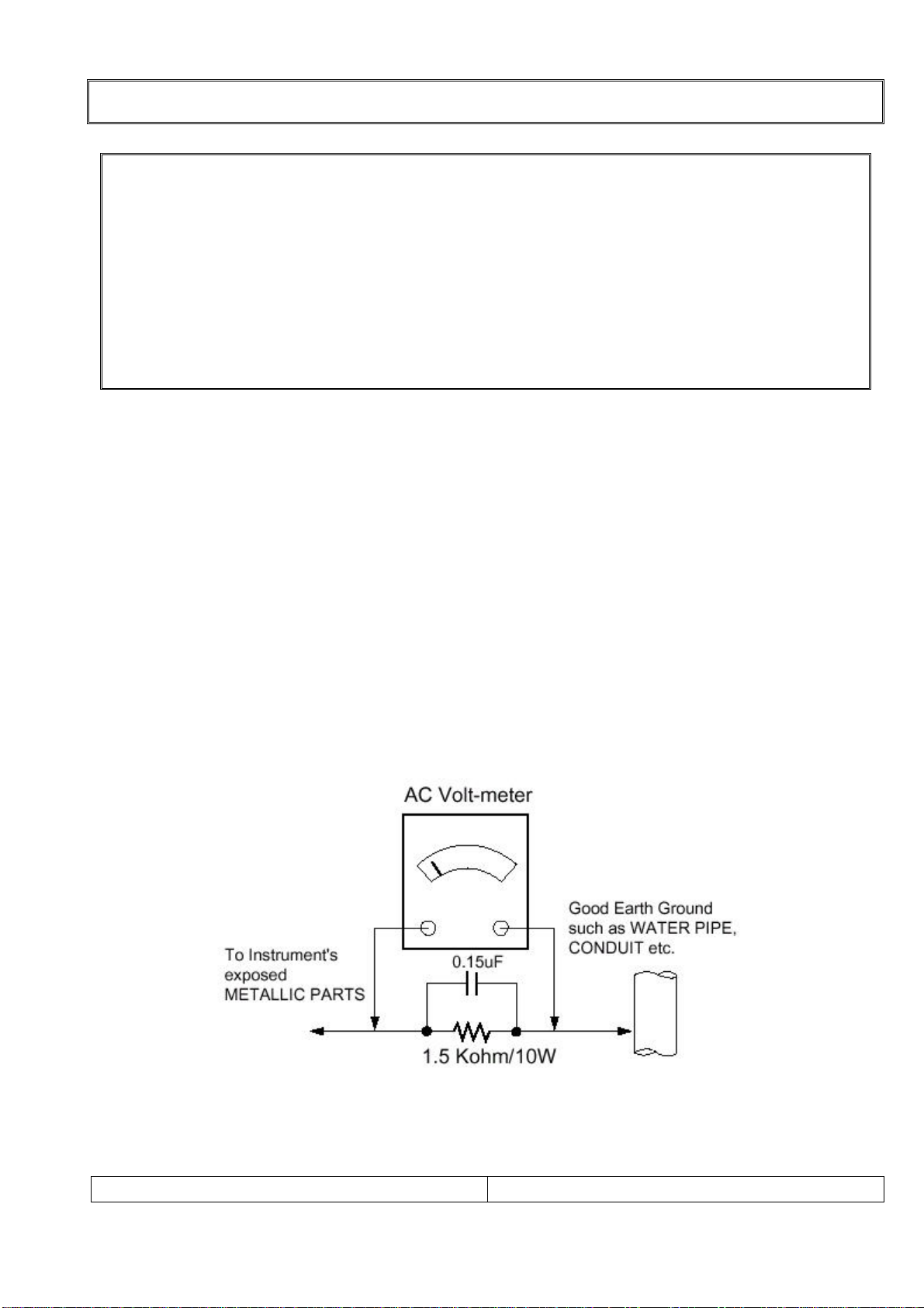
Leakage Current Hot Check (See below Figure)
Plug the AC cord directly into the AC outlet.
Do not use a line Isolation Transformer during this check.
Connect 1.5K/10watt resistor in parallel with a 0.15uF capacitor between a known good earth
ground (Water Pipe, Conduit, etc.) and the exposed metallic parts.
Measure the AC voltage across the resistor using AC voltmeter with 1000 ohms/volt or more
sensitivity.
Reverse plug of the AC cord into the AC outlet and repeat AC voltage measurements for each
exposed metallic part. Any voltage measured must not exceed 0.75 volt RMS, which is,
corresponds to 0.5mA.
In case any measurement is out of the limits specified, there is possibility of shock hazard and
the set must be checked and repaired before it is returned to the customer.
Leakage Current Hot Check circuit
!! Important Safety Notice !!
Many electrical and mechanical parts in this chassis have special safety-related
characteristics.
These parts are identified by in the Schematic Diagram and Replacement Parts List.
It is essential that these special safety parts should be replaced with the same components
as recommended in this manual to prevent Shock, Fire, or other Hazards.
Do not modify the original design without permission of manufacturer.

SERVICE MANUAL PAGE:3
SERVICING PRECAUTIONS
CAUTION!!
Before servicing receivers covered by this service manual, read and follow the SAFETY
PRECAUTIONS on page 2 of this publication.
General Servicing Precautions
1.Always unplug the receiver AC power cord from AC power source before;
ⓐRemoving or reinstalling any component, circuit board module or any other receiver assembly.
ⓑDisconnecting or reconnecting any receiver electrical plug or other electrical connection.
ⓒConnecting a test substitute in parallel with an electrolytic capacitor in the receiver.
CAUTION!! A wrong part substitution or incorrect polarity installation of electrolytic capacitors
may result in an explosion harzard.
2.Do not spray chemicals on or near this receiver or any of its assemblies.
3.Do not defect any plug/socket voltage interlocks with which receivers covered by this service
manual might be equipped.
4.Always connect the test receiver ground lead to the receiver chassis ground before
connecting the test receiver positive lead. Always remove the test receiver ground lead last.
5.Do not connect the test fixture ground strap to power supply heatsink in this receiver
Electrostatically Sensitive(ES) Devices
Some semiconductor(solid state) devices can be damaged easily by static electricity. Such
components commonly are called Electrostatically Sensitive(ES) Device.Examples
Circuit Board Foil Repair
Excessive heat applied to the copper foil of any printed circuit board will weaken the adhesive
that bonds the foil to the circuit board causing the foil th separate from or “lift-off” the board.
The following guidelines and procedures should be flollowed whenever this condition is
encountered.
At IC Connections
To repair a defective copper pattern at IC connections use the following procedure to install a
jumper wire on the copper pattern side of the circuit board.(Use this technique only on IC
connections.)
1.Carefully remove the damaged copper pattern with a sharp knife.(Remove only as much
copper as absolutely necessary.)
2.Carefully scratch away the solder resist and acrylic coating(if used) from the end of the
remaining coopper pattern.
3.Bend a small “U” in one end of a small guage jumper wire and carefully crimp it around the IC
pin.
4.Route the jumper wire along the path of the out-away copper pattern and let it overlap the
previously scraped end of the good copper pattern. Solder the overlapped area and clip off any
excess jumper wire.

SERVICE MANUAL PAGE:4
CONTENTS
Safety precautions ----------------------------------------------------------- 2
Servicing precautions ------------------------------------------------------- 3
Contents ------------------------------------------------------------------------- 4
Specifications ----------------------------------------------------------------- 5
Location of control ---------------------------------------------------------- 9
Deassembly procedure ---------------------------------------------------- 12
Mechanical exploded view with part list ----------------------------- 19
Circuit descriptions --------------------------------------------------------- 21
Trouble shooting ------------------------------------------------------------- 58
Wire dressing ----------------------------------------------------------------- 63
Adjustment instruction with SVC mode ------------------------------ 65
Inspection instruction ------------------------------------------------------ 69
PCB Layout --------------------------------------------------------------------- 71
Part appearance -------------------------------------------------------------- 76
Replacement part list -------------------------------------------------------- 79
Block diagram ---------------------------------------------------------------- 90
Connection diagram -------------------------------------------------------- 91
Schemetic diagram --------------------------------------------------------- 92
Wave form --------------------------------------------------------------------- 93

SERVICE MANUAL PAGE:5
SPECIFICATIONS
Note: Specifications and others are subject to change without notice for improvement.
1.Scope.
This document is the specification of 40” TFT-LCD Color TV.
2.Power
1) Power requirement
275W
2) AC / DC SMPS Adapter.
Input Frequency : 50/60㎐
Input Voltage: AC 100V ~AC 240V (±10%)
Output Voltage: DC 5V,12V, 30V,
3) Power cord
Use UL listed and CSA certified detachable power cord type; SVT, 3-conductors, 18AWG
For AC 120V area. Use VDE listed detachable power cord type; HO5VV-F, 3-conductors,
18AWG for AC 220~240V area.
3.Tuning system
FVS 100 Program
4.Sound output
10W+10Wrms Stereo (Max)
5.Antenna input impedance
VHF / UHF at 75ohm
6.OSD Type (On Screen Display)
Windows type (Center)
7.External in/output
DVI-INPUT,S-VIDEO INPUT,HEADPHONE OUTPUT,ANALOG PC INPUT,PC AUDIO INPUT,
SCART 2 INPUT ,SUB WOOFER OUTPUT,ANTENNA INPUT
8. Function
CATV/Hyper band
Auto Program
Manual Program
Auto Sleep
Quick view
ACMS(Auto channel Memory System)
PSM(Picture Status memory)
SSM(Sound Status memory)
PIP(PICTURE IN RICTURE)
ARC(ASPECT RATIO CONTROL)

SERVICE MANUAL PAGE:6
SPECIFICATIONS
9.Receiving RF TV system
NO
Model System 40FLP / /
1 PAL-B ○/ /
2 PAL-G ○/ /
3 PAL-I, I /I ○/ /
4 PAL-D ○/ /
5 PAL-K ○/ /
6 SECAM-B ○/ /
7 SECAM-G ○/ /
8 SECAM-D ○/ /
9 SECAM-K ○/ /
10 SECAM-K1 ○/ /
11 SECAM-I (6.0) ○/ /
12 NTSC-3.58 / 4.5 ○/ /
13 NTSC-3.58 / 5.5 ○/ /
14 NTSC-3.58 / 6.0 ○/ /
15 NTSC-3.58 / 6.5 ○/ /
16 NTSC-3.58 / 4.5(5.0) ○/ /
17 NTSC-4.43 / 5.5 ○/ /
18 NTSC-4.43 / 6.0 ○/ /
19 NTSC-4.43 / 6.5 ○/ /
20 PAL 5.5 / 60Hz ○/ /
21 PAL 6.0 / 60Hz ○/ /
22 PAL 6.5 / 60Hz ○/ /
23 SECAM 5.5 / 60Hz ○/ /
24 SECAM 6.0 / 60Hz ○/ /
25 SECAM 6.5 / 60Hz ○/ /
26 SECAM L / L' X //
TOTAL SYSTEM 25 //

SERVICE MANUAL PAGE:7
11. PC Mode Scan Frequency & Timing
1) Scan Freq: H: 15 ~110 kHz / V: 56 ~75㎐
2) Preset Timing Chart
Mode Resolution H-Freq(KHz) V-Freq(KHz)
VGA
640x480
640x480
640x480
640x480
720x400
31.5KHz
35 KHz
37.9KHz
37.5KHz
31.5KHz
60Hz
67Hz
72Hz
75Hz
70Hz
SVGA
800x600
800x600
800x600
800x600
35.1KHz
37.9KHz
48.1KHz
46.9KHz
56Hz
60Hz
72Hz
75Hz
XGA
1024x768
1024x768
1024x768
48.4KHz
56.5KHz
60.2KHz
60Hz
70Hz
75Hz
WXGA 1280x768 47.7KHZ 60Hz
Note!! :
ⓐIf the set is cold, there may be a small “flicker” when the set is switched on. This is
Normal, there is nothing wrong with the set.
ⓑif possible, use the VESA 1024 x 768@60HZ video mode to obtain the best image
quality for your LCD monitor. If used under the other resolutions, some scaled or processed
pictures may appear on the screen.
ⓒ some dot defects may appear on the screen, like Red, Green or Blue spot.
However, this will have no impact or effect on the monitor performance.
SPECIFICATIONS

SERVICE MANUAL PAGE:8
13. TFT – LCD Panel Character
1) Feature
Size : 40 inches diagonal
LCD Type : a-si TFT Active MatriX
Pixel Pitch : 0.681mm (V) x 0.681mm(H) x RGB
Pixel Format : 1280 horiz. By 768 vert. Pixels RGB strip arrangement
Active Video Area : 871.68mm (H) x 523.008 mm (V)
Surface treatment : Haze 44% , Hard coating (3H)
Response Time (Typ) : Tr : 15 ms Tf : 8 ms
Viewing Angle<CR≥10> : Hor [Left/Right] Æ85Deg (Typ) / 85Deg (Typ),
Ver [High (Top)/Low (Bottom)] Æ85Deg (Typ) / 85Deg (Typ)
Luminance(Typ) : 450 cd/㎡(Typ)
Contrast Ratio (Typ) : 600(Typ)
DisplayColor :16.7MColor
BackLight :20CCFL
SPECIFICATIONS

SERVICE MANUAL PAGE:9
LOCATION OF CONTROL
All the function can be controlled with the remote controller.
Some functions can also adjusted with the buttons on the controls on the TV front panel.
1-1. Remote controller
Note !! : Before you use the remote controller, please install the batteries.
1.POWER:
Turns the TV on from standby or off to
standby mode.
2.MUTE:
Turns the sound on and off
3.NUMBER buttons:
Select channel numbers.
4.PSM (Picture Status Memory):
Recalls your preferred picture setting.
5.SSM (Sound Status Memory):
Recalls your preferred sound setting.
6. I / II:
Selects the language during dual
language broadcast. / Selects the
sound output.
7.MENU:
Displays a main menu.
8.TV / AV:
Selects input signal source.
/ Clears the menu from the screen.
9.SLEEP:
Sets the sleep timer.
10.TV / PC :
Selects TV or PC mode directly.
11.Information Display
Use to see information on the current
boardcast
12. TV
The future reserved
SERVICE MANUAL PAGE:10
LOCATION OF CONTROL
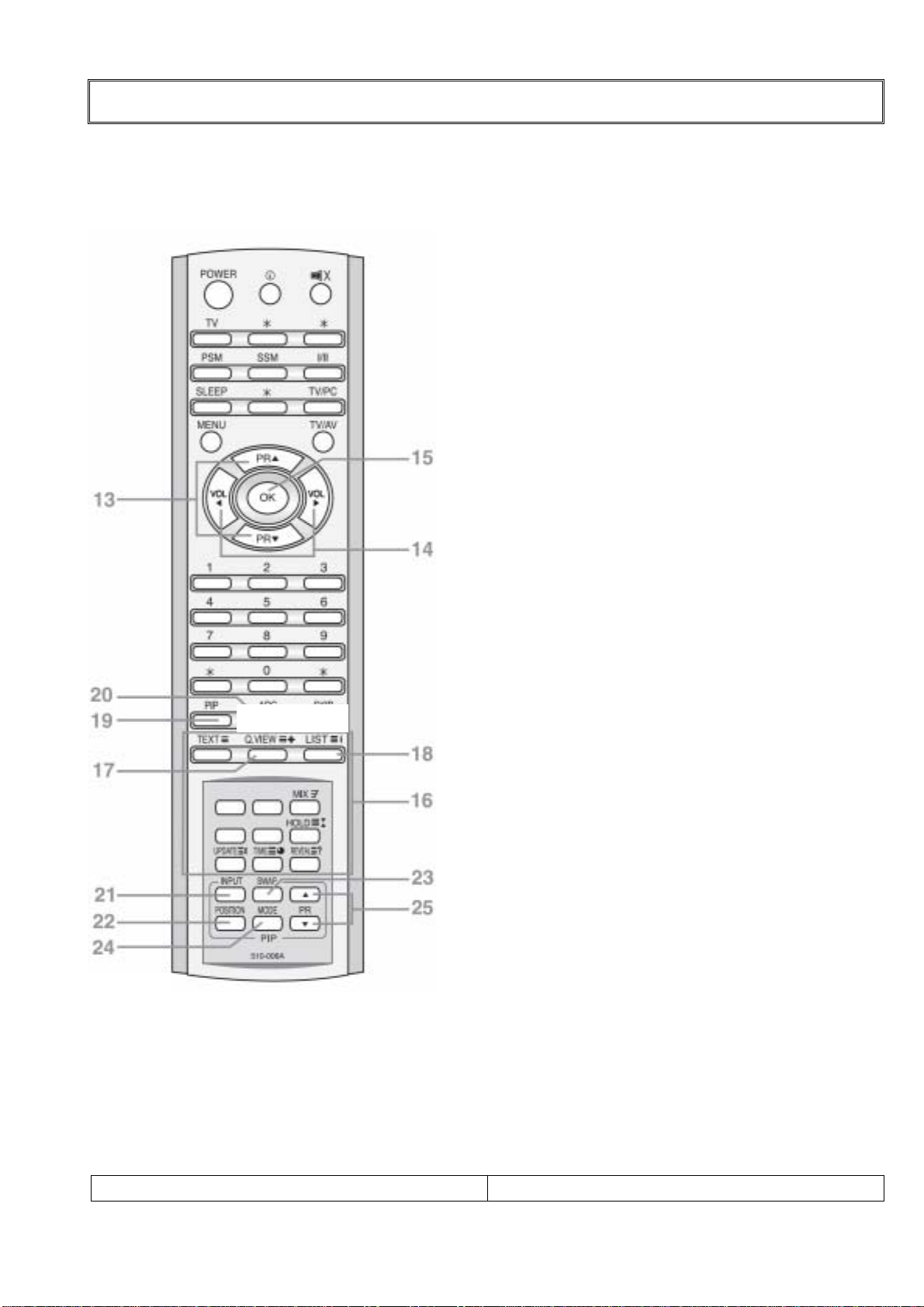
1-2. Remote controller
Note !! : Before you use the remote controller, please install the batteries.
13.PR ▲▼ ( Programme Up/Down):
Selects a next programme or a menu item.
14.VOL ◀▶ ( Volume Up/Down):
Adjusts the sound level or a menu Setting.
15.OK
Accepts your selection or displays the current mode.
16. TELETEXT Buttons:
These buttons are used for TELETEXT. For further
details, see the TELETEXT Selection.
17. Q.VIEW
Returns to the previously viewed Programme
Note: TELETEXT mode.
The Q.VIEW button is used for TELETEXT function.
18. LIST
Displays the program list menu.
19. PIP
Display a PIP (Picture In Picture) screen.
20. ARC
Selects a screen mode – 16:9, 14:9, ZOOM, 1:1 and
auto Wide.
21. INPUT
Selects the AV source of sub picture in PIP mode.
22. POSITION
Selects a position of PIP screen.
23. SWAP
Switches a main picture for sub picture in PIP mode.
24. MODE
Selects a PIP screen mode – 16:1,9:1,double window
and scan mode
25.▲PR▼
Selects a programme when RF signal is displayed in
PIP mode.

SERVICE MANUAL PAGE:11
LOCATION OF CONTROL
Controller of Panel
< SIDE VIEW>
1.ON/OFF:
Switches TV set on or off.
2.MENU:
Display a menu.
3.+ PR -( Programme Up/Down):
Selects a programme or a menu item.
4.+ VOL -( Volume Up/Down):
Adjusts the volume.
Adjusts menu settings.
5.TV/AV:
Selects input signal source.
Clears the menu from the screen.
6:POWER INDICATOR:
Illuminates red when the TV is in-
power standby mode.
Illuminates green when the TV is-
switched power on mode.
Illuminates amber when the TV is-
switched power saving mode.
7.REMOTE CONTROL SENSOR:
Accepts the IR signal of remote
controller.

SERVICE MANUAL PAGE:12
DISASSEMBLY PROCEDURE
1. Disassembly procedure
1).Back cover
Remove 8 Screw
Remove 20 Screw & Power cord holder
Power cord holder

SERVICE MANUAL PAGE:13
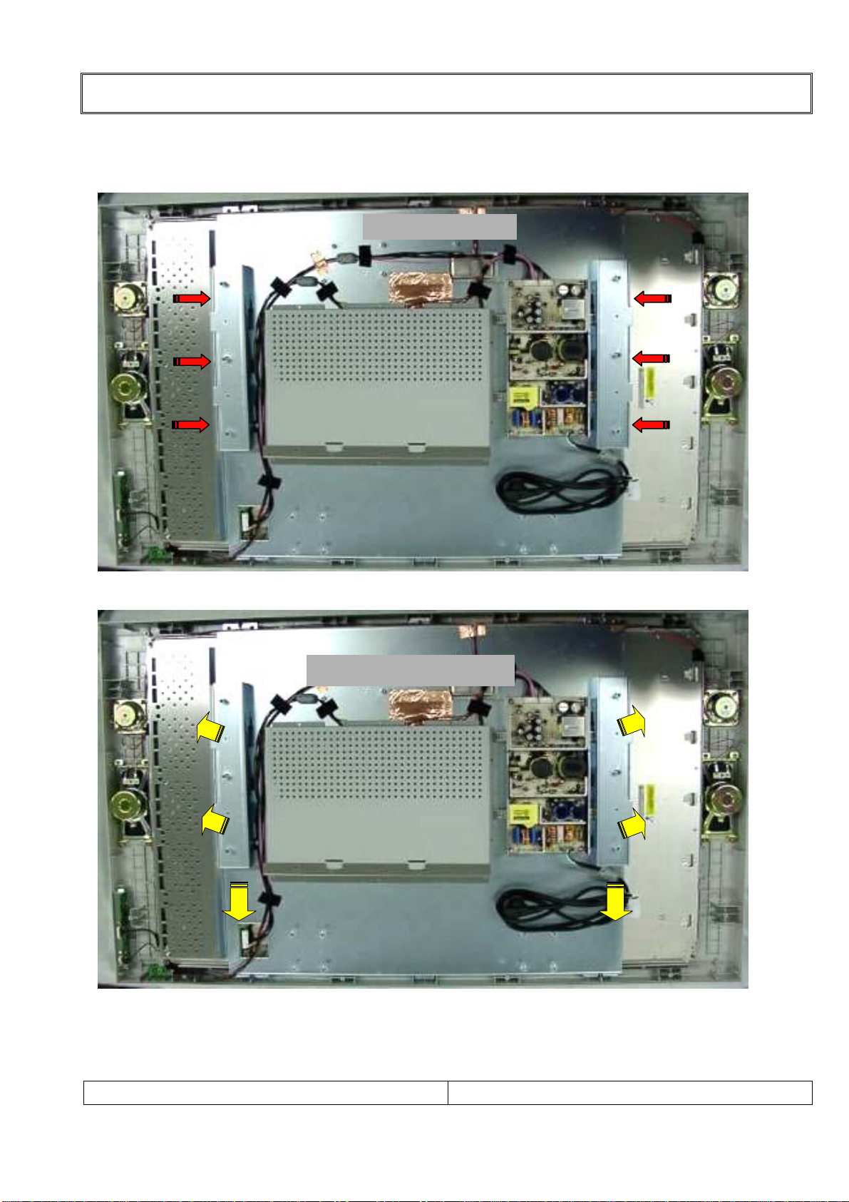
DISASSEMBLY PROCEDURE
2-1). Metal plate & Rear chassis
Remove 10 Screw
Removal of Rear & Terminal metal plate
SERVICE MANUAL PAGE:14
DISASSEMBLY PROCEDURE
2-2). Metal plate & Rear chassis
Remove 6 Connectors
Removal of Mount metal plate
SERVICE MANUAL PAGE:15
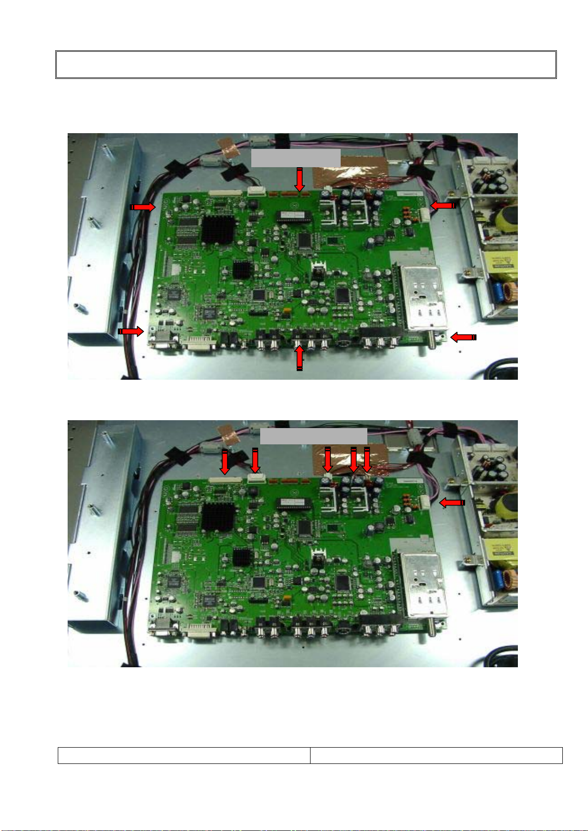
3).Main PWB & Connectors
DISASSEMBLY PROCEDURE
Remove 6 Screw
Remove 6 Connectors

SERVICE MANUAL PAGE:16
4). SMPS Board & Power cord
DISASSEMBLY PROCEDURE
Remove 4 Screw & 2 Connectors
Remove Power Cord

SERVICE MANUAL PAGE:17
DISASSEMBLY PROCEDURE
5-1). LCD Module
Remove 4 brackets, then lift out LCD Module
Removal of LCD Panel module mounting brackets
Remove 14 Screw

SERVICE MANUAL PAGE:18
DISASSEMBLY PROCEDURE
5-2). LCD Module
Front mask remains after
removing LCD Module
Front mask remains after
removing LCD Module

SERVICE MANUAL PAGE:19
MECHANICAL EXPLODED VIEW
1. Explode View
N0 1 2 3 4 5 6 7 8 9 10 11 12 13 14 15 16 17 18 19 20 21 22 23 24 25
PART
NAME
402-
004X,Y 400-011T AYCOLT32A01A 404-004A 450-001D 610-005A 610-005B 501-016T
PANV400W100
0 407-004F 407-004G 407-004L
AYMALT34A01
A 620-005A 407-004H 407-004J 401-003A 402-004Z 450-002C- 410-
001Q 410-001K 410-002L 410-001R 410-002C
FRONT CONTROL BLOCK DECO SPEAKER
SPEAKE
R STICKER SHIELD SHIELD MAIN PCB AC/DC SHIELD SHIELD BACK CORD DECO SCREW SCREW SCREW SCREW SCREW
DESCRIPTIO
N DECO(T,B) COVER IR PCB PCB KNOB PLATE 20W, 8Ω10W, 8ΩLOGO PANEL FIX BRKT FRONT MOUNT(L,R
)
ASS'Y ADAPTE
R
REAR JACK COVER HOLDER PLATE BTB 4*12 TTB 3*8 PBTB 3*10 PB 4*8 PB 3*6
MATERIAR PMMA PC+ABS - - ABS PVC - - NI SAMSUNG EGI EGI EGI - - EGI SPTH PC+ABS ABS PVC SZN SZN SZN SZN SZN
COLOR
FISH MIRROR SILVER - - SILVER SILVER - - SILVER - - - - - - - - DARK GRAY DARK GRAY BLACK - - - - -
Q'TY (EA) EACH 1 1 1 1 1 1 2 2 1 1 4 1 EACH 1 1 1 1 1 1 1 1 50 7 3 14 21
REMARK CONTROL REAR
TAPPIN
G
TAPPIN
G TAPPING MACHINE MACHINE
SET ASS'Y

SERVICE MANUAL PAGE:20
MECHANICAL EXPLODED VIEW
1-1,. Explode View
- option
Table of contents
Other D-Boss LCD TV manuals


