DAT DHC-X100N User manual

1. SAFETY PRECAUTIONS......................................................2/3
2. SPECIFICATIONS....................................................................4
3. LOCATION OF USERS CONTROLS....................................5/7
FRONT PANEL
REAR PANEL
DISPLAY
REMOTE CONTROLLER
4. CONNECTING TO EQUIPMENT...........................................8/9
CONNECTING TO TV
CONNECTING TO AUDIO & VIDEO
CONNECTING TO SPEAKER
5. TROUBLE SHOOTING GUIDE.........................................10/14
6. DVD PROGRAM DOWNLOAD METHOD..............................15
7. WAVEFORMS OF MAJOR CHECK POINT......................16/17
AUDIO OUT SIGNAL WAVEFORM
DAC OUTPUT SIGNAL WAVEFORM
OPTICAL OUTPUT AUDIO DATA SIGNALFORM
L/R CLOCK DATA WAVEFORM DURING NORMAL PLAY
SERIAL DATA OUTPUT WAVEFORM DURING NORMAL PLAY
Pr OUTPUT DATA WAVEFORM IN COMPONENT OUTPUT
Pb OUTPUT DATA WAVEFORM IN COMPONENT OUTPUT
Y OUTPUT DATA WAVEFORM IN COMPONENT OUTPUT
8. INTERNAL BLOCK DIAGRAM OF ICs............................18/22
9. BLOCK DIAGRAM.................................................................23
10. WIRING DIAGRAM...............................................................24
11. SCHEMATIC DIAGRAM..................................................25/29
FRONT
Mi-COM
INPUT/VIDEO
AMP
POWER
12. PRINTED CIRCUIT DIAGRAM........................................30/33
MAIN
IN/OUT
FRONT [DHC-150 Only]
13. EXPLODED VIEW AND MECHANICAL PARTS LIST...34/37
MECHANICAL EXPLODED VIEW
MECHANICAL PARTS LIST
14. ELECTRICAL PARTS LIST......................................Appendix
Contents
1
DIGITALHOMECINEMASYSTEM
[* DVD-DR4033 for Quelle] DHC-X100N
DHC-X150N
Service Manual
S/N No. :
FEB. 2004
DAEWOO DAT CO., LTD.
Mini Component System
Model:
Digital Home Cinema System
MENU/RETURN
ANGLE
TIME
DHC-X100N/X150N
S
T
A
N
D
B
Y
/
O
N
MENU/RETURN
ANGLE
TIME
[DHC-X100N]
[DHC-X150N]
9CD8302200

1. Safety Precautions 1. Safety Precautions
WARNING
: TO PREVENT FIRE OR ELECTRIC SHOCK, DO NOT EXPOSE
THIS APPLIANCE TO RAIN OR MOISTURE.
CAUTION :
TO REDUCE THE RISK IF ELECTRIC SHOCK, DO NOT
REMOVE COVER (OR BACK). NO USER SERVICEABLE PARTS
INSIDE.
REFER SERVICING TO QUALIFIED SERVICE PERSONNEL.
THIS SYMBOL IS INTENDED TO ALERT THE USER TO THE
PRESENCE OF UNINSULTED "DANGEROUS VOLTAGE"
WITHIN THE PRODUCT'S ENCLOSURE THAT MAY BE
SUFFICIENT MAGNITUDE TO CONSTITUTE A RISK OF
ELECTRIC SHOCK TO PERSONS.
THIS SYMBOL IS INTENDED TO ALERT THE USER TO THE
PRESENCE OF IMPORTANT OPERATING AND MAINTENANCE
(SERVICING) INSTRUCTIONS IN THE LITERATURE
ACCOMPANYINGTHEAPPLIANCE.
CAUTION
TO PREVENT ELECTRIC SHOCK, DO NOT USE THIS POLARIZED AC
PLUG WITH AN EXTENSION CORD, RECEPTACLE OR OTHER OUTLET
UNLESS THE BLADES CAN BE FULLY INSERTED TO PREVENT BLADE
EXPOSURE.
LASER SAFETY
THISUNITEMPLOYSA LASER.ONLYQUALIFIEDSERVICE PERSONNEL
SHOULD REMOVE THE COVER OR ATTEMPT TO SERVICE THIS DEVICE
DUE TO POSSIBLE EYE INJURY.
CAUTION:
USE OFANYCONTROLS, ADJUSTMENTS, ORPROCEDURES
OTHER THAN THOSE SPECIFIED HEREIN MAY RESULT IN HAZARDOUS
RADIATION EXPOSURE.
CAUTION :
TO PREVENT ELECTRIC SHOCK, MATCH WIDE BLADE OF
PLUG TO WIDE SLOT, FULLY INSERT.
ATTENTION :
POUR EVITER LES CHOCS ELECTRIQUES, INTRODUIRE
LA LAME LA PLUS LARGE DE LA FICHE DANS LA BORNE CORRESPON-
DANTE DE LA PRISE ET POUSSER JUSQU'AU FOND.
Important Safety Instructions
- All the safety and operating instructions should be read before
the appliance is operated.
- The safety and operating instructions should be retained for
futurereference.
- All warnings on the appliance and in the operating instructions
shouldbe adhered to.
- All operating and use instructions should be followed.
1. Water and Moisture - The appliance should not be used near
water - for example, near a bathtub, washbowl, kitchen sink,
laundry tub, in a wet basement, or near a swimming pool,
and the like. 2. Carts and Stands - The appliance
should be used only with a cart or
stand that is recommended by th
manufacturer.
3. An appliance and cart combination
should bemoved with care. Quick
stops, excessive force, and uneven
surfaces may cause the appliance
and cart combination to overturn.
4. Wall or Ceiling Mounting - The appli-
ance should be mounted to a wall or
ceiling only as recommended by the manufacturer.
5. Ventilation - The appliance should be situated so that its
location or position does not interfere with its proper
ventilation. Forexample, the applianceshouldnotbe situated
on a bed, sofa, rug, or similar surface that mayblock the
ventilation openings; or, placed in a built-in installation, such
as a bookcase or cabinet that may impede the flow of air
through the ventilation openings.
6. Heat - Theappliance should be situatedaway from heat
sources such as radiators, heat registers, stoves, or other
appliances (including amplifiers) that produceheat.
7. Power Sources - The appliance should be connected to a
power supply only of the type described in the operating
instructions or as marked on the appliance.
8. Grounding or Polarization - The precautions that should be
taken so that the grounding or polarization means of an
appliance is not defeated.
9. Power - Cord Protection - Power-supply cords should be
routed so that they are not likely to be walked on or pinched
by items placed upon or against them, paying particular
attention to cords at plugs, convenience receptacles, and the
point where they exit from the appliance.
10.Protective Attachment Plug - If the appliance is equipped with
an attachment plug having overload protection. This is a
safety feature. See Instruction Manual for replacement or
resetting of protective device. If replacement of the plug is
required, be sure the service technician has used a
replacement plug specified by the manufacturer that has the
same overload protection as the original plug.
11.Cleaning - The appliance should be cleaned only as
recommended by the manufacturer.
12.Power Lines - An outdoor antenna should be located away
from power lines.
CAUTION
RISK OF ELECTRIC SHOCKS
DO NOT OPEN
PORTABLE CART
Figure2
13.Outdoor Antenna Grounding- If an outside antenna is
connected to the receiver be sure the antenna system is
grounded so as to provide some protection against voltage
surges and built-up static charges. Article 810 of the National
ElectricalCode, ANSI/NFPA 70, provides information with
regard to proper grounding of the mast and supporting
structure, grounding of the lead-in wire to an antenna-dis
charge unit, size of grounding conductors,location of antenna-
discharge unit, connection to grounding electrodes and
requirements for the grounding electrode. See Figure 1.
14.Non-use Periods - The power cord of the appliance should be
unplugged from the outlet when left unused for a long period
of time.
15.Objectand Liquid Entry - Care shouldbetaken so that objects
donot fallandliquids arenotspilled intotheenclosure through
openings.
16.Damage Requiring Service - The appliance should be
serviced by qualified service personnel when:
a) The power-supply cord or the plug has been damaged; or
b) Objects have fallen, or liquid has been spilled into the
appliance; or
c) The appliance has been exposed to rain; or
d) The appliance does not appear to operate normally or
exhibits a marked change in performance; or
e) The appliance has been dropped, or the enclosure
damaged.
17.Servicing - The user should not attempt to service the
appliance beyond that described in the operating instructions.
All other servicing should be referred to qualified service
personnel.
ANTENNADISCHARGEUNIT
(NECSECTION810-20)
ANTENNALEAD
INWIRE
POWERSERVICE GROUNDING
ELECTRODESYSTEM
(NECART 250PART H)
GROUNDCLAMP
ELECTRIC
SERVICE
EQUIPMENT
GROUNDINGCONDUCTORS
(NECSECTION 810-21)
GROUNDCLAMPS
EXAMPLEOF ANTENNA
GROUNDING
NEC- NATIONAL ELECTRICAL CODE
2 3

2. Specifications
Power supply AC 110V or 120V or 127V / 60Hz
Voltage ( Option ) 220V or 230V or 240V / 50Hz
Power consumption Standby 2Watt
Operating 90Watt
Dimensions (W x D x H) / Weight 360 x 380 x 70mm/ 6.0 kg
POWER OUTPUT at 10% THD
THD(TOTAL HARMONIC DISTORTION)
INPUT SEN. / Impedance @ 1KHz, 47K ohms
FREQUENCY RESPONSE Large
Small
S/N RATIO, IHF-A WEIGHTED
SUBWOOFER TURNOVER FREQUENCY
CHANNEL SEPARATION
at 1KHz, 6 ohms
at 1KHz, 1W
VIDEO, TV/AUX
at 1KHz, 1W
at 1KHz, 1W
VIDEO, TV/AUX
1KHz
17W
0.2%
500mV±30mV/47K
30Hz~20KHz
100Hz~20KHz
70dB
≤120Hz
60dB
Front Amp. Section
Center Amp Section
Video Section
Input Sen. / Impedance
Output Level / Impedance
Color Bar 100%
Frequency Response
Crosstalk
S/N Ratio
Composite Video(Video)
Composite 75 ohm
S-Video(Y/C) 75 ohm(DVD only)
Component Out(Y / Pb / Pr):Option
G, R, B(Scart) Out : Option
Ref 500KHz
@1MHz
DVD
1Vp-p/75 ohm
1Vp-p/75 ohm
1Vp-p/ 0.286Vp-p
1Vp-p/0.7Vp-p/0.7Vp-p
0.7Vp-p/0.7Vp-p/0.7Vp-p
45dB
60dB
±50 mV
±50 mV
±50 mV
±50 mV
±50 mV
5Hz~5.7MHz
40dB
POWER OUTPUT at 10% THD
THD(TOTAL HARMONIC DISTORTION)
S/N RATIO, IHF-A FILTER
FREQUENCY RESPONSE(Dolby Digital) : Small
At 1KHz, 6 ohms
At 1KHz, 1W
1W
1W
17W
0.2%
70dB
100Hz~20KHz
General specifications
FM Tuner Section (FM ANT Impedance : 75 ohms)
Tuning Range
Scanning
Frequency Interval
Usable Sensitivity,
75 ohms
S/N Ratio @1mV
IHF-A FILTER
USA Version
Europe Version
USA Version
Europe Version
S/N=30dB,USA Version
S/N=26dB,Europe Version
Mono USA Version
Mono Europe Version
Stereo USA Version
Stereo Europe Version
87.5~108.0MHz
87.5~108.0MHz
100KHz
50KHz
2uV(17.2dBf)
3uV(20.8dBf)
70dB
70dB
65dB
65dB
POWER OUTPUT 10% THD
THD(TOTAL HARMONIC DISTORTION)
S/N RATIO, IHF-A FILTER
FREQUENCY RESPONSE(Dolby Digital) : Small
Rear Amp Section
At 1KHz, 6 ohms
At 1KHz, 1W
1W
1W
17W
0.2%
70dB
100Hz~20KHz
Subwoofer Section
POWER OUTPUT at 10% THD
FREQUENCY RESPONSE
S/N RATIO, IHF-A Weight
At 100Hz, 8 ohms
1W 30W
20Hz~150Hz
70dB
AM Tuner Section (AM Loop antenna)
Tuning Range
Scanning
Frequency Interval
Usable Sensitivity,
75 ohms
S/N Ratio @1mV
IHF-A FILTER
USA Version
Europe Version
USA Version
Europe Version
S/N=20dB,USA Version
S/N=20dB,Europe Version
USA Version
Europe Version
530~1710KHz
522~1620KHz
10KHz
9KHz
54 dBu
54 dBu
40 dB
40 dB
4
3. Location of Users Controls
Front Panel
5
1. STANDBY indicator
2. STANDBY / ON button
3. DVD/VIDEO CD/MP3 CD/audio CD disc tray
4. OPEN/CLOSE ( ) button
5. PLAY ( ) button
6. STOP ( ) button
7. PREV ( ) button
8. NEXT ( ) button
9. FUNCTION button
10. Remote Control Sensor
11. Display
12. MASTER VOLUME control
13. PHONES jack
[DHC-X100N]
S
T
A
N
D
B
Y
/
O
N
1. STANDBY indicator
2. STANDBY / ON button
3. DVD/VIDEO CD/MP3 CD/audio CD disc tray
4. Remote Control Sensor
5. Display
6. MASTER VOLUME control
7. OPEN/CLOSE ( ) button
8. PLAY ( ) button
9. STOP ( ) button
10. PREV ( ) button
11. NEXT ( ) button
12. FUNCTION button
13. PHONES jack
[DHC-X150N]

7
3. Location of Users Controls
Remote Controller
3. Location of Users Controls
6
1. Pro Logic indicator
2. DOLBY DIGITAL indicator
3. DTS indicator
4. DVD indicator
5. VCD indicator
6. MP3 indicator
7. SLEEP indicator
8. REPEAT indicator
9. ALL indicator
10. TOTAL indicator
11. REMAIN indicator
12. RDS indicator
13. PLAY indicator
14. PAUSE indicator
15. TITLE indicator
16. CHAPTER indicator
17. TRACK indicator
18. DSP indicator
19. STEREO indicator
20. RANDOM indicator
21. MUTE indicator
22. PBC(Playback Control) indicator
23. PLAYING INFORMATION display
1. STANDBY/ON button
2. OPEN/CLOSE button
3. MUTE button
4. INPUT SELECTOR: DVD button
/ TV SYSTEM button
5. INPUT SELECTOR: TUNER(FM/AM) button
6. INPUT SELECTOR: VIDEO, TV/AUX button
7. FAST REVERSE(FR) ( ) button
8. SKIP PREV ( ) button
9. SPEAKER SETUP button
10. CH LEVEL button
11. PLAY ( ) button
12. STOP( ) button
13. MENU/RETURN button
14. PAUSE/STEP button
15. Number buttons
16. DISPLAY/FM MODE button
17. TEST TONE button
18. SUBTITLE button
19. SLOW button
20. A-B REPEAT button
21. ANGLE button
22. RANDOM button
23. DIGEST/RDS MODE button
24. MPX/PTY SEARCH button
25. SLEEP button
26. FAST FORWARD(FF) ( ) button
27. SKIP NEXT ( ) button
28. MOVE /ENTER buttons
29. SURROUND MODE button
30. TITLE button
31. VOLUME buttons
32. SET-UP button
33. GO TO/AUTO MEMORY button
34. DELAY TIME button
35. AUDIO button
36. ZOOM button
37. REPEAT button
38. PBC button
/ / /
/
Display
1. AUDIO IN jacks
2. VIDEO IN jack
3. MONITOR OUT jack
4. DIGITAL OUTPUT jack
5. S VIDEO OUT jack
6. SCART jack or COMPONENT VIDEO OUTPUT
Y/Pb/Pr jacks(Optional)
7. Power cord
8. AM ANTENNA connector
9. FM ANTENNA connector
10. FRONT SPEAKER connectors
11. CENTER SPEAKER connectors
12. WOOFER SPEAKER connector
13. REAR SPEAKER connectors
14. SUBWOOFER output jack
S-VIDEO OUT
(DVD ONLY)
Rear Panel

4. Connecting to Equipment
Connecting to Speaker
9
Connecting to AUDIO & VIDEO
4. Connecting to Equipment
Connecting to TV
8
S-VIDEO OUT
(DVD ONLY)
S-VIDEO OUT
(DVD ONLY)
MUSIC, MOVIE, STADIUM)
S-VIDEO OUT
(DVD ONLY)
To prevent damage to circuits, never short-circuit the positive (+) and negative (-) speaker wires.
Do not connect the speaker cable to the L and R connectors at the same time and do not connect more
than one speaker to the same speaker connectors.

5. Trouble Shooting Guide
11
Push power on.
Check Power down line.
Check if IC750
Pin24 is High ?
Replace IC750
No
Yes
Check if IC750
Pin25 is High ?
Yes
Check Protection Circuit.
No
Replace XC750.
Check Oscillator
of XC750.
Check DVD Reset control.
Check if IC400
Pin3 is work?
Yes
No
No
Yes
Check if Connector
CN703 are work?
Check from Micom
to DVD interface.
No
Refer to Power
Supply Circuit.
Check power
supply circuit of
regulator PCB.
Check loader.
Check Loader PCB.
No
Yes
Check Power.
Yes
Check Power Supply Circuit.
No
Yes
Does DVD appear
at VFD ?
Does loading appear
at VFD ?
Check if DVD an Audio
Micom interface is OK.
Yes
No
Yes
Does no DISC or
time appear at VFD ?
Yes
No
Check Loader PCB.
Check connector
CW620, CN907
if it normaly?
Yes
No
No
Recheck It.
Insert AC Power Cord.
Basic Operating Mi-Com Circuit
5. Trouble Shooting Guide
Check Loader Power
Supply circuit.
Check Connection CN620,
CW713, CW610, CN907.
Does initial read work
Check Loader circuit.
Check Loader Pickup.
Does it paly?
OK
Yes
No
No
Yes
Does it output audio?
Yes
Check AUDIO circuit.
No
Check POWER
SUPPLY circuit(PT900,IC901)
Check connection
CN700, CW712, CW902
Is STANDBY LED on? No
Yes
Is POWER on?
Check power supply circuit.
Check Mi-Com IC(IC750)
No
Yes
Turn Power on.
Insert AC Power Cord.
10

12 13
5. Trouble Shooting Guide
Subwoofer output
Abnormal
Replace SW Jack
Refer to VOL IC400
Checkif the
IC400 PIN 36
waveform is OK.
Checkif the
IC803 PIN 4
waveform is OK.
Check if the SW
Jack is OK
OK
No
No
Yes
No
Refer to SW AMP IC803
Yes
Yes
REMOTE CONTROL
Abnormal
Refer to RMC
Check if the IC750
PIN2 is OK.
Refer to MICOM
Yes
No
MAIN VOLUME &
CHANNEL Level
Abnormal
Refer to Loader PCB
Check if the
IC300, IC400 is
OK.
Refer to FRONT PCB
Yes
No
H/P outout Abnormal
Refer to H/P AMP IC404
Checkif the
IC404 PIN 1, 7
waveform is OK.
Refer to H/P
Control circuit
No
Yes
Check if the
H/P Jacknis OK.
Yes Replace H/P Jack
No
Audio Block
5. Trouble Shooting Guide
Insert AC Power Cord.
Check PATTERN and
RESOLDERING.
Check if the FL700
PINS are OK
Yes
No
Check if the
FRONT POWER
is OK.
Replace XC750
Check if the
IC750 OSC PIN wave-
form is OK.
Yes
No
No
Yes
Check if the IC750
PIN(72) is OK.
Refer to POWER
SUPPLY circuit.
No
Re connect it.
Check if the
CW700 is OK ? No
Yes
Yes
LED ON
LED OFF
STANDBY ON
Yes
Yes
Does initial work ?
Yes
No
Refer to
MICOM circuit.
Check if the
REMOCON is OK.
Yes
Check if ALL
BUTTONS are OK.
Check if the
VOLUME is OK.
Yes
Yes
Check if the
HEADPHONE is OK.
Yes
Front PCB OK
Check if the
HEADPHONE Jack
is OK.
Yes
Check if the
POWER is OK.
Yes
Check if the
J700 PIN(4)
is High.
Yes
Check MAIN PCB
Refer to Power
Supply circuit.
Check J700 circuit.
Replace H/P JACK
Check if the
IC750 PIN(14) (15)
is OK.
Yes
Check if the
VR700,HR714,HR715
is OK.
Yes
Check if the
POWER PART of the
FRONT is OK.
Yes
Refer to
MICOM circuit.
Refer to Power
Supplycircuit.
Replace VR700,
HR714, HR715
Check if the
IC750 PIN(22),(23)
is OK.
Yes
Check if the
POWER PART of the
FRONT is OK.
Yes
Refer to
MICOM circuit.
Refer to POWER
SUPPLY circuit.
Refer to KEY-IN line
No
No
No
No
No
No
No
No
Check if the
IC700 PIN(1) is OK.
Yes
Check if the
POWER PART of the
FRONT is OK.
Yes
Check if the
REMOCON waveform of
the IC750 PIN(2)
Yes
Refer to
MICOM circuit.
Refer to Power
Supply circuit.
Replace IC700 Check RMC circuit.
No
No
No
No
No
No
No 1
2
1
2
No
No
Refer to POWER
SUPPLY circuit.
CW712 Pin(1) : 5V
Front Circuit

6. DVD Program Download Method
MPEG PROGRAM DOWNLOAD METHOD
INSERT THE UPDATE DISC INTO THE DISC TRAY, THEN THE DVD RECEIVER READS
THE DISC AND UPDATE THE FIRMWAFE ITSELF AS FOLLOWINGS.
@ INSERT THE UPDATE DISC.
NO STATUS VFD MONITOR SET CONDITION
1 STARTING UPDATE DISC LOADING LOADING DOOR CLOSE
2 DETECT THE UPDATE DISC TRK
▶000 0:00:00 FLASH
ES6629.ROM
READING DOOR CLOSE
3 READ WRITING/ERASE
4 COMPLETED THE READ DONE DOOR OPEN
5 END DOOR OPEN
DOOR OPEN
NOTE :
2) AFTER COMPLETED, POWER OUT AND IN AGAIN.
1) AFTER DOOR OPEN, EJECT THE UPDATE DISC.
CAUTION :
WHILE DOOR OPEN, IF CD DOOR IS CLOSED BY TOUCH, OR POWER BUTTON
IS PRESSED THEN FLASH MEMORY WILL BE ERASED.
TRK
▶000 0:00:00
TRK
▶000 0:00:00
1514
5. Trouble Shooting Guide
Refer to Loader circuit.
Check if the
SPK OUT is OK.
Check if CW712
is OK.
SOUND Abnormal
VIDEO OUT Abnormal
Refer to VIDEO JACK
Check if the VIDEO
JACK is OK
OK
OPEN/CLOSE Abnormal
Replace DECK
MECHA DVD
Check Power Supply circuit.
OK Replace to POWER
Supply circuit.
Check if the CW600
is OK
Check if the IC600
PIN(8) is OK
Reconnect it
Check if the IC600
PIN(1) is OK
Replace it.
Check if the FRONT
CONTROL is OK.
Check if the CN703
cable is nomally.
Refer to MICOM circuit.
Check if the IC750
is OK.
Check Connection
CW610 is OK.
Refer to AMP circuit.
Check if the
IC301, IC302, IC303
is OK.
Yes
Yes
No
No
No
Yes
Yes
No
Refer to MICOM circuit.
Yes No
No
Yes Refer to MICOM circuit.
No
No
Yes
Yes
No
Yes
No
No
Yes
DVD Block

Pr Output Data Waveform in Component Output
Pb Output Data Waveform in Component Output
Y Output Data Waveform in Component Output
7. Waveforms of Major Check Method
TEST POINT : DVD TEST DISC MDVD-W111 TRACK2 COLOR BAR
17
7. Waveforms of Major Check Method
Audio Out Signal Waveform DAC Output Signal Waveform
Optical Output Audio Data Signal waveform L/R Clock Data Waveform During Normal Play
Serial Data Output Waveform During Normal Play
16
TEST POINT : DVD TEST DISC MDVD-W111 TRACK2 COLOR BAR

8. Internal Block Diagram of ICs
19
8. Internal Block Diagram of ICs
BA4560F
18
CS4360
LA7952
1.Vin 2. Vo 3. GND 4. Vdis
1
+5V
18K15K
IN (L)
1µF
15K 1µF
MUTE/
ST-BY
GND
IN (R)
1µF
4.7Ω
4.7Ω
100nF
100nF
OUT (L)
OUT (R)
1000µF
1000µF
+VS
3
5
7
9
6
11 2
4+
+
-
-
D94AU085
RL (L)
RL (R)
-VS
µP560Ω
18K
IN- (L)8
10 IN- (R)
1
560Ω
18K
KA278R05/278R33
TDA7265/7269A
THERMAL SHUTDOWN
BANDGA REFERENCE
OVERVOLTAGE
ROTECTION
SOA ROTECTION
SHORTCIRCUIT
ROTECTION
1
4
3
2Vin
Vdis
Vo
GND
HIGH / LOW OUT UT
ON / OFF
Q1
R1
R2
-
+
-
+
1.4V SHORT-CIRCUIT
NJU7313A

8. Internal Block Diagram of ICs
M62446AFP
21
8. Internal Block Diagram of ICs
20
ES6638
NJM4558
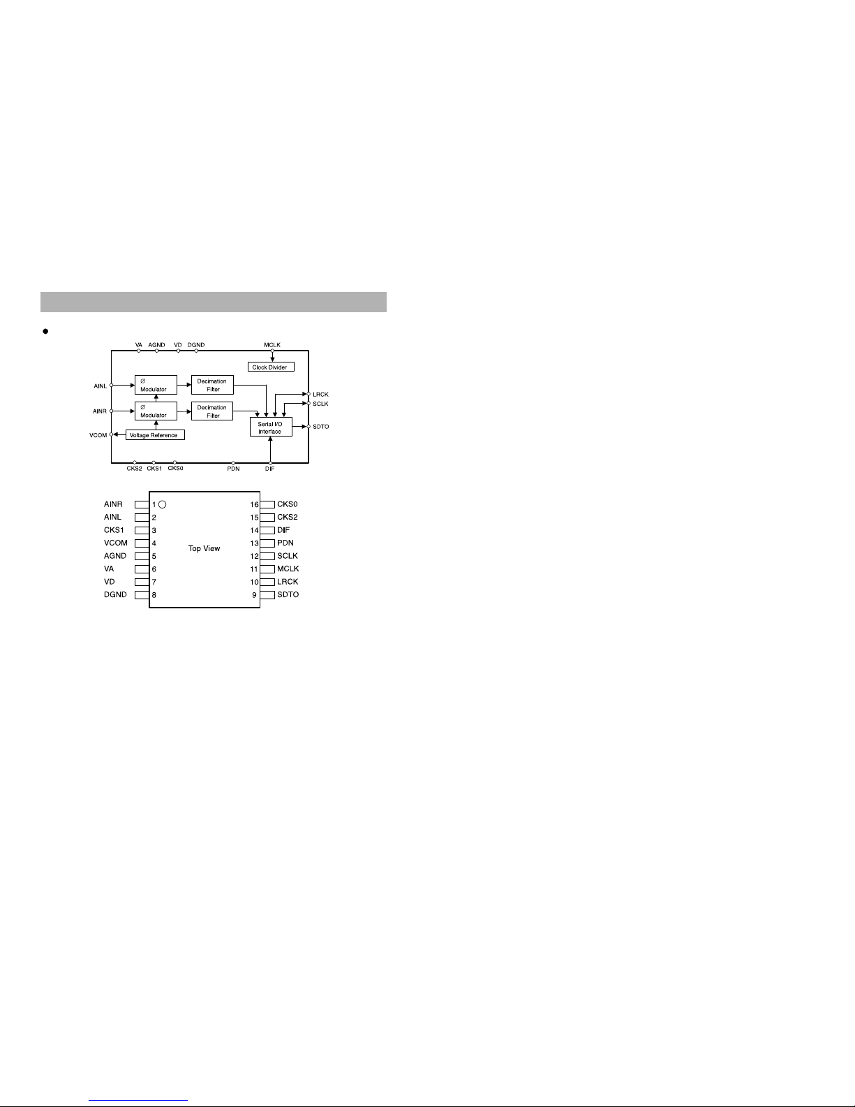
8. Internal Block Diagram of ICs
22
AK5381

9. Block Diagram
23

10. Wiring Diagram
24

11. Schematic Diagram
FRONT
25

11. Schematic Diagram
Mi-COM
26

11. Schematic Diagram
INPUT / VIDEO
27

11. Schematic Diagram
AMP
28

11. Schematic Diagram
POWER
29

12. Printed Circuit Diagram
30
[TOP View]
MAIN PCB [with DHC-100N Front]
This manual suits for next models
2
Table of contents


