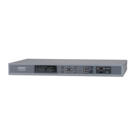
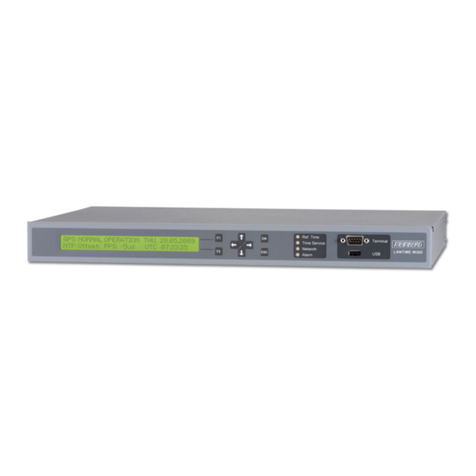
DCS 992 User manual

© 1999, 2000, 2001 dCS Ltd
All rights reserved. Reproduction of this manual in any manner whatsoever,
without the written permission of dCS1is strictly forbidden. Additional copies of
this manual may be obtained from dCS.
Information contained in this manual is subject to change without notice, and
whilst it is checked for accuracy, no liabilities can be accepted for errors.
1dCS Ltd is Data Conversion Systems Ltd. Company registered in England No. 2072115
dCS 992
Master Clock
User Manual
Software version 2.0x
January 2001

dCS 992 User Manual Manual for Software Version 2.0x
dCS Ltd January 2001
Manual part no: DOC063992 iss 2A1 Page 2 file 063992ma2a1.pdf available from website
Contact dCS on + 44 1799 531 999 email to: more@dcsltd.co.uk
(inside the UK replace + 44 with 0) web site: www.dcsltd.co.uk
PRODUCT FEATURES
Formats x
PCM from 96 kS/s down to 32 kS/s
Formats supported are: AES/EBU (XLR and BNC), Dual AES (XLR) and SDIF-2
Word Clock (BNC).
Syncing x
Master mode or can sync to Word Clock or 1MHz, 5MHz or 10MHz GPS source,
in Slave mode or Learn mode. Sync to video option available
Functions x
High stability Master Clock
High speed or Dual AES (88.2 kS/s, 96 kS/s)
Multiple sample rates at the same time
Sync Link operation for multi-channel operation
Test Generator x
High quality signal generator.
Ease of Use x
Setups
Remembers last settings
Lockouts

dCS 992 User Manual Manual for Software Version 2.0x
dCS Ltd January 2001
Manual part no: DOC063992 iss 2A1 Page 3 file 063992ma2a1.pdf available from website
Contact dCS on + 44 1799 531 999 email to: more@dcsltd.co.uk
(inside the UK replace + 44 with 0) web site: www.dcsltd.co.uk

dCS 992 User Manual Manual for Software Version 2.0x
dCS Ltd January 2001
Manual part no: DOC063992 iss 2A1 Page 4 file 063992ma2a1.pdf available from website
Contact dCS on + 44 1799 531 999 email to: more@dcsltd.co.uk
(inside the UK replace + 44 with 0) web site: www.dcsltd.co.uk
CONTENTS
Product Features ................................................................................................2
Contents ..............................................................................................................4
About this Manual 5
Using Your dCS 992 For The First Time ............................................................6
Product Overview 6
What’s in the Box? 6
Mains Voltages 6
Installing Unit in a Rack 7
Getting Started 7
The Hardware – Architecture, Controls and Connectors ...............................8
dCS 992 Architecture 8
Rear Panel 12
Front Panel 14
The Software – the Menu .................................................................................18
Overview 18
The Menu Sequence 19
Menu Items 20
Remote Software ..............................................................................................26
Typical Applications.........................................................................................36
Using a dCS 992 to Sync a dCS 904 36
Using a dCS 992 to Sync a dCS 972 Upsampling a CD 37
Using a dCS 992 to Sync a dCS 972 Converting PCM to DSD 38
8 Channel P3D DSD Set Up with Monitoring 39
Operating Several Units on One Remote Chain 40
Multi-channel Sample Rate Conversion – with multiple sample rates out 41
Synchronising the dCS 992 to a GPS Clock 42
dCS 992 Technical Information.........................................................................44
Clocking 44
Calibration data from a typical unit 46
Digital Interface Specifications 48
AES3 (AES/EBU) Format 49
Power Consumption 52
Size, Weight and Operating Conditions 53
General Technical Information........................................................................54
PLL bandwidths 54
Options ..............................................................................................................58
Locking to Video Sample Rates 58
Mains Supply Voltage 58
Ordering Options for a New Unit 58
Having Your Options Changed 58
Maintenance and Support................................................................................60
Hardware 60
Software 61
Warranty 62
Hardware Update or Calibration 63
Safety and Electrical Safety 63
Troubleshooting ...............................................................................................64
Error Codes and Messages 64
Internal Device Error Codes 64
System Messages and Error Codes 65

dCS 992 User Manual Manual for Software Version 2.0x
dCS Ltd January 2001
Manual part no: DOC063992 iss 2A1 Page 5 file 063992ma2a1.pdf available from website
Contact dCS on + 44 1799 531 999 email to: more@dcsltd.co.uk
(inside the UK replace + 44 with 0) web site: www.dcsltd.co.uk
Troubleshooting Your System 66
dCS Support.......................................................................................................68
I wish .... 68
If You Need More Help 68
Other Information 68
Indexes and Software Version Numbers........................................................70
Definitions of Units 70
Abbreviations Used 70
Full Contents 71
Tables 74
Figures 74
Keywords and Phrases 75
Owner Registration Transfer 77
About this Manual
Note that there is a Full Contents at the end of the manual (page 71), along
with an index and lists of figures and tables.
References to other sections in the appear as Section Name page … . These
are hyperlinks in the softcopy version of the manual.
IMPORTANT! Important information is presented like this - ignoring this may cause you to
damage the unit, or invalidate the warranty.
The manual is designed to be helpful. If there are points you feel we could cover
better, or that we have missed out - please tell us.

dCS 992 User Manual Manual for Software Version 2.0x
dCS Ltd January 2001
Manual part no: DOC063992 iss 2A1 Page 6 file 063992ma2a1.pdf available from website
Contact dCS on + 44 1799 531 999 email to: more@dcsltd.co.uk
(inside the UK replace + 44 with 0) web site: www.dcsltd.co.uk
USING YOUR dCS 992 FOR THE FIRST TIME
Product Overview
The dCS 992 Master Clock is a high stability reference generator designed for
studio and live recording applications. It is designed to generate multiple outputs
at all commonly used sample rates, and it can output many different sample
rates simultaneously – allowing all the components of a multiple sample rate
digital audio system to be synchronised. The unit can operate in Master mode
from its own TCXOs2, or can slave to an external source, such as GPS. It can
“learn” the frequency of the external source, such that if this is interrupted for
any reason, the unit carries on seamlessly at the learnt frequency. If the external
reference reappears, the unit re-acquires lock in a very gradual and graceful
manner, such that any recording work is not interrupted.
The unit provides reference clocks to support systems sampling from 32kS/s to
192kS/s or DSD, via AES3 or SDIF-2 Word Clock formats. It also offers a
variety of “Superclock” options.
The unit is a sophisticated and powerful frequency synthesiser, with many
options. It may be controlled from its front panel, but we recommend that it be
set up using the Remote software, running on a PC – perhaps at base. These
setups may then be stored in the dCS 992, and recalled from its front panel
without a PC, perhaps on location. We strongly recommend this mode of
operation. The unit is pre-loaded at dCS with a small set of useful setups in safe
stores.
It is mains powered and is housed in a 1U (46mm) high 19” rack mounting case.
The unit is highly software based, and more functions and features will be added
from time to time. Software updates from dCS are free!3
What’s in the Box?
The contents of the box are at least:
dCS 992
User Manual
Control Summary
Mains Lead
2 Spare Fuses
Floppy disk with Remote software
Remote cable
Mains Voltages
The dCS 992 is shipped with its mains voltage preset for operation in the
destination country. The voltage is not intended to be changed by the user. If it
needs to be changed, contact your dealer or dCS.
2TCXO stands for Temperature Compensated Crystal Oscillator
3free if we email them, and you download from a PC COM port. Low cost if you ask us for EPROMs or other
media - we charge for media and handling.
dCS 992 User Manual Manual for Software Version 2.0x
dCS Ltd January 2001
Manual part no: DOC063992 iss 2A1 Page 7 file 063992ma2a1.pdf available from website
Contact dCS on + 44 1799 531 999 email to: more@dcsltd.co.uk
(inside the UK replace + 44 with 0) web site: www.dcsltd.co.uk
Installing Unit in a Rack
The unit is supplied with 19" rack mount ears fitted. If it is to be installed in a 19"
rack, the ears supplied may be used to locate it in the rack - but:
IMPORTANT! The ears should not be used as the only mechanical support. The unit should
rest on a shelf, or be supported in some other way. The ears will just locate
it in the rack, and stop it sliding forwards.
If the unit is not to be rack mounted, the ears may be removed.
Getting Started
Here’s what to do:
do this: Check the appropriate mains supply for your local mains is marked on the rear
panel.
do this: If it is, using the lead supplied, connect the unit to the mains - connect no other
leads at this stage - and switch on.
The 7-segment display will briefly show:
- - - - 4
and then the sample rate, for example:
9 6
do this:
do this: Connect an output (e.g. from Word Clock Out 1) to the Reference input of an
ADC or DDC in your system. If you lock a DAC to the Master Clock, ensure the
source driving the DAC is locked to it as well.
do this: Press the Sample Rate button (left hand end button) repeatedly until the sample
rate you want is displayed.
do this: If your system is running Dual AES at 88.2 or 96kS/s, press the Output Format
button until the indicator beside it changes to 2, otherwise set it to 1. Dual AES
requires only one Reference connection.
Set up like this, the dCS 992 will operate in Master mode, and the system it is
connected to will (have to) lock to it. You should have audio.
Note that all the outputs are active simultaneously on the dCS 992 and may all be
connected to external equipment simultaneously if required.
Now you will need to familiarise yourself with how the front panel controls and
the menu system work.
do this: Read the short section The Software – the Menu on page 18 so you know how
the buttons and menu work.
You may also find it convenient to refer to the Control Summary sheet while
you are getting to know the unit.
If the unit does not behave the first time you power up – contact your dealer, or
dCS.

dCS 992 User Manual Manual for Software Version 2.0x
dCS Ltd January 2001
Manual part no: DOC063992 iss 2A1 Page 8 file 063992ma2a1.pdf available from website
Contact dCS on + 44 1799 531 999 email to: more@dcsltd.co.uk
(inside the UK replace + 44 with 0) web site: www.dcsltd.co.uk
THE HARDWARE – ARCHITECTURE, CONTROLS AND CONNECTORS
dCS 992 Architecture
The dCS 992 is capable of generating some extremely complex clocking
arrangements. To help understand some of its features, the architecture is
described below.
TCXO
Control
TCXO 1
TCXO 2
TCXO 3
optional
TCXO 4
optional
AGEN 1 AES 1
output
AGEN 2 AES 2
output
AGEN 3 AES 3
output
AGEN 4 AES 4
output
F , O, M, S
s
AES generators
Drag and drop
selection
AES3 outputs
To SGENs (1-6)
F , O, M
s
F , O, M
s
F , O, M
s
Figure 1 – Internal clocking, AGEN generators and AES3 output
matrix
Fs = Sample Rate, Φ= Phase, M = AES3 message, S = Signal (tone)

dCS 992 User Manual Manual for Software Version 2.0x
dCS Ltd January 2001
Manual part no: DOC063992 iss 2A1 Page 9 file 063992ma2a1.pdf available from website
Contact dCS on + 44 1799 531 999 email to: more@dcsltd.co.uk
(inside the UK replace + 44 with 0) web site: www.dcsltd.co.uk
TCXOs and AGENs
The unit contains several TCXOs, only one of which is active at any time. The
active one is temperature compensated and controlled by a DSP. Its output is
routed to four independent4AGEN AES3 generators (AGEN 1–4). The AES 1
output is always connected to AGEN 1 – all other AES3 outputs (AES 2 - 4)
may be connected to any AGEN – they can all be driven by AGEN 1, or they can
have one each, or anything in between. AGENs can be programmed for sample
rate, output phase, AES3 message content, and (in the case of AGEN 1) the
audio signal it carries.
AGEN 1 is special – its output sample rate determines which TCXO is used. It
will have the lowest jitter. If other AGEN sample rates are set to integer
multiples or sub-multiples of AGEN 1’s, then they have negligible jitter. If,
however, they are set to sample rates with complex relationships to AGEN 1,
then the DDS used to generate them will dither the transition times, generating
jitter. If, for example, AGEN 1 is set to 48kS/s, and AGEN 2 is set to 44.1kS/s,
then the output of AGEN 2 will have about 44 nsecs of jitter on its edges.
Although this sounds a lot, it is high frequency noise shaped jitter that is easily
rejected by a receiving PLL, and is well within the requirements of the AES3
data eye spec.
AGEN 1 is also special in that it has a tone generator associated with it, so that
it can have an audio tone superimposed on it. The other AGENs cannot.
Can be
programmed for
AGEN 1 AGEN 2 AGEN 3 AGEN 4
Sample Rate (Fs) yes yes yes yes
Phase (Φ) yes yes yes yes
AES3 Message (M) yes yes yes yes
Signal from tone
generator (S)
yes No – digital
silence
No – digital
silence
No – digital
silence
Table 1 – AGENs, and what can be programmed
4There are some restrictions on independence to do with 32kS/s operations

dCS 992 User Manual Manual for Software Version 2.0x
dCS Ltd January 2001
Manual part no: DOC063992 iss 2A1 Page 10 file 063992ma2a1.pdf available from website
Contact dCS on + 44 1799 531 999 email to: more@dcsltd.co.uk
(inside the UK replace + 44 with 0) web site: www.dcsltd.co.uk
SGENs
SGEN 1
SDIF 1
output
F , O
s
SDIF generators SDIF outputs
From TCXOs
SDIF 7
output
SGEN 2
SDIF 2
output
F , O
s
SDIF 8
output
SGEN 3
SDIF 3
output
F , O
s
SDIF 9
output
SGEN 4
SDIF 4
output
F , O
s
SDIF 10
output
SGEN 5
SDIF 5
output
F , O
s
SDIF 11
output
SGEN 6
SDIF 6
output
F , O
s
SDIF 12
output
Figure 2 – SGEN generators and Word clock outputs
The unit also contains six independent SGEN word clock generators, that are
routed (with no flexibility) to pairs of SDIF-2 (BNC) word clock outputs. The
signals coming out of these can be independent, or linked to AGEN 1. Multiples
of the normal word clock output rates can be selected (“Superclocks”) up to
12.288 MHz (or 11.2896 MHz – the 256 Fs superclock).
Sync Link
The dCS 992 is capable of Sync Link operation with dCS 972s – see Figure 14 on
page 41. This operates for all supported sample rates of 44.1kS/s or higher5(so
48kS/s, 88.2kS/s, 96kS/s, 176.4kS/s, 192kS/s are all okay), and needs no
additional setting up.
5If you need it to operate at other frequencies, contact dCS

dCS 992 User Manual Manual for Software Version 2.0x
dCS Ltd January 2001
Manual part no: DOC063992 iss 2A1 Page 11 file 063992ma2a1.pdf available from website
Contact dCS on + 44 1799 531 999 email to: more@dcsltd.co.uk
(inside the UK replace + 44 with 0) web site: www.dcsltd.co.uk

dCS 992 User Manual Manual for Software Version 2.0x
dCS Ltd January 2001
Manual part no: DOC063992 iss 2A1 Page 12 file 063992ma2a1.pdf available from website
Contact dCS on + 44 1799 531 999 email to: more@dcsltd.co.uk
(inside the UK replace + 44 with 0) web site: www.dcsltd.co.uk
Rear Panel
AES 1 AES 2 AES 3 AES 4
AES/EBU Outputs
Wordclock Outputs
1 2 3 4 5 6
7 8 9 10 11 12
External
Sync Remote
In
Loop
Out
Mains Fuse (2AT) On Off
V 50-60Hz
Disconnect mains
before removing cover
Figure 3 – Rear Panel
All input and output connectors are mounted on the rear panel. Individual
connectors are clearly identified by the panel legend. Viewed from the rear from
left to right, the connectors are as follows:
AES 1, 2, 3& 4 Clock Outputs 3 pin XLR male (4 off)
These may be used as four independent AES/EBU outputs in single wire format
or 2 Dual AES pairs (AES 1 & 2and AES 3 & 4) in two wire format.
In master clock applications, any of the 4 outputs may be used as a reference
source since the (single) AES Reference Input on the destination equipment will
ignore the Channel 1 / Channel 2 message. While using the Test Generator in
Dual AES mode, these outputs must be used in pairs to drive a Dual AES input
for correct operation.
The outputs may be tied together, or independently programmed.
SDIF-2 Word Clock 1 – 12 Outputs BNC (12 off)
12 independent Word Clock outputs. They may be programmed in pairs, or
linked together.
External Sync Input BNC
The unit may be slaved to an external Word Clock or a 1MHz, 5MHz or 10MHz
GPS or laboratory reference connected to this input. The unit auto detects
1MHz, 5MHz or 10MHz.
Remote In & Loop Out 9 pin D type male (2 off)
These are for use with the Windows™ - based Remote software. If this is in use,
connecting Remote In to a COM port on a PC running the Remote Control
program will allow the unit to be controlled by the PC. Loop Out may be
connected to another suitably equipped dCS unit, allowing several units to
controlled by the same PC. The Remote software will allow the unit to be
software upgraded without removing the lid by downloading new software via the
Remote In connector.
Connect up Remote ports using a 9-way screened cable, fitted with 9-way ‘D’-
type female connectors at each end, wired pin 1 to pin 1, pin 2 to pin 2, etc. The
same type of cable can be used unit to unit as com port to first unit. Suitable
cables are available from dCS.
Mains Supply 3 pin IEC (CEE22)
Switched, fused and filtered IEC mains connector.

dCS 992 User Manual Manual for Software Version 2.0x
dCS Ltd January 2001
Manual part no: DOC063992 iss 2A1 Page 13 file 063992ma2a1.pdf available from website
Contact dCS on + 44 1799 531 999 email to: more@dcsltd.co.uk
(inside the UK replace + 44 with 0) web site: www.dcsltd.co.uk
Additional Information
As well as connectors, the rear panel displays the following information about
the unit, near the mains supply connector:
Mains Voltage The actual voltage setting supplied.
Model Number dCS 992
Manufacturers Name and Country of origin (dCS Ltd, UK)
There will be a label on the underside of the unit that contains a number such as
992-4B1-6B2-2A1-3A2-12345. This is the serial number, but it also contains vital
configuration information. We will need this number (all of it) to give you support
over the phone, or to ship you software updates.

dCS 992 User Manual Manual for Software Version 2.0x
dCS Ltd January 2001
Manual part no: DOC063992 iss 2A1 Page 14 file 063992ma2a1.pdf available from website
Contact dCS on + 44 1799 531 999 email to: more@dcsltd.co.uk
(inside the UK replace + 44 with 0) web site: www.dcsltd.co.uk
Front Panel
Master Clock
dCS 992
Data Conversion Systems
24
9
dCS
BIT
kHz
Sample
Rate Menu Test
Generator Parameter Calibrate Master Slave Output
Format
MENU
Step Set kS/s
Sample Rate
6
Figure 4 – Front Panel
The dCS 992 uses a combination of front panel buttons for frequently changed
functions and a step through menu for features you might set and forget.
Sample Rate Button x
Press the Sample Rate button repeatedly to cycle through the sample rates in
the order:
96 ... 88.2 ... 48 ... 44.1 ... 32 ... 96 ... etc.
Do not press the button too fast as a delay is built in to the software. The sample
rate selected is shown on the LED display in the centre of the panel.
Menu Button x
Press the Menu button to open the Function Menu, see The Software – the
Menu on page 18. Press again to step through the menu pages.
Test Generator, Parameter, ↓
↓↓
↓and ↑
↑↑
↑Buttons
These buttons control the high quality sine wave generator.
do this: Press the Test Generator button – Off will be displayed for a few seconds.
Quickly press Test Generator again to turn it On.
At power up, the generator is always set to Off, 1kHz and -18dB0 to prevent
damage to your ears or loudspeakers.
do this: Press the Parameter button to select Level adjustment. Press the ↑
↑↑
↑button
repeatedly to increase the tone level in 0.1dB steps up to a maximum of 0.0dB0
(full scale). Press the ↓
↓↓
↓button repeatedly to reduce the tone level in 0.1dB steps
down to a minimum of –120.0dB0. Hold down the ↓
↓↓
↓or ↑
↑↑
↑buttons to change level
more quickly, the rate accelerates.
do this: Press the Parameter button again to select Frequency adjustment. Press the ↑
↑↑
↑
button repeatedly (or hold it down) to increase the tone frequency in 0.1kHz
steps from 1kHz to a maximum of 48% of the sample rate. Press the ↓
↓↓
↓button
repeatedly (or hold it down) to reduce the tone frequency in 10Hz steps from
1kHz to 100Hz. Below 100Hz (0.1kHz), the step size changes to 1Hz until the
minimum tone frequency of 1Hz (0.001kHz) is reached.
If a number between 0.0 and –120.0 is displayed, it is a Level. If a number
between 0.001 and 47.0 is displayed, it is a Frequency. If in doubt, press the
Parameter button to see what is selected.
IMPORTANT! If the Output Format is set to 2, the Test Generator output should only be
taken from the AES 1 & 2pair or the AES 3 & 4pair to a Dual AES input.
There is no data (and so no tone) on SDIF-2 Word Clock outputs.

dCS 992 User Manual Manual for Software Version 2.0x
dCS Ltd January 2001
Manual part no: DOC063992 iss 2A1 Page 15 file 063992ma2a1.pdf available from website
Contact dCS on + 44 1799 531 999 email to: more@dcsltd.co.uk
(inside the UK replace + 44 with 0) web site: www.dcsltd.co.uk
The ↑
↑↑
↑button may also be used to step through menu pages. See Entering the
Menu on page 18 for details.
Calibrate indicator x
This will light up after the unit has been under power for 6 months to warn you
that the calibration guarantee has expired. The unit will continue to operate and
the drift in sample frequency caused by crystal ageing may not be important in
your application. To have your dCS 992 re-calibrated, please contact dCS. You
may be able to re-calibrate your unit locally.
Menu Set Button Menu Set
Press the Menu Set button to change a menu option, see The Software – the
Menu on page 18.
Master/Slave Button Menu Down
The Master/Slave button sets the clocking mode (master, slave, or learn
modes) , or in the menu acts as the Down button.
Outside the menu, pressing it cycles through:
Master … Slave … Learn … Master …
In Master mode, the calibrated voltage controlled crystal oscillators (TCXOs)
inside the unit generate an accurate sample rate. The LED labelled Master will
be lit to indicate this.
Slave mode - if an accurate standard reference source, such as GPS6source or
an accurate SDIF-2 Word Clock source is available, this may be connected to
the External Sync connector. To slave the unit to the External Reference, press
the Master/Slave button. The unit will attempt to lock to the reference source -
this will take a few seconds. When lock is achieved, the Slave LED will light up
brightly and the Master LED will turn off. If the reference source is lost, the unit
will revert to Master mode, unless it is in …
Learn mode – press the Master/Slave button again. This mode slaves to the
incoming reference, but if the reference is lost, the unit carries on at the learnt
frequency.
To return to Master mode, press the Master/Slave button again.
If the Auto-Slave menu option is turned On the unit will automatically slave
when a suitable reference is connected, see A-SL – Autoslave ON/Off, page
22.
The Master/Slave button is also used to decrement the setting of the Offset
and the RS232 address.
Output Format Button Menu Up
Pressing the Output Format button toggles the output format between Single
AES at Double speed and Dual AES at Standard speed, if the sample rate is set
to 88.2 or 96kS/s. In the menu, it also operates as the Up button.
6GPS stands for Global Positioning System

dCS 992 User Manual Manual for Software Version 2.0x
dCS Ltd January 2001
Manual part no: DOC063992 iss 2A1 Page 16 file 063992ma2a1.pdf available from website
Contact dCS on + 44 1799 531 999 email to: more@dcsltd.co.uk
(inside the UK replace + 44 with 0) web site: www.dcsltd.co.uk
Single AES is the only option available if the sample rate is set to 32, 44.1 or
48kS/s so the Output Format button has no effect.
As the Up button it is also used in the menu to increment the setting of the
Offset and the RS232 address, and other parameters that need adjusting.
Mode Display x
The single digit LED mode display to the right of the Output Format button
shows the output format:
Display Output Format
1Single AES
2Dual AES
Table 2 – Output Data format indication, higher sample rates
When the Output Format is selected, the main display briefly shows the format
code:
A1 for Single AES, Standard speed encoding.
b1 for Single AES, Double speed encoding.
b2 for Dual AES, Standard speed encoding.
Sample Rate Display x
The main display generally shows the sample rate in kS/s. When other
parameters are set, it briefly shows the new setting (Mode, Tone Level, Offset,
etc.) then reverts to displaying sample rate. In the case of an error condition, it
will display an error message.
If the unit is being slaved, the display shows the following:
xxx the sample rate, in kS/s (32, 44.1, 48, 88.2 or 96).
b xxx slaved to the External Sync input.
o xxx in Learnt mode, with external reference lost.
d xxx temporary display during locking – the unit thinks it
knows what the input reference frequency is, and is
attempting to lock to it.
Important error messages are given below – a full list is given in the section
Error Codes and Messages on page 64.
BadFs The clock source is not in pull in range, or is poorly
formatted. The unit cannot lock to it.
Err.xy An error has been detected.
Hot The unit is overheating, probably due to inadequate
ventilation. Please check positioning and cooling.
Ouch The “Hot” warning has been ignored and the unit is
getting so hot damage may follow.
(blank If the display is blank for any significant period, turn
the unit off for 10 seconds then back on. If this
does not solve the problem, please contact your
distributor or dCS.
The display is also used for Menu options.

dCS 992 User Manual Manual for Software Version 2.0x
dCS Ltd January 2001
Manual part no: DOC063992 iss 2A1 Page 17 file 063992ma2a1.pdf available from website
Contact dCS on + 44 1799 531 999 email to: more@dcsltd.co.uk
(inside the UK replace + 44 with 0) web site: www.dcsltd.co.uk

dCS 992 User Manual Manual for Software Version 2.0x
dCS Ltd January 2001
Manual part no: DOC063992 iss 2A1 Page 18 file 063992ma2a1.pdf available from website
Contact dCS on + 44 1799 531 999 email to: more@dcsltd.co.uk
(inside the UK replace + 44 with 0) web site: www.dcsltd.co.uk
THE SOFTWARE – THE MENU
Overview
The dCS 992 has many other functions that either need to be accessed only
occasionally, or are informative in nature. These functions can be accessed
either by the Remote software, running on a PC and connected to the unit by an
RS-232 link - or (in most cases) by the Menu. For the more complex functions,
we strongly recommend use of the Remote software – this can be used to set
up complex options, and then store these in user stores in the unit (stores 1 –
9). The complex stored setups can then be easily recalled without use of a PC
or computer connection – perhaps on location. The Remote software is covered
in section Remote Software on page 26.
If a function is set by the menu or the remote, the unit remembers it, and it will
be set this way for ever (or until you set it to something different). In the case of
an unwanted complex setup be remembered, the unit can easily be reset to a
known clean condition by recalling one of the dCS preset stores (Stores A - E).
Store A is the simplest setup. The menu (and Remote) allows access to some
information-only items. When called up, these are displayed for a time, then the
display reverts to normal.
Menu buttons are indicated by white text on the front panel. There are for:
Step otherwise Overload Level
Set otherwise ADC/Data
Down otherwise Master/Slave
Up otherwise Output Format
Entering the Menu x
There are two ways to enter the Menu:
•Press the Menu button once, or
•Hold down the menu Step button and press the menu Set button once.
(This might make one-handed operation easier.)
The display will show:
Func
Moving through the Menu x
Press the Menu button again (or the Menu Step button if you prefer) within 5
seconds to step through the Menu items listed below. When you reach the
required item, press the Menu Set button to change its setting. This either
toggles the previous state, or causes an information function to read out, or
selects a numerical setting (Offset and RS232 address). For a numerical setting,
press the Down button to reduce it by 1 digit or the Up button to increase it by 1.
If no changes are made in 5 seconds, the unit exits the Menu. When one item
has been set, press the Menu button again if you wish to continue cycling
through the Menu.
There is a knack to doing this easily – once it has been gained, it becomes very
easy to use.

dCS 992 User Manual Manual for Software Version 2.0x
dCS Ltd January 2001
Manual part no: DOC063992 iss 2A1 Page 19 file 063992ma2a1.pdf available from website
Contact dCS on + 44 1799 531 999 email to: more@dcsltd.co.uk
(inside the UK replace + 44 with 0) web site: www.dcsltd.co.uk
The Menu Sequence
Sample Rate Func Test Generator Parameter
Sets the output
sample rate
Opens the
Function Menu
and steps
through it
Turns the tone
generator on
Selects tone Level
or Frequency for
adjustment
Adjusts Test
Generator
parameters
96kS/s Off Level -120...-18...0dB
88.2kS/s On Freq
48kS/s 1Hz...1k...0.48Fs
44.1kS/s
32kS/s
Menu Set Master / Slave Output Format
Selects a Menu
item or option
Slaves the unit to
the Test input
(when Wordclk
is connected)
Selects single or
dual AES (88.2 or
96kS/s only)
Master 1 / A (32 to 48k)
Slave 1 / b1
Learn 2 / b2
To access the Function Menu, press the Menu button.
To step through the Menu items, press the Menu button repeatedly.
To select an item or one of its options, press the Menu Set button.
Use Menu Up and Menu Down buttons to alter RS232 address and Offset.
To exit the Function Menu, either select the End item or wait five seconds.
Func Issue Offst Read Test 7 - Seg
Start of the
Function Menu
Displays the
fitted software
issue number
Offsets the
sample rate in
0.05ppm steps
Reads a
stored setup
(user store 1-9
dCS store A-E)
Runs a displa
y
self
test routine
Disables the 7-
segment display
when idle.
v 2.0x +5.00...0...-5.00 Stor1 - 9 On
StorA - E Off
RS232 S - No Part Facs Phone Heat
Displays and sets
the unit's RS232
address
Displays the
control PCB
serial number
Displays the
control PCB
part number
Displays dCS
fax number
Displays dCS
telephone number
Displays the
internal
temperature
0 ... 99 0002-540-?-? dCS002540? Fahrenheit
Celsius
A-SL Loc rSout AES G AES O SDIF
Automatically
slaves when ref
input available
Locks out the
front panel
controls
Enables the
calibration data
output
Sets Fs & phase
of AGEN 1 - 4
generators
Selects AES3
outputs to AGEN 1
- 4 generators
Sets Fs & phase
of SGEN 1 - 4
generators
See manual See manual See manual
Off Off Off It is easier to use the Windows Remote to control these 3 features
On On On
End
Exits the Function
Menu
Figure 5 – Menu Sequence and Control Summary

dCS 992 User Manual Manual for Software Version 2.0x
dCS Ltd January 2001
Manual part no: DOC063992 iss 2A1 Page 20 file 063992ma2a1.pdf available from website
Contact dCS on + 44 1799 531 999 email to: more@dcsltd.co.uk
(inside the UK replace + 44 with 0) web site: www.dcsltd.co.uk
Menu Items
Issue – Software Issue x
Displays the software issue when Menu Set is pressed.
Offst – VCXO Frequency Trim x
Trims the appropriate TCXO frequency in master mode, by up to ±5ppm in
0.05ppm steps. Press the Down button to reduce the value or the Up button to
increase the value. The Offset for both VCXO’s is remembered.
Read – Setup Unit from a Store x
Reads back the content of a store, and sets the unit up accordingly. There are
nine user programmable stores (Stores 1-9) and five dCS pre-loaded stores
(Stores A-E). The dCS pre-loaded stores may not be overwritten – the user
stores may be loaded by the user when setting up the unit with the remote from
a PC. Note that there is no facility to load the stores without using a PC – the
possibility of an eroneous setup is too high.
Stores A or Bmay be regarded as a factory reset – they set the unit up for
straight forward 44.1kS/s or 48kS/s operation. Press menu Step to scroll
through the stores (1-9, then A-E) then Set to select one.
The intended mode of use is that the unit be set up using the Remote software
running on a PC, and then the setup stored. The unit can then recall the setup
either in the studio or on location – even if it is complex. This way, set ups only
have to be worked out once.
The contents of Stores A-E is pre-loaded as in Table 3 below.
Table of contents