ddtop MFTC Series User manual

1/ 12
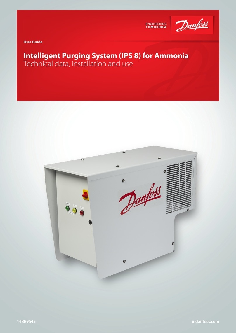
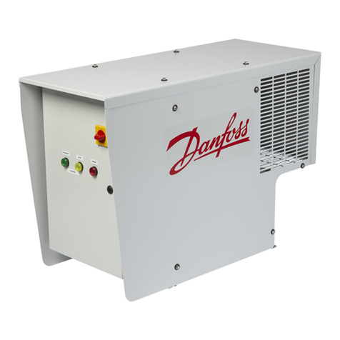
WWW.DDTOP.COM
MFTC
SERIES PURGE DEVICE
Operation Manual
MTFC-DT-JS-1040-2020(A)

2/ 12
WWW.DDTOP.COM
Preface
Thank you for choosing the products of Dandong TOP Electrical Appliance (Group) Co.
This instruction manual provides you with important information on installation, connection and
commissioning as well as for maintenance, troubleshooting and storage. Please read it carefully
before installation and commissioning and keep it close to the instrument as an integral part of the
product, so that you can refer to it at any time.
You can download this instruction manual by entering the version number at www.ddtop.com.
If the instrument is not operated in accordance with these instructions, the protection provided by
the instrument may be impaired.
Trademark, Copyright and Restriction Instructions
Dandong Top Electronics Instrument (Group) Co., Ltd.®, Dandong Top Pump Co., Ltd.®, DDTOP®
are registered trademarks of the company.
The performance specifications of this instrument are effective from the date of publication and are
subject to change without notice. Dandong Top Electronics Instrument (Group)Co., Ltd. reserves the
right to modify the products described in this manual at any time without notice.
Quality Assurance
Dandong Top Electronics Instrument (Group) Co., Ltd. guarantees all LBTC Positive Displacement
Rotary Vane Flow Meter to be free from defects in materials and manufacturing processes within
one year from the date of delivery.
During the warranty period, Dandong Top Electronics Instrument (Group) Co., Ltd. is responsible for
repairing or replacing the equipment free of charge for the buyer (or owner) if the product is
returned with quality problems and the claim made is determined to be covered by the warranty
after inspection by the manufacturer.
Dandong Top Electronics Instrument (Group) Co. Ltd. shall not be liable for improper use of the
equipment, labor claims, direct or subsequent damage, or costs arising from the installation and use
of the equipment. Dandong Top Electronics Instrument (Group) Co., Ltd. does not provide any
warranty, either express or implied, except for special written warranty certificates for certain
products of Dandong Top Electronics Instrument (Group) Co., Ltd.

3/ 12
WWW.DDTOP.COM
Quality
Dandong Top Electronics Instrument (Group) Co., Ltd. has passed the ISO9001 quality system
certification. The whole production process is carried out in strict accordance with the provisions of
the quality system to provide the strongest guarantee for the quality of products and services.

4/ 12
WWW.DDTOP.COM
目录
1 安全提示 ...................................................................................................................错误!未定义书签。
1 Safety Tips .................................................................................................................................................6
1.1 爆炸可能会导致死亡或严重伤害。 ...................................................................错误!未定义书签。
1.1 An explosion may cause death or serious injury. ............................................................................. 6
1.2 过程泄漏可能导致严重伤害或死亡。...............................................................错误!未定义书签。
1.2 Serious injury or death may result from process leakage.............................................................. 6
1.3 不遵守安全安装准则可能导致死亡或严重受伤。........................................错误!未定义书签。
1.3 Failure to comply with safety installation guidelines may result in death or serious injury.6
2吹扫装置概述 ............................................................................................................错误!未定义书签。
3结构和测量原理 ........................................................................................................错误!未定义书签。
3 Structure and measuring principle .........................................................................................................6
3.1 入口吹扫装置测量原理-图1................................................................................错误!未定义书签。
图1................................................................................................................................错误!未定义书签。
3.2 出口吹扫装置测量原理-图2................................................................................错误!未定义书签。
3.2 Outlet Purge Device Measuring Principle -Figure 2........................................................................ 8
图2................................................................................................................................错误!未定义书签。
Figure 2 Schematic Diagram of the Outlet Purge Device Measurement Principle................................8
4产品特点 ....................................................................................................................错误!未定义书签。
5技术指标 ....................................................................................................................错误!未定义书签。
5 technical parameters...................................................................................................................................9
6典型应用 ....................................................................................................................错误!未定义书签。
6 Typical Applications...................................................................................................................................9
Figure 4 Diagram of Guided Wave Radar Installation Location in Conical Bottom Tank .........................10
7吹扫装置安装注意事项.............................................................................................错误!未定义书签。
7 Precautions for installation of Purge Device............................................................................................10
8吹扫装置的操作要点.................................................................................................错误!未定义书签。
8 Key points for the operation of the purge device.....................................................................................11
9维护与保养.................................................................................................................错误!未定义书签。
9 Maintenance and repair............................................................................................................................11
9.1 定期检查项目 ............................................................................................................错误!未定义书签。
9.1 Periodic inspection items........................................................................................................................11
9.2 故障诊断......................................................................................................................错误!未定义书签。
9.2 Troubleshooting.........................................................................................................................................12
10 拆卸 .........................................................................................................................错误!未定义书签。
10 Disassembly ..........................................................................................................................................12
10.1 警告 ...........................................................................................................................错误!未定义书签。
10.1 Warnings....................................................................................................................................................12

5/ 12
WWW.DDTOP.COM
10.2 废物清除 ................................................................................................................. 错误!未定义书签。
10.2 Waste removal .........................................................................................................................................12

6/ 12
WWW.DDTOP.COM
1 Safety Tips
Unauthorized modification or alteration of the product is expressly forbidden for safety reasons.
Repair or replacement is permitted only with parts specified by the manufacturer.
1.1 An explosion may cause death or serious injury.
When installing equipment in explosive atmospheres, always follow applicable local, national, and
international standards, codes, and procedures. Ensure that equipment is installed in accordance
with intrinsically safe or non-flammable site work procedures.
1.2 Serious injury or death may result from process leakage.
If the process seal is damaged, leakage of media may occur at the connection.
1.3 Failure to comply with safety installation guidelines may result in death or serious injury.
All operations described in these instructions must be performed by trained and qualified or
end-user appointed personnel.
2 Overview of the blowing unit
MTFC10 series purge device adopts variable area flow meter and constant flow valve to form a
purge device, which realizes flow measurement and stable output in occasions of pressure
fluctuation. The device adopts all-metal structure, with the characteristics of small volume, small
pressure loss and large range ratio (10:1). It can be used in various industries in complex and harsh
environments, as well as the flow measurement and process control of micro flow, low flow rate,
and various harsh medium conditions. It is especially suitable for measuring turbid, opaque or
corrosive fluids, or flow measurement with vibration occasions. According to different user needs
and different occasions, there are a variety of measurement forms for users to choose from.
According to the output form, there are local indication type and remote transmission type.
According to the constant-flow valve form, there are inlet constant flow valve type, export constant
flow valve type.
3 Structure and measuring principle
3.1 Inlet Purge Device Measuring Principle-Figure 1

7/ 12
WWW.DDTOP.COM
Figure 1 Schematic Diagram of the Inlet Purge Device Measurement Principle
(1)P2A+P1a+f
As shown in the Purge Device Schematic Diagram: (RH Inlet Constant Flow Valve)
Elastic diaphragm is subjected to upward force:
(2)P3A+P2a+F
When the pressure is balanced,that is (1) = (2)
(3)P2A+P1a+f= P3A+P2a+F
Elastic diaphragm is subjected to downward force:
(4)P2-P3=(F-f)/A-(a/A)(P1-P2)
Since the flow rate is determined by the pressure on both sides of the diaphragm, P2-P3, the
following formula can be obtained by the formula in (3):
Since A>>a, (a/A) (P1-P2) is negligible, and F, f, and A are constant values, so P2-P3 is constant
value, then the flow rate will not change due to the pressure change at the inlet.
When the medium is an incompressible liquid, the RE inlet can be applied to the outlet pressure
variation. For (4), P1 is constant and P3 is changing, so P3 becomes P3+△P,P2 becomes P2+△P, so
P2-P3=C is a constant value.

8/ 12
WWW.DDTOP.COM
3.2 Outlet Purge Device Measuring Principle -Figure 2
Figure 2 Schematic Diagram of the Outlet Purge Device Measurement Principle
P2A+P3a+F
As shown in the Purge Device Schematic Diagram: (CH Outlet Constant Flow Valve)
Elastic diaphragm is subjected to downward force:
P2A+P3a+F
P2A+P3a+F= P1A+P2a
Elastic diaphragm is subjected to upward force:
P1A+P2a
When the pressure is balanced,that is (1) = (2)
P2A+P3a+F= P1A+P2a
P1-P2=F/A-(a/A)(P2-P3)
Since the magnitude of the flow depends on the difference P1-P2 of the pressure regulator
diaphragm, we can get by (3):
P1-P2=F/A- (a/A) (P2-P3)
In the case of incompressible liquids, the CH outlet constant flow valve can be used for inlet
pressure changes. For (4), P2 is constant and P1 is variable, so P1 becomes P1+△P, P2 becomes
P2+△P, so P2-P3=C is a constant value.
In the formula above:
A: Diaphragm cross-sectional area
A: Control valve spool (ball) cross-sectional area.
F/f: Spring pressure (spring force).
△P: Change in P2 or P3

9/ 12
WWW.DDTOP.COM
4 Product Features
1. Single-/ double-/ multiple-channel forms (optional)
2. Single-table installation, panel installation (optional)
3. NPT 1/4, ferrule, thread, flange connection (optional)
4. 6mm, 8mm, 10mm, 12-25mm pipeline (optional)
5. Suitable for corrosive media or environments
6. Both mechanical and digital options available
7. Can be used where there are pressure fluctuations in the inlet and outlet.
5 technical parameters
1. Measurement range: water (20°C) (0.3 to 100)L/h; air (20°C 101325Pa) (1.2 to 3400)L/h
2. Range ratio: 10:1
3. Accuracy level: Level 4
4. Maximum working pressure: 2.5 MPa (can be increased as required)
5. Temperature of the medium: -40 to +150°C
6. Ambient temperature: -25~+70℃
7. Connection: 1/4" NPT female thread or Φ6 (Φ8) ferrule connection or horizontal/vertical
connection according to customer's requirement.
8. Limit alarm: 1 to 2 alarm switches (optional)
9. Dimensions: Horizontal mounting center distance: 70mm
6 Typical Applications
When using the orifice plate to measure the
flow of corrosive liquids or liquids containing
solid particles, a double-mounted Purge
Device is used to continuously and
quantitatively blow air into the pressure ports
before and after the orifice plate to ensure
that corrosive liquids or liquids containing
solid particles do not flow into the pressure
guide tube of the differential pressure meter
or differential pressure transmitter.
As shown in the diagram above, one
main air supply is divided into multiple
branch air supply sources. If one or more
of the branch sources stops supplying or
adjusts the flow, a change in the main
source pressure will occur. An inlet
(primary pressure) pressure change
control type purge device maintains its
output flow constant.

10 / 12
WWW.DDTOP.COM
Figure 4 Diagram of Guided Wave Radar Installation Location in Conical Bottom Tank
7 Precautions for installation of Purge Device
1. Please select the appropriate location for installation of the flow Purge Device to ensure easy
adjustment, cleaning, and removal of the Purge Device.
2. As the float flow rate of the Purge Device is accompanied by a magnetic coupling drive, it is
necessary to ensure that the disturbing magnetic field generated by other working equipment
does not affect the measurement results of the flow meter.
3. When installing, ensure that the Purge Device is stable and, if necessary, fitted with a mounting
bracket in an appropriate location.
4. The installation dimensions shall not exceed the given dimensions by too much or too little in
order to avoid tensile or compressive forces acting on the Purge Device.
5. When the liquid medium contains ferromagnetic particles, a magnetic filter must be installed
before the instrument.
By detecting the static pressure of each
section of the blast furnace body and
calculating the air permeability resistance
index to forecast the furnace condition, so as
to take timely measures to ensure normal
smelting, thus achieving the purpose of
increasing production and energy
conservation.
This is a method of detecting the level of
liquid by measuring the back pressure at the
end of the blowpipe. The Purge Device, which
uses the outlet (secondary pressure) pressure
change control type, continuously and
quantitatively blows gas into the
measurement object. A differential pressure
transmitter or manometer is usually used to
display the liquid level.

11 / 12
WWW.DDTOP.COM
6. To ensure proper operation of the instrument, the medium flowing through the instrument
must be clean and free of impurities such as dust particles. Although our company installs a
miniature filter, it is strongly recommended that customers install the filter upstream as it is not
easy to disassemble and clean.
8 Key points for the operation of the purge device
1. Check that the primary and secondary pressures are within the specified range.
2. Check that the pressure variation range is in accordance with the specifications.
3. For constant primary pressure models, install a pressure reducing valve whenever possible.
If the primary pressure deviates from the set value, adjust the pressure to reduce the deviation
so that an accurate flow rate can be obtained.
4. Flow rate setting: When filling the purge device with a fluid or when adjusting the flow rate,
a needle valve should be used. Before operating the purge device, close the valve tightly. When
operating, open the valve slowly to avoid sudden changes in flow rate until the needle and dial
of the flow meter indicate the set value. Do not close the valve provided with the purge device.
5. When operating, be careful not to allow fluid to be rapidly injected into the purge device
through the valve on the flowmeter. Otherwise, the float in the flowmeter will rise rapidly and
damage the flowmeter.
6. Particular attention must be paid to ensure that the medium flows in the same direction as
that required by the instrumentation. Before installing the instrument, all the fine adjustment
needle valve should be closed.
7. When measuring liquids, the pipeline should be drained and purged before operation to
avoid shock effects. Open the valve slowly.
8. For gas measurement, open the valve slowly to adjust the pressure to the operating
pressure.
9. For panel-type modular models, a pressure-reducing filter is usually installed at the inlet. It
should be noted that in normal operation, the pressure value should be adjusted according to
the requirements of the order.
9 Maintenance and repair
9.1 Periodic inspection items
The following table indicates standard maintenance items and intervals. The intervals will vary
depending on the fluid and operating conditions. Please consider the actual operating conditions to
determine the intervals and contents as appropriate.

12 / 12
WWW.DDTOP.COM
Maintenance and
Inspection Items
Methodology
General cycle
Check for leaks, etc.
Visual Inspection
12 Months
Confirmation of wiring port
seals
Visual Inspection
12 Months
Confirmation of fluid
indication
Compare with pump
capacity, etc.
12 Months
Check whether constant
flow is maintained
Check and repair
Daily
Check for internal corrosion
Disassembly and check
Periodic Maintenance
Check for internal buildup
Disassembly and check
Periodic Maintenance
9.2 Troubleshooting
After Installation of Instrumentation
Failure
Reason
Solution
No Flow
Insufficient pressure on
supply.
Increased pressure on
supply.
Foreign body contamination,
blockage
Check and Clean.
Flow is too small.
Flow confirmation.
Inadequate flow
fluctuations
Insufficient pressure on
supply.
Increased pressure on
supply.
During Operation of Instrumentation
Failure
Reason
Solution
Flow Interruption
Block
Wash and Clean
Fluctuating Flows
Mechanical fatigue or
isolation breakage of internal
parts of the constant flow
valve.
Check and Replace
10 Disassembly
10.1 Warnings
Before disassembly, attention should be paid to hazardous process conditions, e.g., pressure in the
vessel, hot, corrosive, or toxic media, etc.
10.2 Waste removal
Please follow the existing guidelines for waste disposal in your region.
Table of contents