Delfi PTS ii Installation instructions

OPERATORANDMAINTENANCEMANUAL
DELFIPTSiiPORTABLETOURNIQUETSYSTEM
REF9‐2200‐001X
U.S.PATENTS6,213,939;5,931,853;5,649,954PAT.PEND.andFOREIGNPATENTS
Delfi
medical
innovations inc.
DelfiMedicalInnovationsInc.
VancouverBC,Canada
800‐933‐3022(US&Canada)
604‐742‐0600(Global)
Fax.604‐742‐3800
www.delfimedical.com

LIMITEDTWOYEARWARRANTY(NorthAmerica.only)
SCOPEOFWARRANTY
DelfiMedicalInnovationsInc.(‘Delfi’)warrantsthePTSiiPortableTourniquetSystem(‘product’)fortwoyearsfrom
dateofpurchase.Duringthewarrantyperiod,Delfiwillrepairorreplace,atitsoption,anyproductwhichisdefectivein
materialsorworkmanshiporwhichfailstomeetthepublishedspecificationforthatmodel.ThisLimitedWarrantyis
madeonlytotheoriginalpurchaseroftheproductandisnon‐transferable.TheremediesdescribedintheLimited
Warrantyaretheexclusiveremediesforbreachofwarranty.THISWARRANTYSHALLNOTAPPLYTOANYPRODUCT
WHICHHASBEENALTERED,MODIFIED,DISASSEMBLEDORSERVICEDBYANYONEOTHERTHANDELFISTAFFINANY
WAY,ORWHICHHASBEENSUBJECTEDTOMISUSEORABUSE.
DISCLAIMEROFIMPLIEDWARRANTIES
TheforegoingExpressLimitedWarrantyisgiveninlieuofanyandallotherexpressorimpliedwarranties.DELFIMAKES
NOOTHERWARRANTIESINCLUDINGTHEIMPLIEDWARRANTIESOFMERCHANTABILITYORFITNESSFORAPARTICULAR
PURPOSE.
LIMITATIONOFREMEDIES
InnocaseshallDelfiMedicalInnovationsInc.beliableforanyspecialincidentalorconsequentialdamageswhether
basedonbreachofwarrantyorotherlegaltheory.Somestatesdonotallowlimitationsonwarrantiesoronremedies
forbreachincertaintransactions.Insuchstates,thelimitsinthisparagraphandtheprecedingparagraphdonotapply.
WARRANTYCLAIMS
Intheeventofawarrantyclaimwithinthewarrantyperiodpleasetakethefollowingsteps:
1.NotifyCustomerServiceDepartment,DelfiMedicalInnovationsInc.at800‐933‐3022.Pleaseprovidedetailsabout
thenatureoftheproblemandincludetheproductserialnumber.Uponreceiptofthisinformation,Delfiwillprovidea
dateforserviceorareturnshippingauthorization.
2.Uponreceiptoftheshippingauthorization,forwardtheequipment,freightprepaid,tothelocationspecifiedinthe
shippingauthorization.
Yourcompliancewiththesestepswillhelpassurethatyoureceivepromptwarrantyserviceforyourproduct.
WARRANTY(OUTSIDENorthAmerica)
PleasecontactDelfiforwarrantyinformation.
UnitSerialNumber_________________
ACPowerSupplySerialNumber_________________

2
TABLEOFCONTENTS
DelfiPTSiiTOURNIQUETSYSTEM
SECTIONTITLEPAGE
SECTION1.0GENERALINFORMATION ............................................................................................ 3
1.1SPECIFICATIONS..................................................................................................................3
1.2INTENDEDUSE.................................................................................................................... 4
1.3CONTRAINDICATIONS......................................................................................................... 4
1.4PRECAUTIONSINUSE ......................................................................................................... 4
1.5ADVERSEEFFECTS............................................................................................................... 5
SECTION2.0INSTALLATIONANDOPERATINGINSTRUCTIONS ......................................................... 6
2.1INITIALINSPECTION............................................................................................................ 6
2.2CONTROLS,INDICATORS,LCDDISPLAY,ANDCONNECTORS ............................................. 6
2.3INITIALSETUP ................................................................................................................... 10
2.4FUNCTIONALANDCALIBRATIONCHECK .......................................................................... 10
2.5PRESSURESETPOINTADJUSTMENT ................................................................................ 12
2.6TIMELIMITSETPOINTADJUSTMENT............................................................................... 12
2.7TOURNIQUETTIMERESET................................................................................................ 13
2.8SETUP/SPECIALFEATURES.............................................................................................. 13
2.9LEAKTEST ......................................................................................................................... 13
2.10SETDEFAULTPRESSURE ................................................................................................... 14
2.11SETDEFAULTTIMELIMIT ................................................................................................. 14
2.12PRINTERLABELSIZE.......................................................................................................... 15
2.13ALARMVOLUME............................................................................................................... 15
2.14LANGUAGE ....................................................................................................................... 15
2.15PRINTER ............................................................................................................................ 15
2.16OPERATION.......................................................................................................................16
2.17ALARMCONDITIONS ........................................................................................................ 18
SECTION3.0MAINTENANCEINSTRUCTIONS ................................................................................. 23
3.1GENERALMAINTENANCEINFORMATION ....................................................................... 23
3.2PERIODICMAINTENANCE................................................................................................. 24
3.3CALIBRATION.................................................................................................................... 24
3.4LEAKTESTING ................................................................................................................... 24
3.5BATTERYTESTINGANDREPLACEMENT............................................................................ 25
3.6INTERNALHARDWARESERVICING ................................................................................... 26
3.7TROUBLESHOOTINGGUIDE.............................................................................................. 26
FIGURESandTABLES:
Figure2.1:PTSiiControls,Indicators,Displays,andConnectors ..................................................................8
Figure2.2:PTSiiSinglesystemmountingbracket(7‐2200‐008)...................................................................9
Figure2.3:PTSiiTwinsystemmountingbracket(7‐2200‐009)........................................................................... 9
Table2.1:AlarmsandWarnings ....................................................................................................................... 19
Table3.1: Troubleshooting ............................................................................................................................... 26
Figure3.1:Labels................................................................................................................................................ 28

3
GENERALINFORMATION
SECTION1.0
DELFIPTSiiTOURNIQUETSYSTEM
1.1SPECIFICATIONS
REF9‐2200‐001B–BlueFrontPanel
REF9‐2200‐001R–RedFrontPanel
ACPowerAdaptor:
UseonlysuppliedACadapter/powercordassemblyDelfi
REF7‐2200‐020(SingleOutput)or
REF7‐2200‐021(DualOutput)
MainsLineVoltageRange:
100‐240~(AC),50/60Hz.Autoswitching
Linecurrent:
175mARMS@120V~(AC)Typical
(REF7‐2200‐020SingleOutput)
300mARMS@120V~(AC)Typical
(REF7‐2200‐021DualOutput)
InputPower:
100wattsmaximumREF7‐2200‐020
100wattsmaximumREF7‐2200‐021
ACPowerplug:(NorthAmerica)
Hospitalgrade,3prongstraightblade,15amp
BatteryType:
12Vnickel‐metal‐hydride(NiMh)internallyprotected
pack,2200milliamphours
UseonlyDelfiREF7‐2200‐007batterypack
BatteryRechargeTime:
10.0hours(typical)
CuffPressureRange:
50‐600mmHg,5mmHgincrements
PressureAccuracy:
+/‐2mmHg
PressureRegulation:
+/‐6mmHgofsetpoint(10‐secondaverageundernon
transientconditionswithoutexternalleaks)
TimeAlarmSetPointRange:
0‐240minutes,5minuteincrements
TimerAccuracy:
0.1%ofelapsedtime
InflationRate:
34inchcuffappliedtoa30inchthighinflatesto350
mmHginlessthan5seconds
DeflationRate:
34inchcuffappliedtoa30inchthighdeflatestoless
than10mmHginlessthan10seconds
InternalDiagnostics:
Program,memory,watchdogtimer,transducer
calibration,impropervalveactuation.
Display:
Color240x320LCDBacklit
Indicators:
ACIndicatorLight–Green
AlarmIndicatorLight‐Red
Controls:
Sevenbuttonslocatedonthefrontpanel
PrinterInterface:
RS2329600Baud
Size:
Height:180mm(7.0inches)
Width:120mm(4.7inches)
Depth:110mm(4.3inches)
Weight1.08kg(38.0oz)
Environmental:
Operatingtemperature:10to40°C(15to105°F)
Storagetemperature:‐20to40°C(‐4to105°F)
Humidity:Max80%non‐condensing
Thisdeviceisnotsuitableforuseinthepresenceof
flammableanestheticorgases
ElectromagenticCompatability(EMC):
Thismedicalelectricalequipmentneedsspecial
precautionsregardingEMCandneedstobeinstalledand
putintoserviceaccordingtotheEMCinformation
providedbelow.
PortableandmobileRFcommunicationsequipmentcan
affectmedicalelectricalequipment.
Guidance and manufacturer's declaration - electromagnetic emissions
The PTS ii tourniquet system is intended for use in the electromagnetic environment
specified below. The user of the PTS ii tourniquet system should assure that is used in
such an environment.
Emissions Test Compliance Electromagnetic environment guidance
RF emissions
CISPIR 11 Group 1 The PTS ii tourniquet system uses RF energy
only for its internal function. Therefore only its
RF emissions are very low and not likely to
cause interference in nearby electronic
equipment.
RF emissions
CISPIR 11 Class A
Harmonic emissions
IEC 61000-3-2 Class A
Voltage fluctuations/
flicker emissions
IEC 61000-3-3 Complies
The PTS ii system is suitable for use in all
establishments other than those directly
connected to the public low voltage power
supply network that supplies buildings used for
domestic purposes.
AdditionalEMCcompatibilityinformationavailableatwww.delfimedical.com

4
NOTE:Usethistourniquetsystemaccordingtothe
policiesinyourpracticesetting.Thefollowing
informationonintendeduse,precautions,
contraindications,andadverseeffectsare
offeredasaguidetoassistinthisprocess.
1.2INTENDEDUSE
TheDelfiPTSiiPortableTourniquetSystemisintendedto
beusedbyqualifiedmedicalprofessionalstotemporarily
occludebloodflowinapatient'sextremityduringsurgical
proceduresonthatextremity.Tourniquetsaregenerally
usedforoperationslastinglessthan90minutes.
Tourniquetshavebeenfoundusefulinproducinga
bloodlessoperationfieldinsurgicalproceduresinvolving
theextremitiesincluding:
Reductionofcertainfractures
Kirschnerwireremoval
Tumorandcystexcisions
Kneejointreplacements
Arthroscopyofcertainjoints
Replacementoffingerjoints
Bonegrafts
Amputations
Subcutaneousfasciotomy
Nerveinjuries
Tendonrepair
Totalwristjointreplacement
WARNING:Donotusetourniquetcuffstocontrolthe
distalflowofCO2oranyothergasesusedasadistention
media.Tourniquetcuffshavenotbeenevaluatedfor
safetyoreffectivenessincontrollinggasflowbeyondthe
surgicalsiteduringarthroscopicinsufflationprocedures.
Possibleeffectsofusingatourniquetcuffinthismanner
includeserioussubcutaneousemphysemaproximalto
thecuff.
1.3CONTRAINDICATIONS
Refertothemedicalliteratureforpossiblecontra‐
indicationstotourniquetuse.Apartiallistisprovided
below,howeverineverycasethefinaldecisiontousea
tourniquetrestswiththeattendingphysician.
Openfracturesoftheleg
Post‐traumaticlengthyhandreconstruction
Severecrushinginjuries
Diabetesmellitus
Severehypertension
Elbowsurgery(wherethereisconcomitantexcess
swelling)
Skingraftsinwhichallbleedingpointsmustbe
readilydistinguished
Compromisedvascularcirculation,e.g.,peripheral
arterydisease
Sicklecelldiseaseortrait(relativecontraindication,
seePRECAUTIONSINUSE).
Secondaryordelayedproceduresafter
immobilization.
1.4PRECAUTIONSINUSE
Thetourniquetsystemmustbekeptwellcalibrated
andinoperablecondition.Accessoriesshouldbe
checkedregularlyforleaksandotherdefects.
Thetourniquetcuffmustneverbepunctured;
thereforetowelclipsusednearthesystemmustbe
handledwithspecialcare.
Cuffswithinnerrubberbladdersmustbecompletely
enclosedbytheouterenvelopetopreclude
ballooningandpossibleruptureofthebladder.
Cleaningandassemblyinstructionsofthecuff
manufacturershouldbefollowedcarefully.
Donotuseanelasticbandageforexsanguinationin
caseswherethiswillcausebacteria,exotoxins,or
malignantcellstospreadtothegeneralcirculation,or
whereitcoulddislodgethromboembolithatmay
haveformedinthevessels.
Thetourniquetcuffmustbeappliedintheproper
locationonthelimb.Tourniquetpressureandthe
timethetourniquetisinflatedonthelimbshould
bothbeminimized.Thereisadditionalpotentialrisk
tosuperficialnervesinunprotectedareas;never
applyatourniquetoveranareawheremajornerves
maybedirectlycompressedagainstbone(eg.
peronealnerveneartheproximalheadofthefibula).
Neverapplyatourniquetoverthejointsofthelimb.
Donotreadjustanalreadyinflatedcuffbyrotatingit
becausethisproducesshearingforceswhichmay
damagetheunderlyingtissue.Prolongedischemia
mayleadtotemporaryorpermanentdamageto
tissues,bloodvessels,andnerves.
Prolongedtourniquettimecanalsoproducechanges
inthecoagulabilityofthebloodwithincreased
clottingtime.Alwaysminimizetourniquettime
Tourniquetparalysismayresultfromexcessive
pressure.Insufficientpressuremayresultinpassive
congestionofthelimbwithpossibleirreversible
functionalloss.Alwaysusetheminimumeffective
tourniquetpressure,asdescribedinthemedical
literature.
Inflationshouldbedonerapidlytooccludearteries
andveinsasnearsimultaneouslyaspossible.
Carefulandcompleteexsanguinationreportedly
prolongspain‐freetourniquettimeandimprovesthe
qualityofIntravenousRegionalAnesthesia(BierBlock
anesthesia).Inthepresenceofinfectionandpainful
fractures,afterthepatienthasbeeninacast,andin
amputationsduetomalignanttumors,exsan‐

5
guinationbeforetourniquetapplicationmaybedone
withouttheuseofanelasticbandagebyelevating
thelimbfor3to5minutes.
Incaseoffailure,thetourniquetcuffmustbefully
deflatedandthelimbexsanguinatedagainbefore
reinflation.Reinflationoverblood‐filledvasculature
mayleadtointravascularthrombosis.
Tourniquetusersmustbefamiliarwiththeinflation/
deflationsequencewhenusingtwotourniquetcuffs
andtwoPTSiiunitstogetherforIVRA(BierBlock
anesthesia),sothatthewrongtourniquetwillnotbe
releasedaccidentally.
Testforhemoglobintypeandlevelbeforeusinga
tourniquetonpatientswithsickle‐cellanemia.When
thetourniquetisusedforthesepatients,thelimb
shouldbecarefullyexsanguinatedandthePO2and
pHshouldbecloselymonitored.
Selectthepropercuffsizetoallowfortheoverlap
recommendedbythecuffmanufacturer.Toomuch
ortoolittleoverlapmaycausecuffrollingand
telescoping,unexpectedreleaseofthecufffromthe
limb,inabilitytomaintainabloodlessfieldatnormal
pressures,and/orundesiredpressuredistributionon
thelimb.
Theskinunderthetourniquetcuffmustbeprotected
frommechanicalinjurybysmooth,wrinkle‐free
applicationofthecuff.Ifthetourniquetcuffis
appliedoveranymaterialthatmayshedloosefibers
(suchasWebril)thefibersmaybecomeembeddedin
thecontactclosuresandreducetheireffectiveness.
Followthecuffmanufacturer’srecommendationsfor
limbprotectionmaterialunderthecuff.Ingeneral,a
limbprotectionsleevedesignedspecificallyforthe
cuffprovidesthebestprotection.
Ifskinpreparationsareusedpreoperatively,they
shouldnotbeallowedtoflownorcollectunderthe
cuffwheretheymaycausechemicalburns.
Wheneverthetourniquetcuffpressureisreleased,
thewoundshouldbeprotectedfrombloodsurging
backbyapplyingpressuredressingsand,ifnecessary,
elevatingthelimb.Transientpainupontourniquet
pressurereleasecanbelessenedbyelevationofthe
limb.Iffullcolordoesnotreturnwithin3to4
minutesafterrelease,thelimbshouldbeplacedina
positionslightlybelowbodylevel.
Thedeflatedcuffandanyunderlyinglimbprotection
materialshouldbecompletelyremovedassoonas
tourniquetpressureisreleased.Afterthecuffhas
beenfullydeflatedandremovedfromthepatient,
theunitcanbesettoSTANDBY.Eventheslightest
impedanceofvenousreturnmayleadtocongestion
andpoolingofbloodintheoperativefield.
WheneverIVRA(BierBlockanesthesia)isused,itis
recommendedthatthetourniquetremaininflatedfor
atleast20minutesfromthetimeofinjection.
1.5ADVERSEEFFECTS
Adullachingpain(tourniquetpain)maydevelop
throughoutthelimbfollowinguse.Stiffness,weakness,
reactivehyperemia,&skindiscolourationmayalsooccur
tosomedegreeinallpatientsaftertourniquetuse.
Pathophysiologicchangesduetopressure,hypoxia,
hypercarbia,andacidosisofthetissuesoccurandbecome
significantafterabout11/2hoursoftourniquetuse.
Symptomsoftourniquetparalysisaremotorparalysisand
lossofsenseoftouch,pressure,andproprioceptive
responses.
Intraoperativebleedingmaybecausedby:
1. Theslightimpedingeffectexertedbyan
unpressurizedcuff(anditslimbprotectionmaterial
orpadding,ifused),whichpreventsvenousreturn
atthebeginningoftheoperation,
2. Bloodremaininginthelimbbecauseofinsufficient
exsanguination,
3. Inadequatetourniquetpressure,orslowinflation
anddeflation,allifwhichallowarterialbloodto
enterwhilepreventingvenousreturn,
4. Bloodenteringthroughthenutrientvesselsofthe
longbones,suchasthefemurorhumerus.
6
INSTALLATIONANDOPERATINGINSTRUCTIONS
SECTION2.0
DELFIPTSiiTOURNIQUETSYSTEM
2.1INITIALINSPECTION
UnpackthePTSiiuponreceiptandinspecttheunitfor
anyobviousdamagethatmayhaveoccurredduring
shipment.Werecommendthatthisinspectionbe
performedbyaqualifiedbiomedicalengineerorother
personthoroughlyfamiliarwithelectronicmedical
devices.Iftheunitisdamaged,notifythecarrierand
Delfiimmediately.Iftheinitialinspectionresultsare
satisfactory,afunctionalandcalibrationcheckshouldbe
performedafteran10hourcharge.Theattentionlabel
coveringthepressure/timedisplaywindowbuttonmay
beremovedanddiscardedaftertheinitial10hourcharge.
2.2CONTROLS,INDICATORS,LCDDISPLAY,AND
CONNECTORS
RefertoFigure2.1forthelocationsoftheunit'scontrols,
indicators,displaysandconnectorsdescribedbelow:
1.ON/STANDBYButton
Turnstheunitonorsetstheunittostandby.Instandby
mode(poweredoff),thepowertoallinstrument
functions(i.e.inflation,deflation,etc.)isoff,butpower
continuestosupplythebatterychargingcircuitry
wheneverACpowerispresent.Thisbuttonwillnotset
theunittostandbywhenthereispressureinthecuff.
Ensurethecuffisfullydeflated,andthecuffandlimb
protectionmaterialhavebeenremovedfromthepatient
priortosettingtheunittostandby.
2.INFLATEButton
Inflatesthecufftothepressuresetpointandstartsthe
elapsedtimemonitor.Momentarilydepressingthe
‘INFLATE’buttonimmediatelybeginsrapidinflationofthe
cuff.
3.DEFLATEButton
Deflatesthecuffandstopstheelapsedtimemonitor.To
preventaccidentaldeflationofthecuff,the‘DEFLATE’
buttonhasadelayandmustbepressedandheldfor
approximately2secondsbeforetheunitwilldeflatethe
cuff.Ashorttoneissoundedafterthe2seconddelayto
indicatethatdeflationhasstartedandtheusermaythen
releasethe‘DEFLATE’button.Iftheusermomentarily
pressesthenreleasesthe‘DEFLATE’button,nothing
happens.Iftheuserreleasesthe‘DEFLATE’buttonany
timeafterdeflationhasbegun,thecuffcontinuesto
deflatetozeropressure.
4.MULTIFUNCTIONButtons
Thefourbuttonslocatedunderneaththedisplayscreen.
Theactionassociatedwithabuttonisclearlyindicatedby
theicondisplayedabovethebutton.Moredetails
regardingthefunctionsofeachofthesebuttonsis
providedinthesectionsbelow.
IconFunction
Setpressuresetpoint
Settimelimitsetpoint
Printeventhistory
Systemsettingsandspecialfunctions
Gobacktothepreviousscreen
Increment
Decrement
Acknowledge
AlarmSilence
Silencetheaudioalarmfor30seconds
Resetelapsedinflationtimetozero
Leaktest
Stopacuffleaktest
5.ColorDisplay
ThecolorLCDdisplayofthePTSiiconveysvarious
operatinginformationtotheuser.Duringnormal
operationwithnobuttonsbeingpressed,thedisplay
showsthecurrentsensedcuffpressureinmmHgandthe
numberofminutesthecuffhasbeeninflated(tourniquet
time).Alarmconditionsandbatterylevelindicatormay
alsobedisplayeddependingontheoperatingconditionof
thesystem.

7
6.ACPowerIndicatorLight
ThegreenACpowerindicatorlightisilluminatedatall
timeswhenACpowerispluggedintothePTSii,bothin
ONandSTANDBYmodes.NotethattheACpower
indicatorlightremainsoffatalltimeswhenthereisnoAC
powerconnectedtothePTSii.
7.AlarmIndicatorLight
Theredalarmindicatorlightisilluminatedwhenany
alarmconditionexists.Thealarmindicatorwillremain
illuminateduntilthealarmconditioniscorrected,aslong
assufficientpowerisavailable.
8.BatteryIndicatorSymbol
Thebatteryindicatorsymbolinthecenterofthecolor
LCDdisplayisvisiblewhenthePTSiiisonandoperating
onbatterypower(ACpowernotconnected).Thebattery
indicatorsymboliscomposedofacoloredbaranda
batteryicon.Thelengthandcolorofthebarindicatethe
chargelevelofthebattery.Whenthecoloredbar
completelyfillsthebatteryicon,thebatteryhasafull
charge.Reducinglengthofthebarandthechangein
colorfromgreentoredprogressivelyindicatedecreasing
batterycapacityandtheneedforrecharging.Thebattery
indicatordisappearswhenACpowerisconnectedtothe
PTSii.
9.HoseConnector
Thehoseassembly(seebelow)leadingtothetourniquet
cuffplugsintothePTSiiunitatthehoseconnector.The
hoseconnectorisapositivelockingtypethatmakesan
audible‘click’whenproperlyconnected.
10.HoseAssembly
OnehoseassemblyissuppliedwitheachPTSiiunit.The
malepositivelockingconnectorplugsintothehose
connectoronthePTSiiunit(seeabove).Thefemaleend
attachestothetourniquetcuff.ThePTSiiisdesigned,
tested,andrecommendedforusewithDelfiandother
singleportcuffshavingPositiveLockingConnectorsonly.
Usethesuppliedhoseassemblyonly.Anadapteris
providedwiththePTSiiunitforconnectiontocalibration
equipment.
ToengagePositiveLockingConnectorsfullydepressand
thenreleasethemetallockingbutton.Carefullyslidethe
connectorstogether.Anaudible‘click’canbeheard
whenproperlyconnectedandlocked.Todisengagefully
depressandholdthemetallockingbutton.Carefully
separatetheconnectorwhileholdingthemetallocking
button.Excessiveforceisnotrequired.TopreventO‐ring
damagethemetallockingbuttonmustalwaysbeinthe
openpositionbeforeconnectorsareengagedor
disengaged.
11.PowerReceptacle
Thepowerreceptacleislocatedontheleftofthebattery
fromarearviewofthePTSiiunit.ThePTSiiisdesigned
forusewiththesuppliedACpowersupply(seebelow)
only;donotuseanyothertypeofconnectiontoAC
power.
12.ACPowerSupply
AnACpowersupplyadapterissuppliedwitheveryPTSii
unit.ItisasealedunitdesignedspecificallyforthePTSii.
ContactDelfiifyourpowersupplyneedsserviceor
replacement.PlugtheconnectorontheACpowersupply
cordintotheACpowerreceptacleonthePTSiiunit(see
above),andplugtheACpowercordintoapoweroutlet
(seebelow)wheneverusingtheunitwhereACpoweris
easilyaccessible.
13.ACPowerCord
AnACpowercordwithahospitalgradeplugissupplied
witheveryPTSiiunit.Plugthesocketendofthecordinto
theACpowersupplyandtheplugendintoanACpower
outlet.
14.TourniquetInformationPort
Locatedontherightofthebatterycompartmentfroma
rearviewofthePTSiiunitthetourniquetinformation
portconnectstoanexternalprinter(DelfiREF9‐2200‐
350)ortoanexternalinformationsystem.
15.Polemountbracketattachmentpoints
UsedtosecurethePTSiiinstrumenttoapolemounting
bracket.UseonlyDelfiREF7‐2200‐008bracketforsingle
systemsorDelfiREF7‐2200‐009bracketfortwinsystems.
SeeFigures2.2and2.3
Note:Toensurestabilitydonotmountaboveaheightof
5.0’(1.5m)onmobileIVpoles.

8
1
2
3
4
5
67
8
9
10
11
12
13
14
15
Figure2.1:PTSiiControls,Indicators,Displays,andConnectors

9
Figure2.2:PTSiiSinglesystemmountingbracket(7‐2200‐008)
Figure2.3:PTSiiTwinsystemmountingbracket(7‐2200‐009)

10
2.3INITIALSETUP
Duringshippingandstorage,theunit'sbatterycould
becomeweak.Priortoinitialuse,theunitmustbe
pluggedintoACpowerusingtheACpowersupplyand
cordassemblyuntilthebatteryisfullycharged.This
initialchargeshouldtakenomorethan10hours.The
batterymustbefullychargedbeforeanyinitialuse,
includinganycalibrationcheckingprocedures,initial
checks,ortestsperformedbybiomedicalengineering
atyourfacility.
WARNING:UseonlyaDelfiREF7‐2200‐020or
7‐2200‐021ACpowersupplyandcordassembly
suppliedwithyourPTSii.DonotuseanyotherAC
powersupplyorcord.Useofanimproperpower
supplymaycauseirregularoperationthatcouldbe
hazardoustothepatientand/oruser,andmay
permanentlydamagethePTSiiunit.
CAUTION:AvoidexposingtheACpowersupplyto
liquids.Donotimmerseinfluid.DonotallowtheAC
powersupplytolieonthefloorwherepoolingof
liquidsmayoccur.Cleanbydampcloth(alcoholor
milddetergentwipe)only.TheACpowersupplyis
resistanttooccasionalsplashingordrippingoffluids,
butisnotfluid‐tight.Ifimmersedinorexposedto
excessiveamountsofliquids,theACpowersupply
mayfailandmayposeanelectricalshockhazard.
WARNING:UsebatterypackssuppliedbyDelfionly.
Donotuseanyotheranyotherbatterypack.Useof
animproperbatterypackmaycauseirregular
operationthatcouldbehazardoustothepatient
and/oruser,andmaypermanentlydamagethePTSii
unit.
2.4FUNCTIONALANDCALIBRATIONCHECK
EachPTSiiunitisfullytestedbeforeshipping.
However,thefollowingfunctionalandcalibration
checksshouldbeperformedbytheuserbeforethe
firstclinicaluseofthePTSiiunittoensurethatithas
notbeendamagedinshipping.Afterchargingthe
batteryasdescribedabove,theunitshallproducethe
resultsexplainedinthefollowingstepsexactlyas
indicated.Failuretodosoindicatesthataproblem
mayexistandthedeviceisnottobeuseduntil
necessaryrepairorcalibrationhasbeenmade.
2.4.1ACPOWERCONNECTIONANDINDICATOR
ConnectthepowersupplytothePTSiisystemthen
connecttheACpowerplugtoaproperlypolarizedand
groundedpowersourcewithvoltageandfrequency
characteristicscompatiblewiththespecificationslisted
inSection1.1.ObservethatthegreenACpower
indicatorlightturnson.
2.4.2POWER‐UPSEQUENCEANDSELF‐TESTS
Poweruptheunitbypressingthe‘ON/STANDBY’
buttonandobservethefollowing(thePTSiimaybe
pluggedintoACpowerornotfortheremainingtests):
a) ThebacklightoftheLCDdisplaylightsup,a
welcomescreen(Figure2.2)isdisplayed,anda
welcomeaudiotoneissounded.NotethatifAC
powerisnotconnected,thegreenACpower
indicatorlightdoesnotcomeonatanytime,andif
ACpowerisconnecteditremainsonconstantly.
Figure2.2
WelcomeScreen
b) Self‐testscreenisdisplayed(Figure2.3).During
thistime,theunitisself‐testingspecificsystem
hardwareandsoftware
Figure2.3
SelfTestScreen

11
c) Calibration‐checkisdisplayed(Figure2.4).
Duringthistime,theunitischeckingitscalibration
atzeropressure.
Figure2.4
CalibrationCheck
d) Mainscreenisdisplayed(Figure2.5).Thecuff
pressureandtourniquettimeareshown.The
batterystatusindicatorwillnotbeshownifthe
unitispoweredfromanACsupply.
Figure2.5
MainScreen
2.4.3CALIBRATIONCHECK
NOTE:EveryPTSiiunitiscalibratedatthefactory
beforeshipping.Theunitalsoself‐testsspecific
calibrationparametersuponpower‐up.Shoulda
potentialoutofcalibrationconditionbedetected,the
unitwilldisplayerrormessages(seeTable2.1).
Howevereventhoughtheunitperformsaself‐testof
calibrationateverypower‐up,thefollowing
quantitativecheckisrecommendedpriortoinitial
use,andatregularintervalsaccordingtothepolicies
inyourpracticesetting.
a)ConnectthePTSiihosesettothePTSiiunit,then
connectthehosetoareferencepressuregauge
knowntobeaccurate(e.g.manometeror
calibratedgauge).Ifrequired,usethePositive
LockingConnectortoLueradaptersuppliedwith
yourPTSiiunittoconnecttheendofthePTSii
hosetothereferencegauge.
b)Poweruptheunitbypressingthe‘ON/STANDBY’
button.
c)Enterthepressureadjustmentmodebypressing
thepressureadjustmentbutton.
d)Setthepressuresetpointto100mmHg(see
section2.6).
e)Presstheinflatebutton.
f)Allowthepressuretostabilize.Thepressure
readingonthePTSiiandthereferencegauge
shouldbewithin5mmHgofeachother,andwithin5
mmHgofthepressuresetpointof100mmHg.
g)Repeatstepsc)tof)abovefor250mmHgand475
mmHg.
h)Pressandholdthe‘DEFLATE’buttonfor2seconds
todeflatetheunit.Disconnectthehosefromthe
PTSiiunit.Thepressurereadingshoulddecrease
to0mmHg.
i)Ifanystabilizedpressurereadingisoffbymore
than5mmHgduringthecalibrationcheckorthe
pressuredisplaydoesnotreturntozero,theunit
mustbecalibrated.SeeSection3.3below.
2.4.4ALARMCHECK‐“LOWPRESSURE”and“CUFFLEAK”
ConnectthehoseassemblyandacufftothePTSiiand
pressthe‘INFLATE’button.Thecuffinflatestothe
defaultpressuresetpointof250mmHg.Createaleak
bypartiallydetachingthehosefromtheunitwhilethe
cuffisinflated.Maketheleaklargeenoughthatthe
pressuredropsmorethan15mmHgbelowsetpoint.
ThepumpinthePTSiiunitwillstartastheunittriesto
maintainthesetpressure.Afterthecuffpressurehas
beenmorethan15mmHgbelowthesetpoint
constantlyformorethan1second,confirmthat:
a)A“LOWPRESSURE”messagealternateswiththe
cuffpressuredisplay(a“CUFFLEAK”messagemay
alsoappear);
c)Theredalarmindicatorlightisilluminated;
d)Thealarmtonesoundsconstantly.
e)Pressthealarmsilencekeytosilencethealarm
tone.Confirmthatthealarmtonerestartsafter30
seconds.Stoptheleakandconfirmthatthe
displayedpressurereturnstothesetpointand
stopsflashing,the“LOWPRESSURE”(and“CUFF
LEAK”ifpresent)messagesdisappear,thered
alarmindicatorlightturnsoff,andthealarmtone
stops.
12
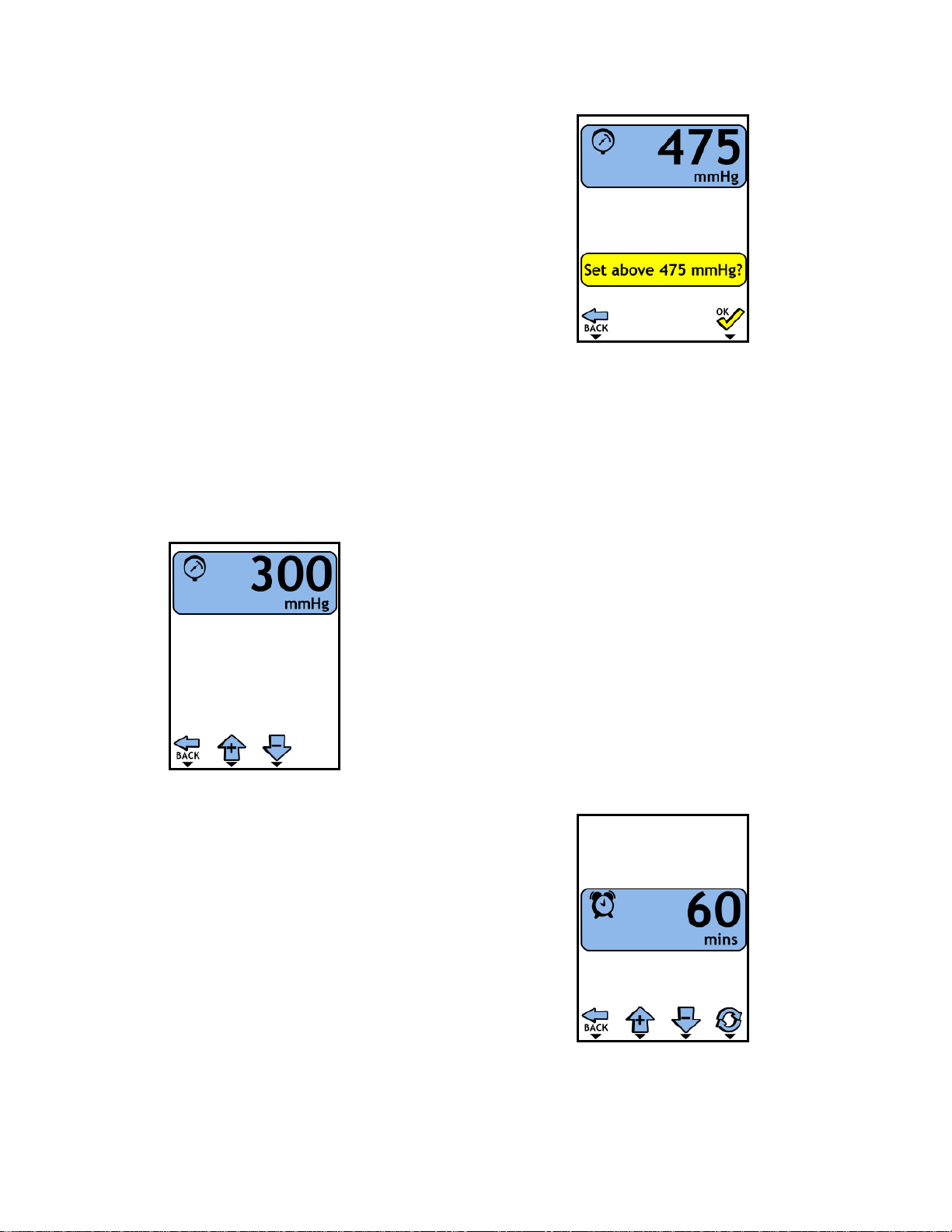
2.5PRESSURESETPOINTADJUSTMENT
a)Atthemainscreen(Figure2.5),momentarilypress
thepressureadjustmentbutton.ThePTSiiwill
displaythepressureadjustmentscreen(Figure
2.6).Apressuregaugeiconisdisplayedandthe
pressuresetpointishighlightedtoindicatethat
thesetpointisbeingadjusted.
b)Usetheincrementanddecrementbuttonsto
modifythepressureset‐pointvalue.
Momentarilypressingtheincrementbuttonwill
increasethesetpointby5mmHg.Whenthe
buttonisheldthesetpointwillincreaseby10
mmHgeverysecond.Momentarilypressingthe
decrementbuttonwilldecreasethesetpointby5
mmHg.Whenthebuttonisheldthesetpointwill
decreaseby10mmHgeverysecond.
c)Pressthebackbuttontoreturntothemainscreen.
ThePTSiiwillautomaticallyreturntothemain
screenafter3secondsifnobuttonsarepressed.
Figure2.6
PressureSetPointAdjustment
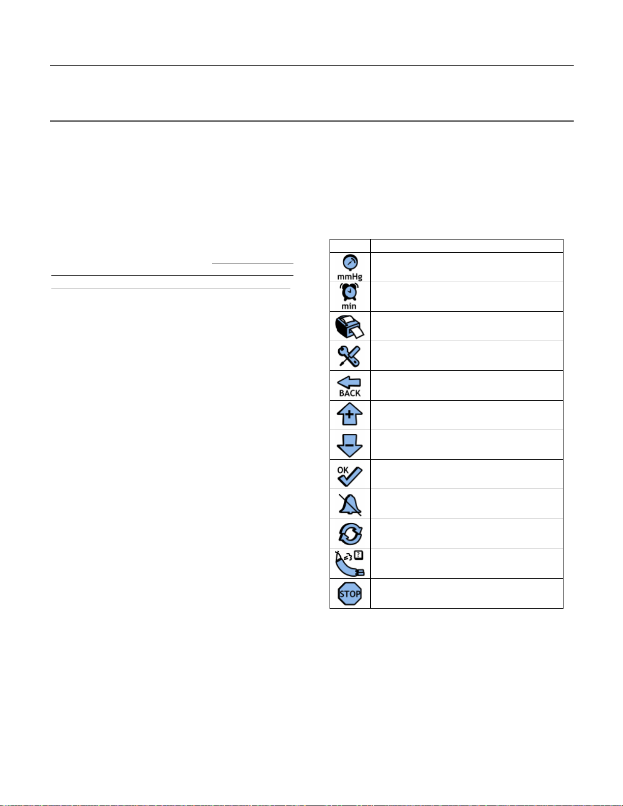
d)Notetoincreasethepressuresetpointabove
475mmHgconfirmationisrequired(Figure2.7).
MomentarilypresstheOKbuttontoenter
extendedpressuremodeorthepressbackbutton
toreturnwithoutenteringextendedpressure
mode.Ifconfirmedpressuresabove475mmHg
maybeselected.Thepressureset‐pointvalueand
cuffpressureareshownwithayellowbackground
whenapressuresetpointgreaterthan475mmHg
hasbeenselected.
Figure2.7
ExtendedPressureMode
2.6TIMELIMITSETPOINTADJUSTMENT
a)Atthemainscreen(Figure2.5)momentarilypress
thetimelimitadjustmentbutton.ThePTSiiwill
displaythetimeadjustmentscreen(Figure2.8).An
alarmclockiconisdisplayedandthetimelimitset
pointishighlightedtoindicatethetimelimitset‐
pointinbeingadjusted
b)Usetheincrementanddecrementbuttonsto
modifythepressureset‐pointvalue.Momentarily
pressingthebuttonlabeledwiththeuparrowwill
increasethesetpointby5min.Whenthebutton
isheldthesetpointwillincreaseby10minevery
second.Momentarilypressingthebuttonlabeled
withthedownarrowwilldecreasethesetpointby
5min.Whenthebuttonisheldthesetpointwill
decreaseby10mineverysecond.
c)PresstheBACKbuttontoreturnbacktothemain
screenorwaituntilthePTSiiautomaticallyreturns
tothemainscreen.
Figure2.8
TimeLimitSetPointAdjustment
13
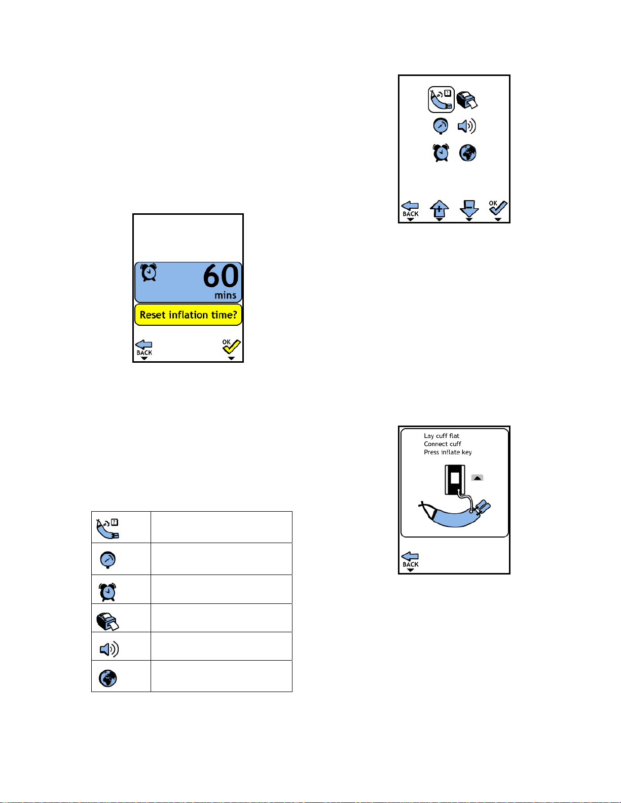
2.7.TOURNIQUETTIMERESET
Theelapsedtourniquettimemayberesettozeroat
anytimeafterthecuffhasbeeninflated.
a)Atthetimelimitsetpointadjustmentscreen
(Figure2.7)momentarilypresstheTIMERESET
button.Theresetconfirmationscreenwillbe
shown(Figure2.9).PresstheOKbuttontoreset
thetimeortheBACKbuttontoexitwithout
resettingthetime.
Figure2.9
TimeResetConfirmation
2.8SETUP/SPECIALFEATURES
Thesetup/andspecialfeaturesmenu(Figure2.10)can
onlybeaccessedwhenthecuffisdeflated.
a)Atthemainscreen(Figure2.5)momentarilypress
theSettingsbuttontoselectthesetupandspecial
featuresmenu.Usetheincrementanddecrement
buttonstomovethehighlightingboxupanddown
toselectfromthefollowing:
.
Initiateatestforleakagefrom
thecuff,hose,andconnectors
Setthedefaultpressureset
point
Setthedefaulttimelimit
Selecttheprinterlabelsize
Adjusttheaudioalarmvolume
Selectthesystemlanguagefor
messagesandprintedtext
Figure2.10
SystemSettingsandSpecialFeatures
2.9LEAKTEST
ThePTSiitourniquetsystemincludesanautomatictest
tocheckforleakagefromanattachedcuff,hoseand
connectors.
a)Atthemainscreen(asshowinFigure2.5)press
thesettingsbuttontoenterthesettingsmenu(as
showninFigure2.10).
b)Toperformatestforleakagefromthecuff,hose,
andconnectors,movethehighlightingboxtothe
cufficonandpresstheOKbutton.
c)ConnectthecuffasshowninFigure2.11.
Figure2.11
LeakTestInstructions
WARNING:Donotstarttheleakagetest(pressthe
INFLATEbutton)ifthecuffisappliedto
apatient.
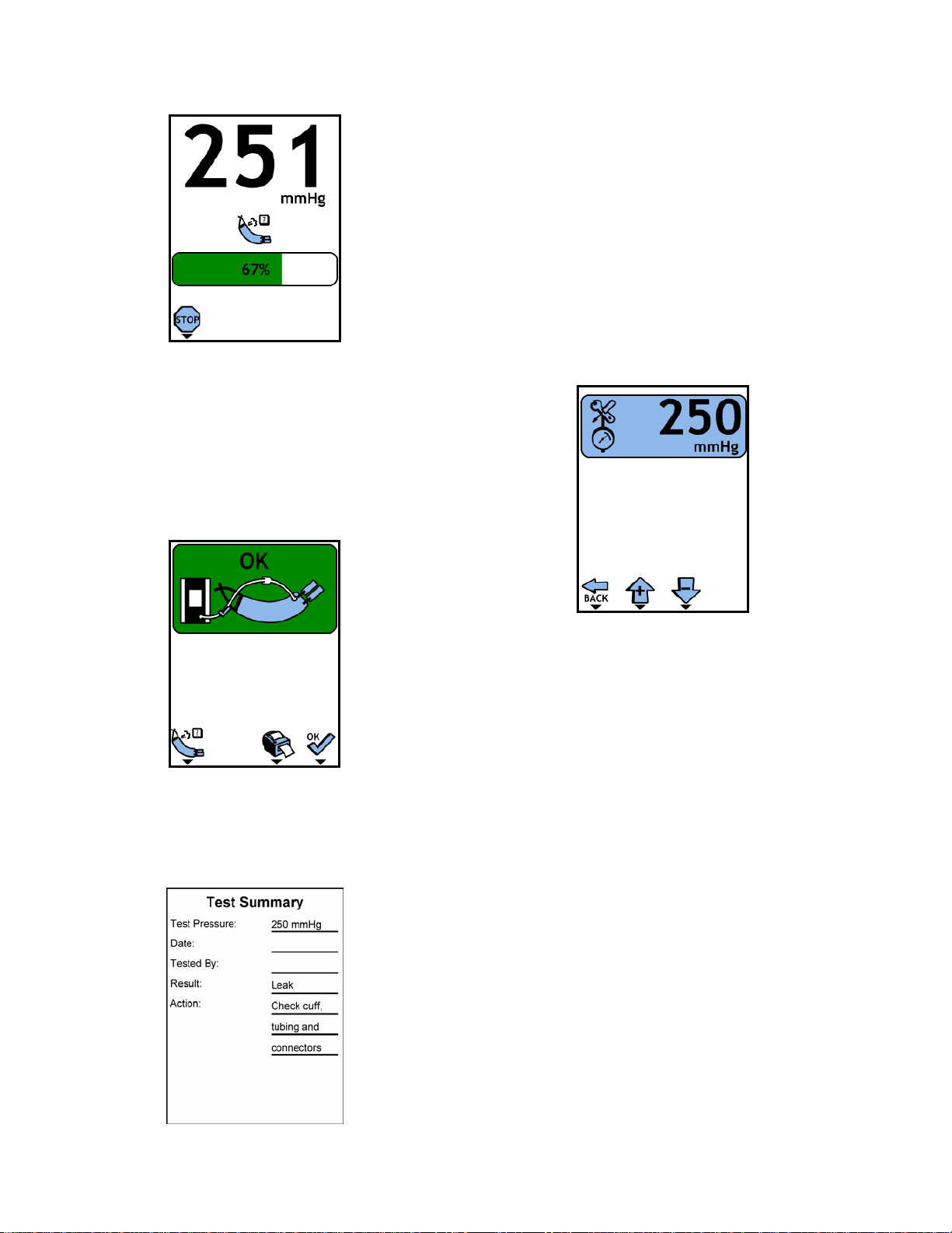
e) PresstheINFLATEbuttontostartthetestThe
testcanbestoppedatanytimebypressing
theSTOPbutton,thiswilldeflatethecuff
(Figure2.12).
14
Figure2.12
LeakInProgress
f) Thecuffwillinflatetoapproximately250
mmHganda30secondleaktestwill
commence.Attheendofthetestthecuffwill
automaticallydeflateandthetestresultwill
display(Figure2.13).PressingtheCUFFLEAK
buttonwillrepeatthetest.
Figure2.13
LeakTestComplete
g) PressingthePrintbuttonwillprintatest
summaryiftheoptionalprinterisconnected
(Figure2.14).
Figure2.14
Printedleaktestsummary
2.10SETDEFAULTPRESSURE
Thepressuresetpointwillbesettothedefault
pressurewhenthesystemispoweredon.
a)Atthemainscreen(Figure2.5)pressthesettings
buttontoenterthesettingsmenu(Figure2.10).
b)Toadjustthedefaultpressuresetpoint,movethe
highlightingboxtothepressuregaugeiconand
presstheOKbutton.
c)Usetheincrement/decrementbuttonstoadjust
thedefaultpressuresetpoint(Figure2.15).Use
theOKbuttontoacceptthenewdefaultpressure
setpoint,andreturntothesettingsmenu.
Figure2.15
DefaultPressureAdjustment
2.11SETDEFAULTTIMELIMIT
Thetimelimitsetpointwillbesettothedefaulttime
limitwhenthesystemispoweredon.
a)Atthemainscreen(asshowinFigure2.5)press
thesettingsbuttontoenterthesettingsmenu
(Figure2.10).
b)Toadjustthedefaulttimelimitsetpoint,movethe
highlightingboxtotheclockiconandpresstheOK
button.
c)Usetheincrement/decrementbuttonstoadjust
thedefaulttimelimitsetpoint(Figure2.16).Use
theOKbuttontoacceptthenewtimelimitset
point,andreturntothesettingsmenu.

15
Figure2.16
DefaultTimeLimitAdjustment
2.12PRINTERLABELSIZE
Selectthesizeofthelabelsusedforprintingevent
historiesandcuffleaktestrecords.
a)Atthemainscreen(asshowinFigure2.5)press
thesettingsbuttontoenterthesettingsmenu
(Figure2.10).
b)Toselectalabelsize,movethehighlightingboxto
theprintericonandpresstheOKbutton.
c)Usetheincrement/decrementbuttonstoselect
theprinterlabelsize(Figure2.17).PresstheBACK
buttonwhendonetoreturntothesettingsmenu.
Figure2.17
PrinterLabelSize
2.13ALARMVOLUME
Adjustthevolumeoftheaudiotonesusedtosignal
alarms.
a)Atthemainscreen(asshowinFigure2.5)press
thesettingsbuttontoenterthesettingsmenu
(Figure2.10).
b)Toadjustthealarmvolume,movethehighlighting
boxtothespeakericonandpresstheOKbutton.
c)Usetheincrement/decrementbuttonstoadjust
thealarmvolume(Figure2.18),.Presstheback
buttonwhenfinishedadjustingthevolumeto
returntothesettingsmenu.
Figure2.18
AlarmVolumeAdjustment
2.14LANGUAGE
Selectthelanguagethatwillbeusedforallalarm
messages,instructions,andprintedtext.
a)Atthemainscreen(asshowinFigure2.5)press
thesettingsbuttontoenterthesettingsmenu(as
showninFigure2.10).
b)Toadjustthesystemlanguage,movethe
highlightingboxtotheglobeiconandpresstheOK
button.
c)Usetheincrement/decrementbuttonstoselect
thesystemlanguage(Figure2.19).PresstheBACK
buttonwhendonetoreturntothesettingsmenu.
Figure2.19
LanguageSelection
2.15PRINTER
ThePTSiimaybeusedwithanoptionalindustry
standardthermallabelprinter(DelfiREF9‐2200‐150).
TheprinterissuppliedfromDelfiwithanappropriate
interfacecableforusewitheitherasinglePTSiisystem
orwithtwoPTSiisystemsinaTwinconfiguration.
16
Followtheinstructionsincludedwiththeprinterto
setupandconnecttheprintertothePTSiisystem(s).
Note:WhenusingaprinterwithtwoPTSiisystemsina
TwinconfigurationbothPTSiisystemsmustbe
poweredoninordertoprint.
DuringasurgicalprocedurethePTSiimaintainsa
recordoftourniqueteventssuchastourniquet
pressuresetting,cuffinflation,cuffdeflation,alarm
eventsandchangesinalarmlimits.Thetourniquet
eventrecordmayprintedatanytimebypressingthe
printbutton.
Pressingtheprintbuttonwiththeprinterdisconnected
orpoweredoffwillproducea“NoPrinter”alarm.If
theprinterisconnectedandunabletoprinta“Check
Printer”alarmwillbeproduced.(SeeTable2.1)
Thetourniqueteventrecordisremainsinthememory
ofthePTSiiwhenthePTSiisystemissettoStandby.
Thetourniqueteventrecordisnotclearedandnew
recordstarteduntiltheInflationbuttonispressed
whenthetourniquettimeiszero
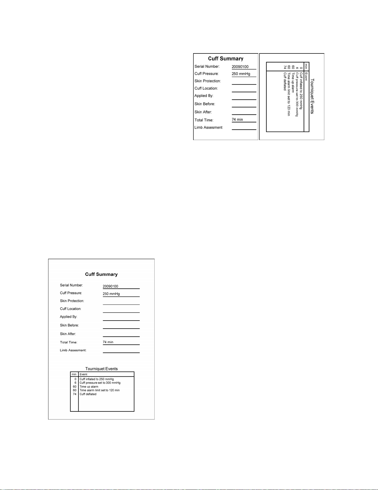
ThePTSiimaybeconfiguredtoprinttherecordona
single4”x6”adhesivebackedlabel(Figure2.20).or
ontwo2.25”x3”adhesivebackedlabels(Figure2.21).
Spaceisprovidedontheprintedlabelstorecord
relevantinformationtotheifsodesired.
Figure2.20
PrintedEventRecord(singlelabel)
Figure2.21
PrintedEventRecord(twolabels)
2.16OPERATION
NOTE:ThePTSiiunitshouldbepoweredupatleast
onceeachdayofusetoensuretheself‐testroutineis
performedregularly.ThePTSiishouldbepowered
offandleftpluggedintoACpowerwhennotinuse.
a)Pressthe‘ON/STANDBY’buttontoturntheunit
on.Theunitwillexecuteaself‐checkdiagnostic
testasdescribedinSection2.4.2ofthismanual.
Successfulcompletionoftheself‐checkindicates
thattheunitisreadyforuse.
WARNING:Ifaconnectedcuffispressurizedto50
mmHgormoreduringpower‐up,thePTSiiwill
assumethatasurgicalprocedureisinprogress,adopt
thepressuresensedinthecuffasthenewsetpoint,
andwillautomaticallyregulatethecuffatthis
pressure.Toalerttheoperatorofthiscondition,the
unitwillsoundthealarmtone,illuminatethered
alarmindicatorlight,andflashthepressuredisplay.
Theoperatorshouldimmediatelycheckthepressure
setpointandreadjusttothepropersetpointif
necessary.Thealarmwillbeclearedassoonasthe
setpointisexaminedoradjustedviathepressure
adjustmentmode.
b)Connectthehoseassemblyandasingleportcuff
totheunitatthehoseconnector.
c)Selecttheappropriatetourniquetpressureand
timelimitsetpointsforthespecificprocedure,as
specifiedbythesurgeon.Thedefaultsetpointsfor
pressureandtimelimitareretrievedfromthe
memoryduringpowerupandareactiveuntilthe
useradjuststhem(seeSections2.5and2.6).
Thesedefaultvaluescanbemodifiedbytheuser
(seeSections2.10and211).
WARNING:Inallcasesitisessentialtocheckthe
pressureandtimelimitsetpointsandconfirmthat
theyarethedesiredvaluesbeforeinflatingthecuff.

17
Foreachpatient,tourniquetpressurerequiredto
occludebloodflowtotheoperativesiteshouldbe
settotheminimumeffectivepressure.The
minimumeffectivepressuredependsonmany
factors,includingthelocationofthecuff(upperor
lowerlimb),thetypeofcuffandqualityoffitto
thelimb,whetherthelimbisnormal,
hypertrophied,orobese,thepatient's
preoperativesystolicpressure,andthemaximum
anticipatedriseinsystolicpressureduringthe
procedure.Refertothemedicalliteraturefor
currenttechniquesfordeterminingtheminimum
effectivetourniquetpressureforeachcase.
d)Preparethepatientinaccordancewithyour
establishedproceduresandcuffmanufacturer's
instructions.TheprecautionsofSection1andthe
followingareofferedasaguidetoassistinthis
process.Inmostcasesatourniquetcuffshouldbe
appliedtothewidestpartofthelimbtoallowas
muchtissueaspossibletoliebetweenthecuffand
anynervesorvascularstructuressusceptibleto
damage.Theoptimumpositionsaretheupperarm
andtheproximalthirdofthethigh.Incertain
casesoffore‐footsurgery,thetourniquetcuffcan
beappliedaroundthecalfortotheareaproximal
tothemalleoli.Foremergencysurgeryofthe
hand,asufficientlysmalltourniquetmaybe
selectedbythesurgeonforfittingaroundthe
forearm.Applyaleak‐freetourniquetcuff
smoothlywithoutwrinklesThehoseconnections
shouldbeplacedsothatthehosewillnotbe
kinkedwhenthelimbispositionedforsurgery.The
viabilityoftheskinanddeepertissuesshouldbe
establishedpriortoexsanguinationofthelimband
tourniquetinflation.Exsanguinatethelimbby
elevatingitforaminimumof2minutesand
wrappingit,distaltoproximal,usinganEsmarch,
Martin,orelasticbandage.Thebandageshould
comeupapproximatelyto1in.(2.5cm)fromthe
edgeofthetourniquetcuff.Theelasticbandageis
removedfollowinginflationofthecuff.Ifregional
anesthesiaisbeingused,theanestheticagentor
nerveblockisthenadministered.Thesurgeonwill
determine:
Whenthetourniquetistobeinflated;
Whatpressureisapplied;
Howlongthetourniquetisapplied;
Whethertoallowforintermittentaerationof
tissuebydeflatingthecuff,andthedurationof
theseaerationperiods;
Whentodeflateandremovethetourniquet.
Appropriatetourniquettimeandtheneedfor
intermittentdeflationofthecuffdependgreatly
onthepatient'sanatomy,age,andabsenceof
vasculardisease.Inmanyoperatingrooms,itis
customarytoprominentlynotethetimeof
inflation,andtowarnthesurgeonafteracertain
timehaselapsed.Thiswillallowthesurgeonto
assesstheneedforfurthertourniquettime.
e)PresstheINFLATEbuttonwhenthecuffmustbe
inflated.Theunitwillpressurizethecufftothe
pressuresetpointandstartthetourniquettime
clock.Iftheunitcannotpressurizethecuffto
within15mmHgofthesetpointinlessthan20
seconds,aleakalarmwillbesounded(seeTable
2.1forinformationaboutpossiblealarm
conditions).Thecurrentpressureinthecuffand
thetourniquettimeareshownontheLCDdisplay.
f)Whenthecuffmustbedeflated,pressandhold
theDEFLATEbutton.Afterholdingthebuttonfor
2seconds,thealarmtonewillsoundbriefly,the
pressuredisplaywillshowthefallingpressureof
thecuff,andthetourniquettimeclockwillstop
andholdthedisplayofthetourniquettime.
Removethetourniquetcuffandanyunderlying
limbprotectionmaterialimmediatelyfollowing
finalcuffdeflation.Thetimeoftourniquetcuff
removalshouldbenoted,andthecirculationof
thelimbshouldbechecked.Ifaminorleakwas
detectedduringthesurgicalprocedureaprompt
willbedisplayedstating“TESTFORLEAKS”.The
usershouldfollowthestepslistedinsection3.4to
testforleaks.
NOTE:Theelapsedtourniquettimecanbezeroed
afterthecuffisdeflatedbyfirstenteringthetime
adjustmentmodebypressingthetimelimit
adjustmentsoftkeyatthemainscreen,followedby
pressingthetimeresetsoftkey(toresettourniquet
time).Notethattheresetfeatureisonlyavailable
whenelapsedtourniquettimeisnon‐zero.
g)Afterthecuffhasbeenremoved,disconnectthe
cufffromthePTSii.Duringnormaluse,thePTSii
shouldnotbesettostandbyifpressureispresent
inthecuff.Oncethecuffhasbeenproperly
deflated,removedfromthepatientand
disconnectedfromthePTSii,theunitcanbesetto
standby.

18
2.17ALARMCONDITIONS
ThereareanumberofconditionsforwhichthePTSii
willproducevisualandaudiblealarms.Those
conditions,indicationsandappropriateactionsare
showninTable2.1.Theappropriateactionsindicated
arebasedonthemostprobablecausesandshouldonly
beusedasaguide.Othercausesofalarmconditions
mayindicateaneedforotheractions.
Thealarmindicatorlightisilluminatedandanaudible
alarmtoneisproducedwheneveraalarmconditionis
detected.
2.20.1ALARMSILENCEFUNCTION
Mostaudiblealarmtonesmaybesilencedfor30
secondsbymomentarilydepressingthealarmsilence
buttonwhichisdisplayedwheneverasilencablealarm
conditionispresent.Attheendofthesilencedperiod,
thealarmtonewillrestartifthealarmconditionhas
notbeencorrected.Thealarmtonemaybesilenced
foradditional30secondperiodsasrequired.
2.20.2PRESSUREHIGHorLOWALARMS
A"HIGHPRESSURE"or"LOWPRESSURE”alarmwill
occurwhenthepressureinacuffismorethan15
mmHgfromthepressuresetpoint.Tominimize
nuisancealarmsthatcanbecausedbyvigorous
movementofthepatient'slimbs,a1seconddelayhas
beendesignedintoalarmactuationforthese
conditions.
2.20.3.LEAKALARMS
Itispossibleforthesystemtohaveasubstantialleak
thattheunitcancompensateforbycontinual
pumping.Thistypeofleakcouldbeduetoaholein
thecufforhoseassembly,alooseorwornhose
connector,orleaksinthepneumaticcircuitinsidethe
PTSiiunit.Allleaksrequireimmediateattention,
becausetheycouldprogressintoatotalfailureofa
cufftoholdpressureatanytime.Toalerttheoperator
thatasubstantialleakispresent,the“CUFFLEAK”
alarmisactivatedwhenthistypeofleakiscontinuously
presentformorethan7seconds,eveniftheunitis
maintainingthecuffpressurewithin15mmHgofthe
setpoint.Ifa“CUFFLEAK”alarmoccurs,thecuff,hose
assembly,andhoseconnectorsshouldbecheckedfor
leaks.Ifanexternalleakcannotbefound,testthePTS
iiunitperSection3.4below.2.8.2.
2.20.4INTERNALHARDWAREFAILURES
When“SYSTEMERROR”andanumericerrorcode
appearinthepressureandtimedisplaysduringuseor
power‐up,aninternalhardwarefailurehaslikely
occurredandthePTSiiunitisunusable.Inthis
situation,itislikelythattheunithasputitselfinthe
‘safestate’mode,inwhichthepneumaticvalveand
pumparedisabledandthecurrentpressureinthecuff
isheld(intheabsenceofleaks).Itisalsolikelythata
tonewillsoundundertheseconditions.The‘safe
state’modehelpspreventunexpectedlossofocclusion
duringaprocedureifasuddenfailureoccurs.
Althoughitisveryunlikely,internalhardwarefailures
mayalsocauseerraticoperationand/orunintelligible
displayswithorwithoutalarms,andmayormaynot
putthePTSiiinthe‘safestate’mode.
Ifeithertypeoferroroccurs:
a)Settheunittostandbybypressingthe
‘ON/STANDBY’button.Thisremovespowerfrom
theinternalinstrumentcircuitryandallinstrument
functions,causingthecufftoholdpressure(inthe
absenceofleaks).
b)Ifrequired,attempttorestarttheunitbypressing
the‘ON/STANDBY’againtorestarttheunit.
c)Ifrequiredtocontinuetheprocedure,clampthe
hosewithahemostattomaintaincuffpressure,
thenimmediatelydisconnectthefaultyPTSiiunit
andconnectareplacementunit.
d)Ifcuffdeflationisrequired,disconnectthecuff
fromthePTSiiunit.
WARNING:Inallcasesofinternalhardwarefailure,
erraticoperation,orunintelligibledisplays,itis
possiblethatthepressureinthecuffisnotaccurately
displayedonthePTSiiunitandthatcuffpressure
maybepresentevenwhenthePTSiiunitappearsto
beshutdown.Theusermustimmediatelydetermine
ifthecuffisinflatedordeflatedandcontinually
monitorthecufftoensurepatientsafety.Ifdeflation
ofthecuffisnecessary,disconnectthehosefromthe
PTSiiunitorfromthecuffandconfirmthatthecuff
deflatescompletely.
19
Table2.1:AlarmsandWarnings
ConditionAppropriateaction/Remarks
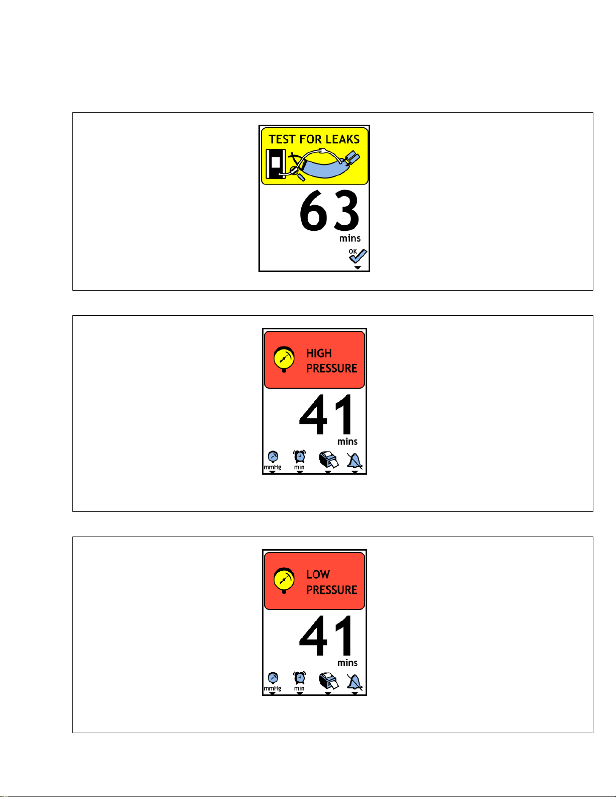
TESTFORLEAKS
Theunithasdetectedleakage
fromthecuff,hose,or
connectorsduringthetimethe
cuffwasinflated.
PresstheOKbuttontoclearthe
warningmessage
Thiswarningisonlygivenwhenthecuff
isdeflated.
Ifduringthetimethatacuffisinflated
thePTSiidetectsminorleakagefromthe
cuff,hose,orconnectorsthiswarningis
given.
Inspectthecuff,hose,andconnectorsfor
damage.Performaleaktest(see2.X).
CUFFPRESSUREHIGH
Theunithasdetectedhigh
pressureinthecuff.High
pressureisdefinedaspressure
thatis+15mmHgabovethe
pressuresetpointcontinuously
formorethan1second
Alarmmessagealternateswithcuff
pressure.
Normallycausedbytransientconditions
suchaspatientmovement,regulator
overshoot,orhoseocclusion.This
condition,foranextendedperiod,would
indicateahardwarefailureandthePTSii
unitshouldbereplaced.
Alarmwillstopautomaticallywhenever
theunitcanregulatethecufftowithin15
mmHgofthepressuresetpoint.
CUFFPRESSURELOW
Theunithasdetectedlow
pressureinthecuff.Low
pressureisdefinedaspressure
thatis+15mmHgbelowthe
pressuresetpointcontinuously
formorethan1second.
Alarmmessagealternateswithcuff
pressuredisplay
Thisconditionisgenerallycausedbya
leakinthecuff,hose,connectorsor
internalsystem.Connections,hose,and
cuffshouldbechecked.
Alarmwillstopautomaticallywhenever
theunitcanregulatethecufftowithin15
mmHgofthepressuresetpoint.
Other manuals for PTS ii
1
Table of contents
Other Delfi Medical Equipment manuals


Popular Medical Equipment manuals by other brands

Skytron
Skytron 3600B UltraSlide Operator's manual

VNS Therapy
VNS Therapy LivaNova Tunneler 402 Directions for use

NeuroMetrix
NeuroMetrix Quell 2.0 user manual

Haemonetics
Haemonetics Cell Saver 5+ Operator's manual

sensiplast
sensiplast SF-1509 Instructions for use

Aivia
Aivia A-MIP 200 Installation and user guide


