DEVI DEVIreg 535 User manual
DeviregTM 535
Installation manual
Warning!
This manual is only to be used by a
professional installer to install and
set up the thermostat properly.
It is not intended for the end-user!
INT

2
... your DEVI floor heating system
Your property has been installed with a DEVI electric floor
heating system. DEVI is Europe’s leading floor heating manu-
facturer, with over 45 years experience. We are confident that
you will be satisfied with your new system.
DEVI brings you…
An Invisible heating solution - A concealed heat source opens
up greater opportunities for decorating and furnishing.
Optimum comfort - DEVI brings you the luxury and comfort
of a warm floor as well as a pleasant room temperature.
Floor heating is the most comfortable type of heating
because it is based on the fact that warmth travels upwards;
pleasant warmth for your feet, body and head.
Low running costs – Thanks to the precise DEVI thermostat
and the placement of the heating elements right under the
floor surface the heat can be controlled optimally in order for
you to have the comfort you desire with minimal energy use.
Moreover electric floor heating is practically maintenance
free, in total keeping down the running costs.
A long lasting solution - We back-up our floor heating solu-
tions with a ten year guarantee on all our mats and cables,
and a two year warranty on our thermostats. Practically
speaking you can count on DEVI heating cables and mats
lasting as long as the house in which they are installed – and
that is without having to maintain them.
Hygiene - As DEVI produce floor heating systems, only very
gentle air is circulating, and the amount of travelling dust
particles is reduced considerably; a great relief for people
with allergies or asthma. There are also no dangerous fumes
such as carbon monoxide generated by the system.
Congratulations with…

INT
3
Table of content
Table of content
Install & configure the thermostat . . . . . . . . . . . . . . . . . . . . . .4
Placement of DeviregTM 535 ........................4
Installation of DeviregTM 535 .......................5
User’s guide to DeviregTM 535 . . . . . . . . . . . . . . . . . . . . . . . . 10
Introduction .................................... 10
Display, icons and buttons . . . . . . . . . . . . . . . . . . . . . . . 10
Increase / decrease preferred temperature. ....... 11
Using the timer function ......................... 12
Settings ......................................... 14
Setting the time .............................. 16
Setting the weekday.......................... 17
Setting the timer periods ..................... 18
Setting the comfort temperature ............. 19
Setting the savings temperature .............. 19
Setting the minimum floor temperature limit.. 19
Special features.................................. 20
Childproof mode ............................. 20
Frost protection mode........................ 20
OFF mode.................................... 21
Restore timer default settings................. 21
Switching displayed temperature ............. 22
Trouble shooting ................................ 23
Technical Specifications ............................. 24
Disposal Instruction.................................. 25
The DEVITM Guarantee ............................... 26

4
Placement of DeviregTM 535
When DeviregTM 535 is used as a room
sensor, installation height should typically be
between 80-150 cm.
At least 50 cm away from windows/doors that
will be left open occasionally.
In wet rooms it should be installed on an even
surface, according to local building regula-
tions.
Not on a wall where it will be subjected to
direct sunlight.
Not on the inner side of a wall facing the
outside.
Install & configure the thermostat
INT
5
N L
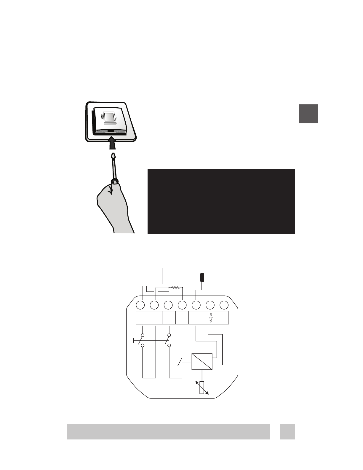
Installation of DeviregTM 535
1. To remove the front cover, gently press the release tabs
under the bottom of the thermostat with a screwdriver.
Then remove the front.
2. Connect the thermostat according to the connection
diagram
The screen of the heating cable must be connected via a
terminal strip to the earth wire of the supply cable.
Installation and connection
Max.
Load
15 A
Sensor
NO
CONNECT
Mains
180-250V~
Removing the front cover and
pushing the installation button,
is not intended to be done by
anyone else but a qualified
installer!
NL NTC
L
Load
N
Load

6
3. Choose sensor combination
When installing the Devireg™ 535 you need to choose
the type of heating and thus which sensors should be
used. You have three options:
Comfort heating: Constant temperature on the floor in
bathrooms and other rooms where a comfortable warm
surface is required.
Install the Floor sensor and choose only the Floor sensor.
Total heating: Control of room temperature in living
rooms etc. Install the Floor sensor and choose both
Floor sensor and Room sensor.
No floor sensor: A floor sensor is not present, and
cannot be installed. Choose Room sensor. (Not
recommended).
Be aware that without a floor sensor, the temperature
control can be less accurate, and overheating of the
floor is of higher risk.
DEVI recommends that a floor sensor is always
installed.
When the thermostat is used to control a floor heating
element according to EN/IEC 60335-1 and
EN/IEC 60335-2-96, always use the floor sensor
and never set the temperature limit above 35°C.
Choose sensor combination
INT
7
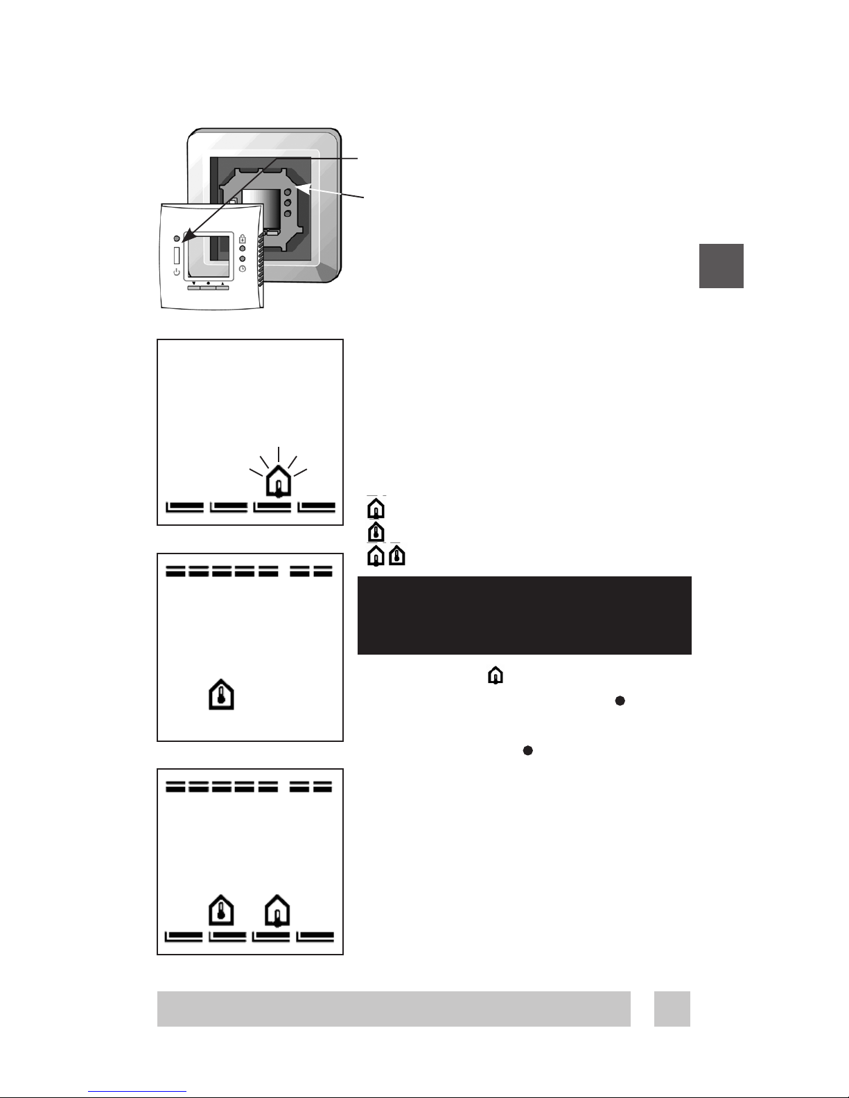
Selection of sensor type
Power on the thermostat.
With the front off, with a small screw-
driver, pencil, or needle press the
installation button.
Select the sensors to be used for the
heating system:
DeviregTM 535 is able to use two
sensors:
- a built-in room sensor
- an external sensor to be placed
in the floor.
This gives 3 options:
floor sensor.
room sensor.
both room and floor sensor.
The default is
To change this setting, press •and
use the arrow buttons ▲▼ to select
your choice. Press •to accept your
choice.
If you have selected room sensor
only, the installation procedure is
complete. Press installation button
to accept. (Go to page 9).
If you have selected floor sensor or a
combination of room- and floor sen-
sor press ▲▼ for the next setting.
Configuration - sensor
Always use floor sensor or a room
+ floor sensor combination when
used to control floor heating

8
Notice:
The floor temperature is measured where the sensor is
placed. The temperature of the bottom of a wooden floor
can be up to 10 degrees higher than the top. Floor manu-
factures often specify the max. temperature on the top
surface of the floor.
Please contact your floor supplier for maximum surface
temperature.
Maximum floor temperature.
When selecting either floor
sensor or floor and room
sensors, next screen is maximum
floor temperature.
Default setting is 35°C.
To change this setting, press •and
use the arrow buttons ▲▼ to select
your choice. Press •to accept your
choice.
If you have selected a combination of
room and floor sensor, the installa-
tion procedure is complete.
Press installation button to accept.
(Go to page 9)
If you have selected floor sensor only
press ▲▼ for the next setting.
Configuration - Max. floor temp.
When the thermostat is used to control a floor heating
element according to EN/IEC 60335-1 and
EN/IEC 60335-2-96, always use the floor sensor
and never set the temperature limit above 35°C.

INT
9
Scale
If you select DeviregTM 535 to only
use a floor sensor, mode , you
have to select the display type. The
choice is either numerical scale 1-6
or Celcius scale 5° to 45°.
Default is Celcius scale. When select-
ing Celcius, the display will show
the actual temperature at the floor
sensor.
To change this setting, press •and
use the arrow buttons ▲▼ to select
your choice.
Press •to accept your choice.
The installation procedure is now
finished.
You can use the ▲▼ for going back or
forward through the settings.
Otherwise:
Press the installation pinhole to exit
installation mode.
4. Put the frame and front back on.
Initially mains supply the thermostat for 15 hours to
fully charge the battery. The current time and day
is then kept for 80 days if mains supply is off.
All other settings are stored permanently.
Configuration - Scale
10
DeviregTM 535 is an electronic timer temperature controller,
specially designed for floor heating systems.
The DeviregTM 535, once set, automatically adjusts the
heating to meet your comfort levels, regardless of changing
weather conditions by measuring the floor temperature and
combining it with the air temperature.
Even the programming of economy temperatures (i.e. lower-
ing of temperature during the night and when you are out
of the house) is very simple. Just tell the DeviregTM 535 your
daily rhythm and choose your program.
It also features a minimum floor temp. setting, eg. for
keeping your tile floors warm in summer as well.
DeviregTM 535 Introduction
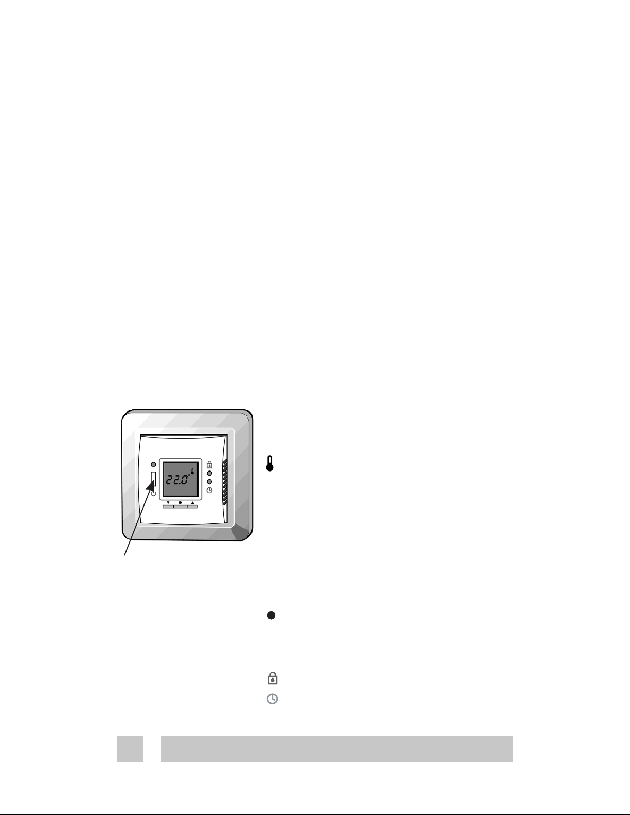
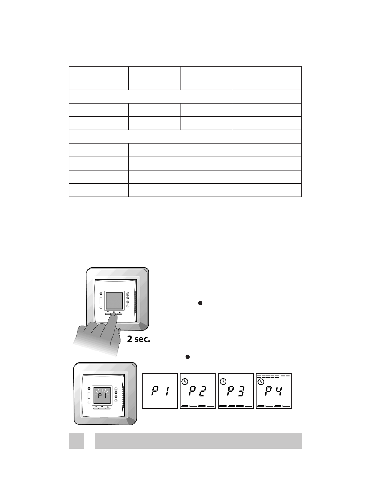
This is the standard display. The
currently measured temperature is
shown.
is shown to symbolize that current
temperature is displayed, i.e. unit
working as a thermometer.
The thermostat is operated with the
3 buttons below the display.
▼down
▲up
• select
Two pinhole buttons are available for
dedicated features
Childproof. Locks all buttons.
Settings.
Display, icons and buttons
This is a safety
switch, meaing all
electrical supply to
the thermostat is
disconnected when
turned off.
User’s guide to DeviregTM 535

INT
11
Weekdays
Settings
Room
temperature
Frost protection
Day rhythm periods
and comfort / econo-
my temperature
Childproof
Actual
temperature
is displayed
Floor
temperature
Maximum / Minimum
The display indicates:
Use the arrow buttons ▲▼ to either increase
or decrease the temperature. The tempera-
ture is changed in increments of 0.1°C.
Notice that the temperature is flashing.
Whenever something is flashing you are
making changes.
When the preferred temperature is found
you can save the setting in two ways
- Press •to accept
- Leaving it flashing for 10 seconds.
If you try to increase the set point above
the max. floor limit (p. 8) when thermostat
is operating only on floor temperature, this
icon will flash
Increase / decrease preferred temperature.
Increase / decrease temperature

12
Morning
Day
Evening
Night
Timer function
The day is divided into 4 time periods
analogous to the typical day pro-
gramming pattern:
- Morning
- Day
- Evening
- Night
These are indicated by the as
shown in the picture to the left. The
start time of each of these can be
configured.
The symbol can be:
Empty: Indicating that the
thermostat is in economy mode.
Full: Indicating that the
thermostat is in comfort mode.
The thermostat has a built-in timer function. A status bar in
the bottom of the display gives an overview of timer status.
Using the timer function
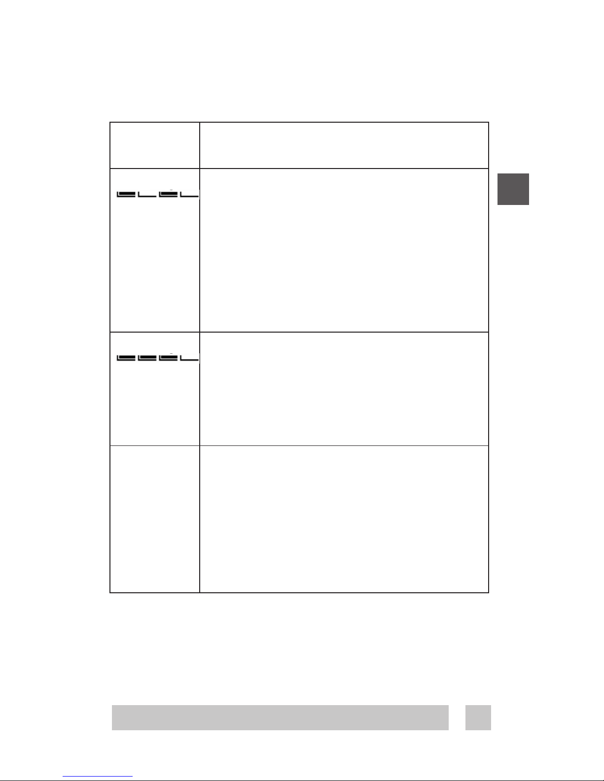
Program 1 Manual mode. The temperature is main-
tained constantly 24 hours all week.
Program 2
The temperature is lowered to economy
temperature during the day and night
period all week.
P2 is a day program for e.g. working days
where the temperature is decreased during
the middle of the day and at night. In the
morning and evening comfort temperature
is preferred.
Program 3
The temperature is lowered to economy
temperature during the night period all
week.
P3 is a program for days at home where
comfort temperature is preferred during the
day and a savings temperature at night.
Program 4 A week program where:
Mon – Fri: Program 2 and
Sat – Sun: Program 3
P4 is a week program with Monday-Friday as
workdays and Saturday-Sunday as days off.
The top 7 bars indicate Monday through
Sunday. On week days timer program 2 is
used and in weekends timer program 3.
INT
13
4 different programs can be selected
Factory setting is Program 1. Manual mode.
The 4 programs
Program 1 Manual mode. The temperature is main-
tained constantly 24 hours all week.
Program 2
The temperature is lowered to economy
temperature during the day and night
period all week.
P2 is a day program for e.g. working days
where the temperature is decreased during
the middle of the day and at night. In the
morning and evening comfort temperature
is preferred.
Program 3
The temperature is lowered to economy
temperature during the night period all
week.
P3 is a program for days at home where
comfort temperature is preferred during the
day and a savings temperature at night.
Program 4 A week program where:
Mon – Fri: Program 2 and
Sat – Sun: Program 3
P4 is a week program with Monday-Friday as
workdays and Saturday-Sunday as days off.
The top 7 bars indicate Monday through
Sunday. On week days timer program 2 is
used and in weekends timer program 3.
14
Factory settings
Floor
sensor only
Room
sensor only
Floor and
Room sensor
Temperature:
Comfort 25°C 21°C 21°C
Economy 5°C 17°C 17°C
Periods – Day rhythm:
Morning 06:00-08:00
Day 08:00-16:00
Evening 16:00-22:30
Night 22:30-06:00
The factory setting of the timer is:
You can use the above as it is, or you can change the settings
to match your day pattern. See the chapter Settings – setting
the timer periods, page 18.
To change the program:
(Remember, you need to set the
time in advance, p.17)
Keep the •button pressed for 2
seconds.
The actual program starts to flash.
It is now possible to change the
program by using the buttons ▲▼
Press •to accept
Changing timer program
INT
15
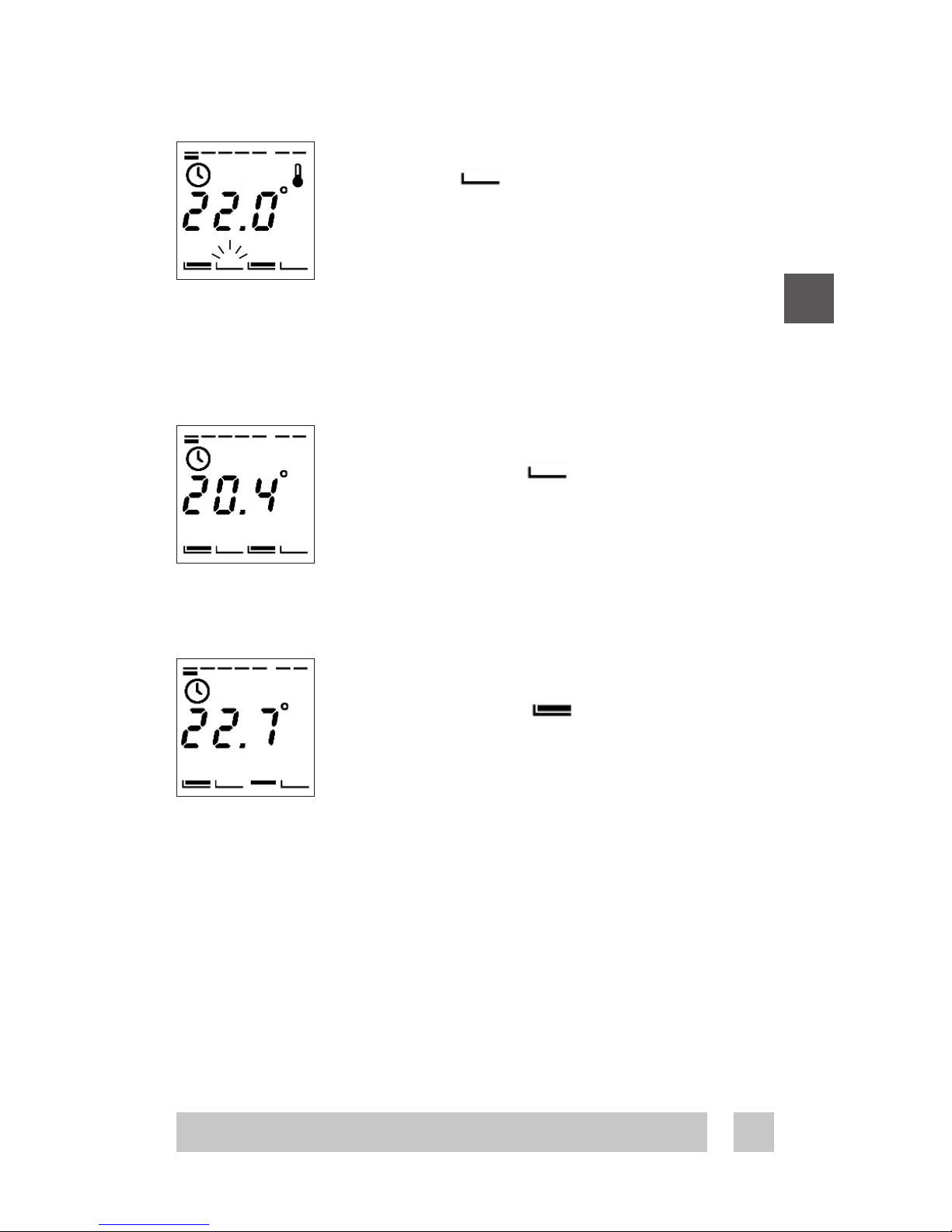
During the timer programs, P2, P3, and P4,
the flashing indicates the actual time
period.
In program 4 the actual day is also shown.
Using the arrow buttons ▲▼ in timer mode,
is somewhat different from manual mode.
If you increase/decrease the temperature
in a savings period this change only
applies to this current period, not any future
savings periods. You might use this if you
are eg. working at home in timer program 4.
If you increase/decrease the tempera-ture
in a comfort period this change applies
to all future comfort periods, until changed
again. From the perspective that you are
fine tuning the comfort temperature.
Changing timer program

16
Settings overview
Settings
All settings are under the settings menu. Here you set the
following:
- Time
- Weekday
- Timer periods configuration
(Morning, day, evening and night)
- Comfort temperature
- Savings temperature
- Min. floor temperature limit
(Only when combination of room
and floor sensor is installed).

INT
17
You enter the settings by pressing
the pinhole with a small screw
driver, pencil, or needle, the display
now changes from temperature to
time display.
By using the arrow buttons ▲▼ you
move one way or the other in the
menu.
Setting the time
By pressing the •the hours start flash-
ing, indicating you can change them
with the arrow buttons ▲▼
Press the •again to change the
minutes.
Battery Backup: The current time and
day is kept for 80 days if mains supply
is off. All other settings are stored
permanently. Initially mains supply
the thermostat for 15 hours to fully
charge the battery.
Setting the weekday
By pressing the •the weekday starts
flashing, indicating you can change it
with the arrow buttons ▲▼ Press the •
to accept
Changing the settings

18
Setting the timer periods
When programming the starting times of the 4
periods keep in mind that the thermostat will
start heating/stop heating at the given time.
Therefore some periods should start and end
before, to compensate for the time it takes to
heat up or down.
The first period bar flashes indi-cating this
is the morning period.
By pressing the •the start time of the period
starts flashing. You change it with the arrow
buttons ▲▼ in increments of 15 minutes.
Press the •to accept
The second period bar flashes indicating
this is the day period.
Setting it in the same way.
The third period bar flashes indicating this
is the evening period.
Setting it in the same way.
The fourth period bar flashes indicating
this is the night period.
Setting it in the same way.
Changing the settings
Note! When setting the time periods you cannot step back-
ward to the previous time period, until the last one is set. This
is to ensure that the periods do not overlap.

INT
19
Setting the comfort
temperature
By pressing the •the preset comfort tempera-
ture starts flashing.
You change it with the arrow
buttons ▲▼
Press the •to accept
Setting the savings
temperature
By pressing the •the preset savings temperature
starts flashing. You change it with the arrow
buttons ▲▼
Press the •to accept
It can also be set to OFF.
Setting the minimum floor
temperature limit
If the thermostat is installed as a combination
of room and floor sensor the minimum comfort
temperature on the floor can be selected.
Setting this will overrule any other set point as
you always want e.g. 20°C at the floor sensor
--.-° means that the function is disabled.
By pressing the •the preset minimum floor limit
temperature starts flashing.
You change it with the arrow ▲▼
Press the •to accept
Changing the settings

20
Special features
Childproof mode
You disable all buttons in child proof
mode by pressing the pinhole button
below with a small screw driver,
pencil, or needle.
A lock now appears in the display and
all other buttons are locked now.
To unlock press the lock symbol again
Frost protection mode
To set the thermostat in frost protec-
tion mode, you hold down ▼until you
reach the lowest setting. Now press
▼again to verify that you are not just
changing the comfort or economy
temperature, depending on the mode
or timer period the thermostat is in.
The frost icon now appears and 5.0°
flashes.
You accept the mode by
- Press •to accept
- Leaving it flashing for 10 seconds.
The thermostat is now in frost pro-
tected mode. Actual temperature is
shown.
You leave frost protection mode by
pressing ▲(0.5sec).
Other manuals for DEVIreg 535
6
Table of contents
Other DEVI Floor Heating System manuals


