Dotco 21D Series User manual

For additional product information visit our website at http://www.apextoolgroup.com
Parts Manual
45-8412
PL32-21D
09/17/2012
21D Series
.4 hp Pistol Grip Drills
21D - XX X - XX NL
Series
21D = .4 hp Drill
Handle Style
10 = Pistol Grip
50 = Straight Housing
Ouptut Speed
See page 2
Termination *
38 = 1/4" Jacobs Chuck (1BA)
40 = No Chuck
42 = 1/4" Jacobs Heavy Duty Chuck (7BA)
43 = 3/8" Jacobs Heavy Duty Chuck (2BA)
47 = 5/16" Jacobs Chuck (20BA)
51 = 3/8" Jacobs Chuck (41BA)
54 = 1/4" Female Hex Slip Chuck
* Note: A chuck or no chuck termination code must specified.
Option
NL = Oil-Less Blades

PL32--21D
September 14, 2001
Page 2
NOTE: “Model level ‘G’ ” or other letter identifies the vintage of the tool and is used for identification or when
ordering spare parts since parts interchangeability may be affected. This letter is usually stamped on the tool’s
nameplate in the position indicated. Do not use when ordering new tools.
21D--100G--38*
21D--101G--38
21D--102G--38
21D--103G--38
21D--104G--38
21D--105G--38
21D--106G--38
21D--107G--38
21D--500G--38*
21D--501G--38
21D--502G--38
21D--503G--38
21D--504G--38
21D--505G--38
21D--506G--38
21D--507G--38
25,000
5,200
3,800
3,200
2,400
1,000
700
500
Tool Termination Number
[ 38* ]
[40]
[42]
[43]
[47]
[51]
[54]
-- standard with 1/4” chuck (1BA)
-- no chuck
-- Hvy Dty 1/4” chuck (7BA)
-- Hvy Dty 3/8” chuck (2BA)
-- 5/16” chuck (20BA)
-- 3/8” chuck (41BA)
-- 1/4” Hex
( * ) Indicates the standard duty 1/4” chuck
will be shipped unless otherwise specified.
Catalog
Numbers RPM
24,000
4,750
3,500
2,800
2,100
900
650
500
RPM
PISTOL GRIP STRAIGHT HOUSING
Catalog
Numbers
GEARING REASSEMBLY
Planetary Gearing
Place a small amount of grease in each planet gear, as illustrated
at right, and place on a smooth clean surface. Insert a planet pin
— notched end up — in each gear. Then, install the correct
number of rollers ( 12 ) around each gear. Grease will hold the
rollers in position when the planet gears are removed.
PLANET
GEAR
GREASE
PLANET PIN
Figure 1
FLAT SURFACE
Timing of the Step Reduction Gear Assembly
Assemble the planet gears into the planet cage, making sure the
notched planet pins fit over the planet cage washer. Rotate each
gear until the aligning hole — on the wnd of one gear — is
diametrically opposite the “X” mark of the other gear. Hold the
gears in this position and slip the planet cage into the internal
gear. This is important to avoid “wiping out” the gear teeth.
This is the only position where the gear teeth are lined up.
Figure 2
X
X
DRILL POINT STAMPED “X”
Models:
21D--104
21D--504

PL32--21D
September 14, 2001
Page 3
MOTOR REASSEMBLY
1. Install ball bearings into both the front and rear plates.
2. Assemble rotor to rear plate/bearing assembly with the rotor’s retaining nut. Position and set the rotor as close as
possible to the rear plate, without dragging or rubbing.
a. A good practice is to stone the blade slots and polish the ends with a medium grit emery cloth.
b. Assemble components making sure the bearing is firmly seated in the rear plate.
a. One method, shown at right, is to use a piece of
pipe which is slightly longer than the rotor, and
tap lightly against work bench several times.
This helps seat threaded components.
Figure 3
HARDWOOD
BLOCK
FLAT SURFACE
PIPE OR
SPACER
ROTOR
0.001”
CLEARANCE
3. Begin tightening rotor nut without over--tightening to
avoid damaging the ball bearing. Alternately spin the
rotor while tightening until clearance is judged to be
proper—about 0.001” clearance.
b. A second method is to hold the rotor/rear plate
assembly vertically (plate downward) and strike
the edge of the plate with a wood block.
Recommended Spare Parts List for
BUCKEYE Series 21D Drills
These parts are suggested as a recommended inventory of spare parts. Where parts are small, low cost, or
easily lost, then we suggest stocking 3 to 4 for every 10 tools. Other larger, lower wear or more expensive
parts should be maintained as one (or one set) for every six to ten tools.
Part
No. Description
Qty
Per
Tool
Recommended
Spare Parts For
These Numbers
of Tools
T
o
o
l
1--5 6--10
Common Parts For All Models
1005062
Ball Bearing --
Sgl Stage & CODE “0”
Double Stage
1
2
1
2
2
4
1007537 Ball Bearing 1 1 2
1008854 Ball Bearing 1 1 2
1008914 Rotor Blade 4 8 20
1008916 Front Plate 1 1 2
1008920
Planet Pin
Single Stage
Double Stage
2
4
2
4
4
8
1008924
Planet Roller
Single Stage
Double Stage
24
48
25
50
50
100
1008977 Planet Pin -- CODE 4 2 2 4
1009879 Ball Bearing 1 1 2
1012215 Rotor Nut 1 2 4
1017579 Cylinder 1 0 1
1017780 Rear Plate 1 1 2
1110185 Spindle Nut 1 1 2
Part
No. Description
Qty
Per
Tool
Recommended
Spare Parts For
These Numbers
of Tools
T
o
o
l
1--5 6--10
Specific Parts For 21D--100 Series
1006577 Air Screen 12--3 3--4
1010250 Muffler Felt 1 1 2
1011732 O--Ring 12--3 3--4
1024712 Throttle Valve Assem.
(complete) 1 1 2
Specific Parts For Throttle Assembly (21D--100 Ser.)
1005045 Spring 1 1 2
1005081 Steel Balls 2 4 8
1008810 Retaining Ring 12--3 3--4
1021296 Valve Assembly 1 1 2
Specific Parts For 21D--500 Series
1001234 Spring 1 1 2
1008695 O--Ring 12--3 3--4
1009245 Retaining Ring 12--3 3--4
1012964 Air Screen 12--3 3--4
1019558 Muffler Felt 1 1 2

PL32--21D
September 14, 2001
Page 4
( ) Indicates recommended spare part. Order one (1)
or one set for every five (5) tools, or two sets for 6--10
tools. Small, easily lost or low cost parts should also
be ordered on the basis of 3--4 per 10 tools.
See also chart on Page 4.
•
BUCKEYE
21D Motor Housing Assemblies
21D--100 Series
PISTOL GRIP
21D--500 Series
STRAIGHT HOUSING
Assemble #1006571
Hose Adapter to motor
housing with 20--25
Ft--lbs. torque.
1006571
Hose Adapter
•1006577
Air Screen
•1024712
Package Valve Assembly
(See page 9)
1021287 Motor Housing
•1011732 O--Ring
•1010250 Muffler Felt
1013233 Baffle Ring
1019140
Motor Housing
1025255 Adapter
•1019558
Muffler Felt
1019437 Push Rod
1019436 Lever
1008340 Suspension Bail
1014174
Rocking Valve •1008695
O--Ring
1017775
Valve Seat
1019190
Hose Adapter
(1/4” NPT)
•1009245 Ret. Ring
•1012964 Screen
•1001234 Spring
1009091 Pin

PL32--21D
September 14, 2001
Page 5
( ) Indicates recommended spare part. Order one (1)
or one set for every five (5) tools, or two sets for 6--10
tools. Small, easily lost or low cost parts should also
be ordered on the basis of 3--4 per 10 tools.
See also chart on Page 4
•
“OIL--LESS” ROTOR BLADES
“Oil--Less” rotor blades can be assembled
in tools at extra cost, as follows.
Part Num. Description
1019725
1025414
(4 each) blades installed by
factory in tools. Order in tool by
adding NL to end of model code.
Package of 100 (not assembled
in tools)
For
Speed
Code
Rotor
Part
Number
Number of
Teeth
(rotor)
1, 5
2, 6
3, 7
4
0
1015872
1017518
1017517
1017516
1110122
9T
7T
6T
5T
9T
(*)Motor Chart
•1012215
Rotor Nut
•1009879 Ball Bearing
•1017780 Rear Plate
•1008914 Rotor Blade
(4 required)
*ROTOR •1017579 Cylinder
(Includes #1017422 Pin)
•1008916 Front Plate
•1007537 Ball Bearing
Motor Assemblies
Motor
Assembly
Part Number
1024744
1024771
1024687
1025263
1025594
Output Planetary Gearing
SINGLE STAGE:
21D--101--xx & 21D--501--xx
21D--102--xx & 21D--502--xx
21D--103--xx & 21D--503--xx
21D--104--xx & 21D--504--xx
1008921
Bearing Adapter
CODES 3 & 4 ONLY
•1110185
Spindle Nut
1008859 Retaining Ring
•1005062
Ball Bearing
1110127 Wave Washer
•1008854 Ball Bearing
1010099
Retaining Ring
•1008924 Planet Roller
24 Required (12 per gear)
(SHOWN OVERSIZE)
•1008920 Planet Pin
(2 Required)
PLANET CAGE
1110057 -- CODE 1
1110059 -- CODE 2
1110058 -- CODE 3
1110061 -- CODE 4
PLANET CAGE WASHER
1110054 -- CODE 1
1110055 -- CODE 2
1110056 -- CODE 3
1110055 -- CODE 4
GEAR HOUSING
1110046 (39T) -- CODE 1
1110047 (43T) -- CODE 2
1110048 (46T) -- CODE 3
1110049 (37T) -- CODE 4
PLANET GEAR (2 Req’d)
1008973 (14T) -- CODE 1
1008968 (17T) -- CODE 2
1008919 (19T) -- CODE 3
1”--20 LH thread
X
X
OUTPUT GEARING:
Install Planet Pin with
notch oriented as shown.
CODE 4
ONLY
SPEED CODE 4:
Timing of the Step
Reduction Gear Assembly
(#1008978 Planet Gears)
SEE PAGE 3
1008978 Planet Gear
(2 required)
•1008977 Planet Pin
(2 required)
1110050 Thread Cover
BUCKEYE
21D--100 & 21D--500 Series Drills
HOW TO ORDER
Specify:
REPLACEMENT PARTS
1) Quantity
2) Part Number
3) Part Name
LUBRICATION
Use No. 540397 Air Motor Oil (one quart)
or, 533485 Air Motor Oil (one gallon).
Install air line lubricator and
filter in air line ahead of tool.

PL32--21D
September 14, 2001
Page 6
( ) Indicates recommended spare part. Order one (1) or one set for
every five (5) tools, or two sets for 6--10 tools. Small, easily lost or low
cost parts should also be ordered on the basis of 3--4 per 10 tools.
See also chart on Page 4
•
BUCKEYE
21D--100 & 21D--500 Series Drills
OUTPUT GEARING:
Install Planet Pin with
notch oriented as shown.
Double Stage Gearing
•1005062
Ball Bearing
•1008924 Planet Roller
24 Required (12 per gear)
(SHOWN OVERSIZE)
•1008920 Planet Pin
(2 Required)
•1007537
Ball Bearing
PLANET CAGE WASHER
1008986 -- (CODE 5)
1009680 -- (CODE 6)
1009682 -- (CODE 7)
PRIMARY PLANETARY
GEARING ASSEMBLIES
•1110185
Spindle Nut
1008859
Retaining Ring
•1005062
Ball Bearing
1110127 Wave Washer
•1008854
Ball Bearing
1010099
Retaining Ring
•1008924 Planet Roller
24 Required (12 per gear)
(SHOWN OVERSIZE)
•1008920 Planet Pin
(2 Required)
1110057 Planet Cage
1110054 Planet Cage Washer
GEAR HOUSING
1110046 (39T)
1008973 Planet Gear
(14 teeth), 2 Req’d
1”--20
LH thread
1008921
Bearing Adapter
CODE 7 only)
1110050 Thread Cover
PLANET GEAR (2 Req’d):
1008973 (14T) -- (CODE 5)
1008968 (17T) -- (CODE 6)
1008919 (19T) -- ( CODE 7)
PLANET CAGE
1008985 -- (CODE 5)
1009679 -- (CODE 6)
1009681 -- (CODE 7)
GEAR HOUSING
1019146 (39T) -- (CODE 5)
1019147 (43T) -- (CODE 6)
1019148 (46T) -- (CODE 7)
TOOL
SPEED
CODE
PRIMARY
GEAR
ASSEMBLY
(complete)
5
6
7
1025247
1025180
1025250
1025551 OUTPUT
PLANETARY
GEARING ASSEMBLY
21D--105--xx & 21D--505--xx
21D--106--xx & 21D--506--xx
21D--107--xx & 21D--507--xx

Drill Chuck Options
Terminations 38, 42, 43, 47 & 51
Termination
Number
Chuck Part
Number
Chuck
Capacity
Thread
Mount
Spindle
Wrench
Chuck Retaining
Screw (special)
#1005078
(w/1005079 Chuck Key)
#1001505
(w/1005023 Chuck Key)
0--1/4”
0--1/4”
3/8”--24
3/8”--24
#1014512
#1014512
#7095
#7095
--38*
--4 2
Drill Chuck Options, includes:
#863420
(w/Jacobs #KG Chuck Key) 0 -- 5/16” 3/8”--24 #1014512 #7095
--4 7
#1021679 Quick Change “Slip Chuck” Option
Termination 54
Termination
Number
QC Chuck
Part Number
Output
Spindle
Thread
Mount
#1021679 1/4” hex
(internal)
3/8”--24
--5 4
Chuck Retaining Screw
1004968 (5/32”) Steel Ball
101405
Chuck Body
1014057 Chuck Sleeve
1014058 Washer
1012682 Spirolox Ret. Ring
1110399
Set Screw
#10--32 x 1/8”
1015203
Brass Pad
Jacobs
Description
#1BA
(smooth sleeve)
#7BA
(fluted sleeve)
#20BA
(fluted sleeve)
1009823 Spring
#1001252
(w/1006375 Chuck Key) 0 -- 3/8” 3/8”--24 #1014512 #1110366
--5 1 #41BA
(smooth sleeve)
#1025595 Nose Assembly
•1005062
Ball Bearing
1110050
Thread Cover
(not included in Nose Assembly)
•1110185 Spindle Nut
1008859
Retaining Ring
1110127 Wave Washer
•1008854 Ball Bearing
1”--20
L.H.
Thread
1110119 Gear Housing
1110123 Spindle
(3/8”--24 Thread)
Speed Code “0” (21D--100--xx: 25,000 rpm)
(21D--500--xx: 24,000 rpm)
BUCKEYE
21D--100 & 21D--500 Series Drills
#1004422
(w/Jacobs #K2 Chuck Key) 0 -- 3/8” 3/8”--24 #1014512 #7095
--4 3 #2BA
(fluted sleeve)
( * ) Indicates the standard chuck, which will
be shipped unless otherwise ordered with
a different “termination” number.
PL32--21D
September 14, 2001
Page 7

Package Valve Assembly
Part Number •1024712
1008248
Trigger
1008913 Push Rod
1017585 Nut
•1005081 (3/32” Dia.) Steel Ball
(2 required)
1017586 Bushing
1008695 O--Ring
•1021296
Valve Assembly
•1005045 Spring
1008811 Spring Seat
•1008810
Retaining Ring
1008261 O--Ring
1018757 O--Ring
1021241 Throttle Valve
1021306
Idling Valve
1008912 Ret. Clip
BUCKEYE
21D--100 Series Drills
PL32--21D
September 14, 2001
Page 8
Valve Disassembly
1. Remove Valve Assembly from tool housing by loosen-
ing Nut (part #1017585).
2. Remove small snap ring from rear end of assembly;
spring seat and spring will drop out.
3. Push in on trigger to force out the Valve Assembly (part
#1021296). Push Rod will now fall free.
4. Remove the two steel balls from the bushing by press-
ing against balls from the inner face of the bushing.
Parts Inspection
1. Check Valve Assembly (part #1021296) for wear. If
worn, replacement of this entire unit is recommended.
2. Check push rod for wear. Rod should have a firm, slid-
ing fit, free from excessive looseness.
Valve Reassembly
1. Insert the two balls in the holes in the bushing. Hold in
place with a small amount of grease. Then, hold bushing
horizontally to keep balls from falling out.
2. Insert push rod into the bushing with small end toward
the back (larger end) of the bushing. Slide in far enough
to allow the balls to drop below the I.D. of the bushing.
3. Slip trigger over the bushing. Push trigger in; then, us-
ing a small pointed object, force push rod forward which
allows the two balls to ride up into the undercut area in-
side the trigger -- thus, locking the trigger in place.
4. Drop #1021296 Valve Assembly into the bushing, small
end of valve first.
5. Replace spring and spring seat with ridge of seat cover-
ing end of spring. Replace snap ring.
(•) Indicates recommended spare part. Order one (1) or one set for every five (5) tools, or two sets for 6--10 tools. Small,
easily lost or low cost parts should also be ordered on the basis of 3--4 per 10 tools.
See also chart on Page 4.

BUCKEYE
21D-100 & 21D-500 Series Pistol Grip Drills PL32-21D
September 14, 2001
ALWAYS COMPLY WITH:
1. General industry Safety & Health Regulations, Part 1910,
OSHA 2206, available from: Sup’t of Documents; Government
Printing Office; Washington, DC 20402.
2. Safety Code of Portable Air Tools, ANSI B186.1 available from:
American National Standards Institute, Inc.; 1430 Broadway;
New York, NY 10018.
3. State and Local regulations.
Portions of the above codes and regulations are listed below for
quick reference.
THE FOLLOWING EXCERPTS ARE NOT INTENDED TO BE ALL
INCLUSIVE: STUDY AND COMPLY WITH ALL REGULATIONS!
1. TOOL INTENT: Tools shall be used only for purposes intended
in their design (refer to product catalog).
2. AIR SUPPLY: Test and operate tools at 90 PSIG maximum
unless tool is marked otherwise. Use recommended airline
filters-regulators-lubricators.
3. UNUSUAL SOUND or VIBRATION: If tool vibrates or produces
an unusual sound, repair immediately for correction.
4. OPERATOR PROTECTIVE EQUIPMENT: Wear goggles or
face shield at all times tool is in operation. Other protective
clothing shall be worn, if necessary. SEE REGULATIONS.
5. SAFETY MAINTENANCE PROGRAM: Employ a safety
program to provide inspection and maintenance of all phases
of tool operation and air supply equipment in accordance with
“Safety Code for Portable Air Tools.”
Safety First!
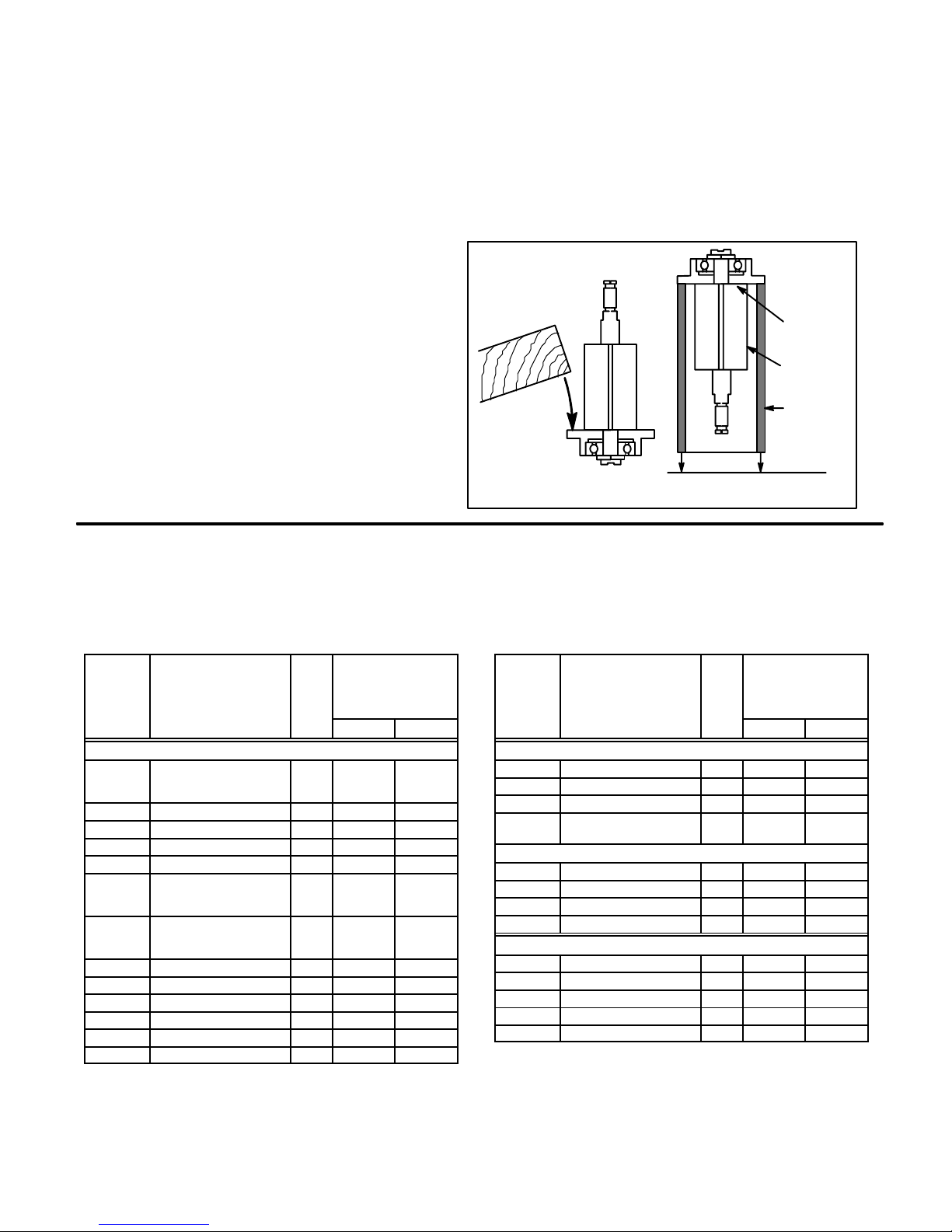
The SPEED TOLERANCE is rated speed minus 10%.The tool must NOT have a free speed higher than the
RPM stamped on the housing. Use an accurate tachometer to check the tool speed, with 90 psig air pressure at
the tool with the tool running.
CAUTION: Disconnect the air supply hose before servicing the tool.
INSTALLATION:
For best performance, a working air pressure of 90 pounds per
square inch is recommended. Pipings, fittings, and hose should be
adequate to maintain 90 psig while the tool in in operation. An air
line filter and lubricator, such as CooperTools’#F02-M Filter (1/4”
NPT) and #L02-EP Lubricator (1/4”NPT) should be used (refer to
product catalog). Hose should be blown out before attaching to tool.
LUBRICATION:
The gears in angle head style tools must be lubricated every 8
hours of operation with high quality gear grease. CooperTools’
grease #45-0980 is recommended. A Grease Gun, #45-1982, is
furnished with each geared tool. Insert the nozzle into the flush type
lube fitting, located on the side or top of the angle head, and pump
four or five times. The motor must be lubricated and moisture free.
Use a high grade SAE #5 spindle oil, such as CooperTools’
Lubricating oil #45-0918 (one quart). Two or three drops per minute
should be sufficient lubrication. NOTE: Turbine motor type tools
(10-90 & 10-95) must NOT be oiled.
LOSS OF POWER:
It is seldom necessary to disassemble this tool for loss of power. A
loss of power may not be related to the tool. First, check the air line
regulator. Also, check the air line pressure; it should be 90 psig at or
near the tool while the tool is running. Check the size of hose and
fittings to be certain they are not causing air restrictions. Make
certain they are not plugged with dirt, rust, or scale.
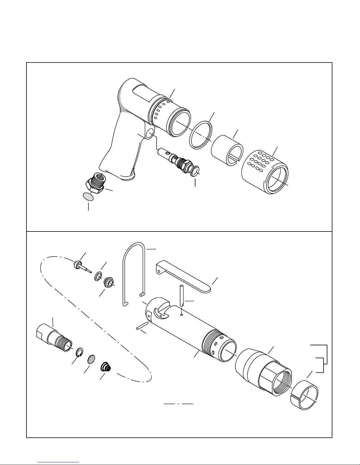
SERVICE INSTRUCTIONS:
The parts of this tool are small and require careful handling. We
recommend the tool be returned to the factory for repair. However, if
the tool is to be repaird in the field, carefully follow instructions. Do
not squeeze the tool or parts in a vise except as specified. Care
must be used during assembly and disassembly. When pressing
bearings onto a shaft, press only on the inner race. When pressing
bearings into a bore, press on the outer race only. NOTE: Ball
bearings are the shielded type. They are lubricated for life by the
bearing manufacturer and should not be washed out with solvents to
clean.
WARNING!
CHECK SPEED OF TOOL WITHOUT WHEEL BEFORE IT IS RELEASED FOR USE.


45-8412 (PL32-21D)/Printed in USA 11/2012/Copyright © Apex Tool Group, LLC
Apex Tool Group, LLC
1000 Lufkin Road
Apex, NC 27539
Phone: 919-387-0099
Fax: 919-387-2614
www.apextoolgroup.com
Sales & Service Centers
Note: All locations may not service all products. Please contact the nearest Sales & Service Center for
the appropriate facility to handle your service requirements.
Detroit, MI Houston, TX Lexington, SC Los Angeles, CA
Apex Tool Group Apex Tool Group Apex Tool Group Apex Tool Group
Sales & Service Center Sales & Service Center 670 Industrial Drive Sales & Service Center
2630 Superior Court 6550 West Sam Houston Lexington, SC 29072 6881 Stanton Avenue
Auburn Hills, MI 48326 Parkway North, Suite 200 Tel: 800-845-5629 Unit B
Tel: 248-393-5640 Houston, TX 77041 Tel: 803-951-7544 Buena Park, CA 90621
Fax: 248-391-6295 Tel: 713-849-2364 Fax: 803-358-7681 Tel: 562-623-4457
Fax: 713-849-2047 Fax: 562-802-1718
Seattle, WA York, PA Canada Germany
Apex Tool Group Apex Tool Group Apex Tool Group Apex Tool Group
Sales & Service Center Sales & Service Center Sales & Service Center GmbH & Co. OHG
2865 152nd Avenue N.E. 3990 East Market Street 5925 McLaughlin Road Industriestraße 1
Redmond, WA 98052 York, PA 17402 Mississauga, Ont. L5R 1B8 73463 Westhausen
Tel: 425-497-0476 Tel: 717-755-2933 Canada Germany
Fax: 425-497-0496 Fax: 717-757-5063 Tel: 905-501-4785 Tel: +49 (0) 73 63 81 0
Fax: 905-501-4786 Fax: +49 (0) 73 63 81 222
England France China Mexico
Apex Tool Group Apex Tool Group S.N.C. Cooper (China) Co., Ltd. Cooper Tools
GmbH & Co. OHG 25 rue Maurice Chevalier a company of de México S.A. de C.V.
C/O Spline Gauges B.P. 28 Apex Tool Group, LLC a company of
Piccadilly, Tamworth 77831 Ozoir-La-Ferrière 955 Sheng Li Road, Apex Tool Group, LLC
Staffordshire B78 2ER Cedex, France Heqing Pudong, Shanghai Vialidad El Pueblito #103
United Kingdom Tel: +33 1 64 43 22 00 China 201201 Parque Industrial Querétaro
Tel: +44 1827 8741 28 Fax: +33 1 64 43 17 17 Tel: +86-21-28994176 Querétaro, QRO 76220
Fax: +44 1827 8741 28 Fax: +86-21-51118446 Mexico
Tel: +52 (442) 211-3800
Fax: +52 (442) 103-0443
Brazil Hungary
Cooper Tools Industrial Ltda. Apex Tool Group
a company of Hungaria Kft
Apex Tool Group, LLC Platànfa u.2
Av. Liberdade, 4055 9027 Györ
Zona Industrial - Iporanga Hungary
18087-170 Sorocaba Tel: +36 96 66 1383
SP Brazil Fax: +36 96 66 1135
Tel: +55 15 2383929
Fax: +55 15 2383260
Table of contents
Popular Drill manuals by other brands

Ryobi
Ryobi P205G Operator's manual

Bosch
Bosch 1132VSR Operating/safety instructions

HIKOKI
HIKOKI DS 14DBSL Handling instructions

GÜDE
GÜDE GTB 14/509 Translation of the original instructions

Parkside
Parkside PABS 10.8 A1 - MANUAL 3 Operation and safety notes

EINHELL
EINHELL TC-ID 720/1 E Original operating instructions