dr trimmer mower Pro User manual


DR®TRIMMER/MOWER™Assembly & Operating Instructions i
And congratulations on your purchase of a new DR®
TRIMMER/MOWER™!
We have done our utmost to ensure that your DR®will
be one of the most trouble-free and satisfying pieces of
equipment you have ever owned.
Please let us know of any questions or problems you
may have. We want to answer or correct them as quickly
as possible. (When you do call or write, please have your
serial number and/or order number handy—it will speed
things up!) We also hope to hear from you on how much
you like your new helper.
And please tell your friends about your new DR®
TRIMMER/ MOWER™. Having DR®Owners spread the
word about our products and our way of doing business is
the best advertising we can have, and it's the best way to
help us provide even better service in the years to come.
Thanks once again!
for all of us at...
COUNTRY HOME PRODUCTS®

DR®TRIMMER/MOWER™Assembly & Operating Instructionsii
Safety Instructions
We want you to enjoy years of productive use from your DR®TRIMMER/MOWER™. We don't
want you to get injured, so please take a few moments to read the following guidelines for safely
operating your new machine.
Dress Appropriately
·Always wear protective goggles (provided with your DR®TRIMMER/MOWER™) while
mowing, to protect your eyes from possible thrown objects.
·Wear shoes with non-slip treads when using your DR®TRIMMER/MOWER™. If you have
safety shoes, we recommend wearing them. Do not use the machine while barefoot or
wearing open sandals.
·Wear long pants while trimming, and avoid wearing loose clothing or jewelry which might
get caught on the mower's moving parts.
·Use ear muffs or ear plugs to protect your valuable hearing.
Preparation
·Read these Assembly & Operating Instructions and the engine manufacturer's owner's
manual before you use the DR®TRIMMER/MOWER™. Become familiar with the controls,
engine and service recommendations to ensure the best performance from your machine.
·Inspect the area you'll be working in for hidden objects such as large rocks, logs, rope, wire,
garden tools, etc., and remove these obstacles before mowing. Do not attempt to mow over
obstacles as this could damage the machine and cause injury.
Operating the Machine Safely
·Only use the DR®TRIMMER/MOWER™for trimming and mowing grass, weeds, and other
growth as specified in this manual.
·Use only manufacturer-recommended replacement parts and accessories.
·Never bend, cut, fit, weld, or alter the DR®TRIMMER/MOWER™in any way.
Modifications to your machine could cause personal injuries and property damage, and may
void your warranty.
·ALWAYS shut off the engine and remove the spark plug wire prior to making any
adjustments to the machine. If you have to stop to remove grass or debris from the underside
of the deck, ALWAYS disconnect the spark plug wire first.
·The exhaust area on the engine becomes very hot. Allow the engine to cool before doing
maintenance or making adjustments.
·When operating over uneven terrain and slopes, use EXTREME CAUTION and ensure solid
and firm footing at all times.
·Use extra caution when mowing in wet, slippery conditions.
·As with any trimmer, the tips of the cutting cords on the DR®TRIMMER/MOWER™can
throw sticks, small stones, gravel, and bits of debris for long distances at great velocity. The
faster the cutting cords are spinning, the farther debris may be thrown. Do not move over
loose materials such as gravel or mulch with the trimmer head spinning. Doing so could
cause personal injury or property damage from thrown objects.

DR®TRIMMER/MOWER™Assembly & Operating Instructions iii
·Turn off the engine whenever you leave the operating position. Never leave the engine
running when refueling, changing cords or checking, cleaning or working on the machine.
·Never allow children or animals near the work area. Keep at least 50 feet clear of
bystanders, and always turn the machine off when someone approaches to avoid causing
injury from thrown objects.
·Never allow children or people unfamiliar with these instructions to use the DR®
TRIMMER/ MOWER™.
·Be cautious when using your DR®TRIMMER/MOWER™around fencing, wires, ropes, and
hoses. It is possible that these and other debris can become wound around the line plates of
the machine, potentially damaging the bearings or injuring the operator.
·Use the machine only in daylight or good artificial light.
·Never operate the machine with a damaged shield or without the shield in place.
·Do not operate the machine when under the influence of alcohol or medication.
·Watch for traffic when mowing near roadways.
Safety with Gas-Powered Machines
·Do not run the engine in an enclosed area or without proper ventilation.
·Store all fuel in containers specifically designed for this purpose. Plastic containers are more
likely to prevent sediment and condensation problems.
·Refuel outdoors only, and do not smoke while refueling or operating the machine.
·If gas is spilled, do not attempt to start the engine. Move the machine away from the area of
the spill and avoid creating any source of ignition until the gas vapors have dissipated. Wipe
up any spilled fuel to prevent a fire hazard, and properly dispose of the waste.
·Allow the engine to cool completely before storing in any enclosure. Never store the
machine with gas in the tank near an open flame or spark.
·Do not change the engine governor settings or modify the engine speed.
·Some state and local regulations require the use of a spark arrester on gas powered
engines. Contact your local fire marshal or forest service for specific information
pertaining to your area. If you are required to use a spark arrester, please contact one
of our Customer Service Representatives for assistance in obtaining and installing one.
Warning to All California and Other Users
Under California and Washington State laws, and the laws of some other states, you are not
permitted to operate an internal combustion engine using hydrocarbon fuels without an engine
spark arrester. All DR®TRIMMER/ MOWERS shipped to California and Washington state are
provided with spark arresters. Failure of the owner/operator to maintain this equipment in
compliance with state regulations is a misdemeanor under California law and may be in violation
of other state and/or federal regulations. Contact your local fire marshal or forest service for
specific information in your area.

DR®TRIMMER/MOWER™Assembly & Operating Instructionsiv
Table of Contents
SAFETY INSTRUCTIONS..............................................................................................................................................II
Dress Appropriately........................................................................................................................................................ ii
Preparation...................................................................................................................................................................... ii
Operating the Machine Safely......................................................................................................................................... ii
Safety with Gas-Powered Machines .............................................................................................................................. iii
Warning to All California and Other Users ................................................................................................................... iii
TRIMMER PARTS & COMPONENTS ..........................................................................................................................1
ASSEMBLY COMPONENTS...........................................................................................................................................2
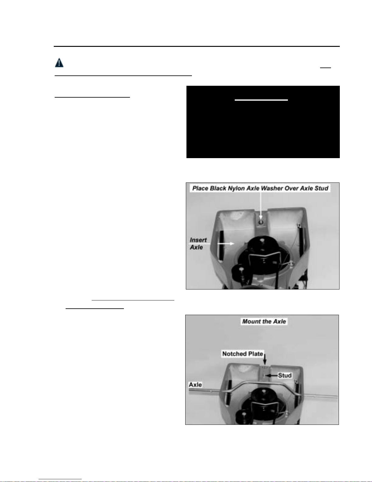
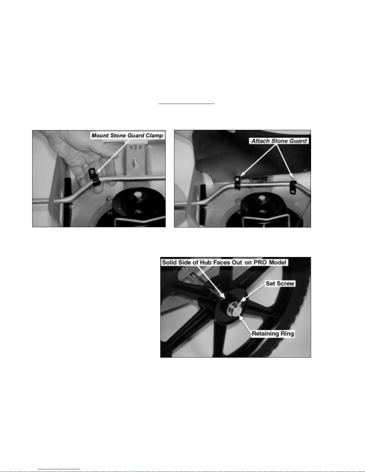
ASSEMBLY ........................................................................................................................................................................3
CONTROLS & FEATURES .............................................................................................................................................9
STARTING & OPERATING..........................................................................................................................................10
Electric-Starting.............................................................................................................................................................10
Manual-Starting .............................................................................................................................................................10
Stopping the Engine.......................................................................................................................................................11
Engaging the Trimmer Head..........................................................................................................................................11
Stopping the Cords Spinning .........................................................................................................................................11
Using the Parallel Trimming Action (PTA™) Feature ...................................................................................................12
Cutting Cords.................................................................................................................................................................13
Cord Tips.......................................................................................................................................................................15
Adjusting the Cutting Height.........................................................................................................................................16
Mow-Ball™Support.......................................................................................................................................................16
Adjusting the Handlebar ................................................................................................................................................16
Obstacles........................................................................................................................................................................17
Heavy Growth................................................................................................................................................................18
Wet Conditions ..............................................................................................................................................................18
Very Dry Conditions......................................................................................................................................................18
Slopes.............................................................................................................................................................................18
Windrows.......................................................................................................................................................................19
Firebreaks.......................................................................................................................................................................19
End-of-Season Garden Clean-Up...................................................................................................................................19
MAINTENANCE..............................................................................................................................................................20
Regular Maintenance.....................................................................................................................................................20
Battery Care (Electric-Starting Models Only) ...............................................................................................................21
To Remove the Mow-Ball™Support Assembly.............................................................................................................22
To Reassemble the Mow-Ball™Support Assembly.......................................................................................................23
To Partially Lower the Bearing Housing Assembly (to remove debris)........................................................................24
To Check the Bearing Housing Assembly for Damage.................................................................................................24
To Remove and Replace the Bearing Housing Assembly .............................................................................................25
To Replace the Belt........................................................................................................................................................27
To Adjust the Belt Tension through the Trimmer Control Cable ..................................................................................28
To Adjust the PTA™Feature..........................................................................................................................................29
TROUBLESHOOTING...................................................................................................................................................30
PARTS LIST.....................................................................................................................................................................34
SCHEMATIC DRAWINGS ............................................................................................................................................36
DAILY CHECKLIST FOR THE DR®TRIMMER/MOWER™...........................................................BACK COVER

DR®TRIMMER/MOWER™Assembly & Operating Instructions 1
Trimmer Parts & Components
The following parts and assembly components should be in your DR®TRIMMER/MOWER™
package. Please check your shipping box(es) and parts package(s) for the items listed below. If
your shipment is incomplete or if you have any questions, please call us TOLL-FREE
1(800)DR-OWNER(376-9637).
Assembly Components:
1—Upper Handlebar [#143641], Commercial Model, or
[#144071], PRO Model
1—Lower Handlebar [#143631], Commercial Model, or
[#144061], PRO Model
2—Handlebar Adjuster Assemblies [#145801] in separate plastic bag
1—Axle [#114261]
1—Rubber Stone Guard [#116801]
1—PTA™Lever [#118221]
1—Acrylic Shield Assembly [#120521]
2—Wheels [#139861], Commercial Model, or
[#121761], PRO Model
Parts Bag Contents:
2—Wheel Retainer Rings [#119551]
2—Stone Guard Clamps [#131031]
1—Black Nylon Axle Washer [#121521]
4—5/16" Washers [#121691]
5—Lock Nuts 5/16"-18 (larger size) [#110761]
2—Set Screws 1/4"-20 Square Head [#120161]
7—Slotted Hex Head Bolts 10-24 x 5/8" Long [#114781]
7—Lock Nuts 10-24 (smaller size) [#118731]
2—U-Bolts [#114851]
1—PTA™Lever Grip [#117491]
Please refer to Figure 1 on the next page when preparing to assemble your DR®TRIMMER/
MOWER™. We recommend laying the parts out in sets, as we have shown them, before
assembly.

DR®TRIMMER/MOWER™Assembly & Operating Instructions2
Assembly Components
Figure 1

DR®TRIMMER/MOWER™Assembly & Operating Instructions 3
Assembly
WARNING! Do not attempt to start the engine until all assembly steps are complete, and
you have ADDED GAS AND OIL to the engine.
Tools & Supplies Needed:
• flat head screwdriver
• 1/2" and 3/8" wrenches, adjustable
wrench, or socket set
• 7/16" wrench (Commercial Model)
• pliers
• SAE30 High Detergent motor oil
• funnel (preferably with filter)
• unleaded gasoline
Step 1: Install the Axle
1. Start with the orange housing upside
down. Leave the packaging on the
front end in place to balance the
machine during assembly.
2. Place the black nylon axle washer
over the axle stud at the center back
of the housing (Figure 2).
3. Insert the axle through the slot in the
outside of the housing so the plate
faces the axle stud (Figures 2 & 3).
4. Center the axle and slide the hole in
the notched plate over the stud so that
it rests flush against the nylon
washer. Be sure the axle is seated on
the axle stud solidly (Figure 3).
5. Screw a 5/16" lock nut onto the axle
stud using a 1/2" wrench or socket.
Tighten it until there is resistance, then
back off 1/2 turn. [If the bolt is too
tight, it will be hard to operate the
Parallel Trimming Action (PTA™)
Feature.]
Figure 2
Figure 3
WARNING!
THIS MACHINE IS SHIPPED WITHOUT OIL!
TRACES OF OIL MAY BE IN RESERVOIR
FROM FACTORY TESTING, BUT YOU MUST
ADD OIL BEFORE STARTING ENGINE. FILL
RESERVOIR SLOWLY, CHECKING DIPSTICK
FREQUENTLY TO AVOID OVERFILLING.

DR®TRIMMER/MOWER™Assembly & Operating Instructions4
Step 2: Attach the Rubber Stone Guard
1. Take one of the two stone guard clamps and position it around the axle (Figure 4). Install the
second clamp midway along the opposite side of the axle in the same way. Turn the open
ends of the clamps upward.
2. Holding the rubber stone guard vertically over the axle, slip one side of the stone guard in
between the clamp end so that the hole in the guard is aligned with the holes in the clamp.
Insert a 5/8" long bolt and attach a lock nut (Figure 5). Tighten with a 3/8" wrench or socket
and screw driver until the threads show. Do not over tighten. Repeat on the other side. The
stone guard should swing freely from the axle.
Step 3: Install the Wheels
1. Mount each wheel on the axle. Push
the wheels firmly against the axle
stop.
2. Place a retaining ring on the axle,
against the wheel, and tighten the set
screw (Figure 6) with a wrench or
pliers. Repeat on the other side.
Step 4: Set the Machine
Upright
Note: Be careful not to kink, twist or
stretch the control cables.
1. Remove the packaging from the front
end.
2. Stand at one side of the machine, holding on to one wheel with one hand, and the nose of the
machine with the other. Lift the nose of the machine up and over until the Mow-Ball™
Support is resting on the ground and the machine is upright (most of the weight is on the
wheels during this maneuver).
Figure 4 Figure 5
Figure 6

DR®TRIMMER/MOWER™Assembly & Operating Instructions 5
3. Bring the upper handlebar section up and over the front end of the machine. Let it rest there.
Caution: DO NOT add gas or oil to the engine at this time.
Step 5: Install the Handlebars
A) Lower Handlebar
Note: There are 2 U-bolts, 4 washers,
and 4 lock nuts in your parts bag that will
be needed for the lower handlebar
assembly.
1. With the control cables on the inside
of the handlebar, position the lower
handlebar over the bolt holes in the
trimmer frame (Figure 7).
2. Place the U-bolts through the bolt
holes in the trimmer frame from the
inside out (Figure 7). Be sure the
black control cable on the underside of
the trimmer is clear of the U-bolt.
3. Mount the washers and nuts and secure
them snugly on both sides (Figure 8).
B) Upper Handlebar
Note how the components of the handlebar
adjuster assemblies go together before
mounting the upper handlebars. There is
an inside and an outside adjuster. The
outside adjuster has a beveled edge
(Figure 9).
1. Take apart the handlebar adjustment
assemblies one at a time.
2. Insert the bolt through the bottom hole
in the lower handlebar from the inside
facing out (Figure 9).
3. Mount the inside adjuster (no beveled
edge) with the cup snug to the lower
handlebar.
4. Mount the spring on the bolt, then add
the outside adjuster (has a beveled
edge). There is a notch at the top of
each adjuster—they should line up,
and the teeth should fit snuggly
together
(Figure 9).
Figure 7
Figure 8
Figure 9

DR®TRIMMER/MOWER™Assembly & Operating Instructions6
5. Make sure the control cables are over the lower handlebar. Mount the upper handlebar with
the bolt going through the bottom hole. The cup in the outside adjuster should fit snuggly
against the upper handlebar (Figure 9).
6. Add the knob and tighten.
7. Repeat on the other side.
Step 6: Install the Parallel
Trimming Action (PTA™) Lever
1. Insert the straight end of the L-shaped
PTA™lever through the hole in the
center of the lower handlebar (Figure
10).
2. Align the flat end of the PTA™lever
with the corresponding hole in the
PTA™latch installed at the center rear
of the frame (Figure 11).
3. Mount a 5/8" long bolt through the two
holes. Tighten with a lock nut until
there is slight resistance, then back off
two full turns.
Note: If the lock nut is too tight, the
PTA™lever will be hard to engage.
4. Install the black, vinyl handle grip over
the operator's end of the PTA™ lever.
Step 7: Attach the Acrylic
Engine Shield
Use the four remaining sets of 5/8" long
bolts and lock nuts to attach the acrylic
engine shield.
You may find it easier to tip the machine
back on its handlebars in order to reach the
underside.
1. Position the shield on the frame in
front of the engine with the bend at the
top facing the handlebars.
2. Insert the bolts from the outside facing
in, screw on the nuts and tighten
(Figure 12).
Figure 10
Figure 11
Figure 12

DR®TRIMMER/MOWER™Assembly & Operating Instructions 7
Step 8: Connect the Battery Wires (Electric-Starting models only)
To prevent the battery from discharging during shipment, all electric-starting trimmers are
shipped with one or both battery wires disconnected.
On the PRO Model:
Connect the two black wires by pushing the plastic ends together (Figure 13). See the red wires
for comparison. The wires are located on the left front side when standing in the operator's
position.
On the Commercial Model:
Connect both wires to the battery terminals as shown in Figure 14. Red to red and black to
black.
Note: Be careful not to hit the wires on the metal bracket. You may short them out.
Step 8a: Connect the Throttle Cable (Commercial Model Only)
Tools Needed:
• 7/16" wrench
1. Remove the 1-1/2" long bolt from the
left handlebar.
2. Attach the throttle control to the left
handlebar with the 1-1/2" long bolt
(Figure 14a). The throttle cable
should go around the front of the
engine, along the left side of the
engine, then up toward the handlebar.
Be sure the cable is over the lower
handle bar before attaching it.
3. Secure the throttle cable to the lower
handle bar with a cable tie.
Figure 13 Figure 14
Figure 14a

DR®TRIMMER/MOWER™Assembly & Operating Instructions8
Step 9: Add Oil and Gas
WARNING! You must add oil before starting engine. There may be 1 to 2 ounces of
oil left in your machine from factory testing. Check the dipstick frequently while
adding oil to avoid overfilling.
Reminder: To avoid confusion, we
recommend leaving the caps on the fuel
and oil fills until you are ready to pour
either gasoline or oil into the correct fill.
1. Use SAE30 High Detergent oil. Add
approximately 15 ounces of oil and
wait one minute for the oil to settle.
Check the dipstick, then continue
adding small amounts of oil and
rechecking the dipstick until it reaches
the full mark (Figure 15). Do not
overfill.
Important! To get an accurate
reading when checking the oil level:
• On the PRO model the dipstick should be screwed down.
• On the Commercial model the dipstick should not be screwed down.
Please refer to your engine manufacturer's owner's manual for more detailed oil information.
2. Fill the gas tank to within 1/4 inch of the top with fresh, unleaded gas. See your engine
manufacturer's owner's manual for more detailed fuel recommendations.
Caution: Once you have added the oil and gas, avoid tipping the trimmer back on its
handlebars. Doing so will cause the cylinder to fill with oil. If you need to reach the underside of
the trimmer, drain the oil and gas first, or set the machine up on a workbench.
Figure 15

DR®TRIMMER/MOWER™Assembly & Operating Instructions 9
Controls & Features
Note: PRO Model Shown
Figure 16

DR®TRIMMER/MOWER™Assembly & Operating Instructions10
Starting & Operating
Electric-Starting
1. Push the throttle lever on the left side
of the handlebar (Figure 16) all the
way forward to the START position.
2. On the PRO model:
Prime the engine. Make sure you
completely cover the air hole. Push
the black primer bulb (Figure 17) for
three seconds and completely release
it, letting it pop back to its original
position. Repeat three to four times.
The Commercial model does not have
a primer.
Note: Priming is usually unnecessary
when restarting a warm engine. In
cool weather priming may need to be
repeated.
3. Turn the key (Figures 17 & 18) to the
START position until the Trimmer
starts, then release. The key will snap
back to the RUN position.
Note: The key switch on the
Commercial model is located between
the engine and the shield on the left
side of the trimmer (Figure 18).
Manual-Starting
Can be used with both Manual- and
Electric-Starting models.
1. Push the throttle lever on the left side
of the handlebar (Figure 16) all the way forward to the START position.
Figure 17
Figure 18
WARNING!
THIS MACHINE IS SHIPPED WITHOUT OIL! TRACES OF OIL MAY BE IN RESERVOIR
FROM FACTORY TESTING, BUT YOU MUST ADD OIL BEFORE STARTING ENGINE.
FILL RESERVOIR SLOWLY, CHECKING DIPSTICK FREQUENTLY TO AVOID
OVERFILLING.

DR®TRIMMER/MOWER™Assembly & Operating Instructions 11
2. On the PRO model:
Prime the engine. Push the black primer bulb (Figure 17) for three seconds and completely
release it, letting it pop back to its original position. Repeat three to four times.
The Commercial model does not have a primer.
Note: Priming is usually unnecessary when restarting a warm engine. In cool weather
priming may need to be repeated
3. Grasp the recoil starter handle (Figure 16), and slowly pull until resistance is felt. Let the
cord retract a little bit, then pull the cord rapidly to start the engine. One or two pulls usually
starts the DR®TRIMMER/MOWER™, but it may be necessary to repeat the priming (on
PRO models).
Stopping the Engine
Move the throttle lever (Figure 16) back to the STOP position.
Note that on Electric-Starting models the key does not stop the engine. You must throttle down.
The key has a pressure lock that prevents it from vibrating loose during operation. If you wish to
remove the key, push it in and then quickly and firmly pull it out. If the key is difficult to
remove, spray FLUID FILM®or a comparable lubricant into the keyhole.
Engaging the Trimmer Head
1. Bring the bail bar (Figure 16) toward you and grip it together with the handlebar. Keep
holding the bail bar to the handlebar.
2. With your right hand, push the trimmer head control lever (marked "Blade Control") on the
right side of the handlebar all the way forward—until it engages. You may have to push hard
until you feel it engage. Once the trimmer head control engages, release the lever and
continue to hold the bail bar. The cutting cords will now be rotating and will continue to
rotate until you release the bail bar.
Stopping the Cords Spinning
Release the bail bar from the handlebar. The trimmer head will stop spinning while the engine
continues to run.
If the trimmer head keeps spinning after the bail bar is released you may need to adjust the
trimmer control cable. See page 28.

DR®TRIMMER/MOWER™Assembly & Operating Instructions12
Using the Parallel Trimming Action (PTA™) Feature
The DR®TRIMMER/MOWER'S PTA™
Feature allows the machine to move in a
straight line while the trimmer head is
both pivoted and tilted for better access to
fence lines and other obstacles (Figure
19). This feature allows you to trim in
difficult areas without having to pull the
machine back and forth.
The cutting cords extend beyond the wheel
base when in the PTA™mode, which
allows you to easily cut under obstacles.
The trimmer head and the cutting cords
also tilt slightly when in the PTA™mode
so you can edge and trim along gardens,
paths and driveways.
Note: Use caution when edging along
gravel paths and driveways. Flying debris
can cause serious damage.
When using your PTA™along garden
edges, fences, and buildings, we
recommend making your first pass with
the DR®TRIMMER/ MOWER™in the
regular mowing position, staying 4 to 8
inches from the obstacle. Then, return for
another pass with the machine cutting in
the left or right PTA™mode.
To Engage Parallel Trimming
Action
1. Pull up on the PTA™lever until you
see the two dog ears at the bottom of
the lever (Figure 21). You may need
to turn the lever to see them. This
unlocks the axle.
2. Turn the lever one quarter turn so the
dog ears rest on the PTA™latch
bracket at the base of the frame after
the lever is released (Figure 21).
3. Push down on the handlebar to tip the
nose of the machine off the ground
about six inches. By balancing the
weight of the machine on the wheels, it
is easier to pivot the front of the
trimmer to the left or right.
Figure 19
Figure 20
Figure 21

DR®TRIMMER/MOWER™Assembly & Operating Instructions 13
4. Grip the sides of the handlebar, pulling up with one hand and pushing down with the other,
swinging the front of the trimmer to the left or right. If this action is difficult please see the
section “To Adjust the PTA™Feature” on page 29.
5. To lock in the left or right position, pull the PTA™lever back and turn it a quarter of a turn
and release. It will spring into place and lock into the axle plate.
To Return to Flat and Forward Mode
1. Pull the PTA™lever and turn a quarter of a turn so the lever is resting on the dog ears.
2. Release the lever, push down on the handlebars, and pivot the trimmer head straight ahead.
3. Pull and turn the PTA™lever a quarter turn, release the lever, and it will automatically lock
the machine into the forward position.
Cutting Cords
WARNING! Always turn the engine off when installing or changing cutting cords.
Note: Before trimming, engage the cutting head with the engine running and spin new cords for
a few seconds so they pull tight and set.
Figures 22 and 23 illustrate how the cords are installed on the line plates. There are two sets of
installation points on each line plate, 180 degrees apart. One set of holes is for larger cord (155
mil) and is marked with large arrows. The other set of holes accommodates smaller cord (130
mil) and is marked with small arrows. Always install two cords opposite each other for the best
performance.
Caution! Running the trimmer with only one cord installed, or cords installed at other than 180
degrees can cause excessive vibration and may damage the machine.
Figure 22 Figure 23

DR®TRIMMER/MOWER™Assembly & Operating Instructions14
Cord Installation
The standard cord installation method is shown in Figures 24-26. This is how your trimmer is
shipped from the factory.
1. Insert the ends of the cords into the
openings in the line plate, as shown in
Figures 23 and 24. There are different
sized arrows at the insertion points to
indicate what size cords fit the holes.
2. Push the cord through until it comes
out the center hole in the line plate as
shown in Figure 25. Adjust the cords
so the tips are even.
3. Pull the cords below the loop and push
the loop up into the groove above
them, as shown in Figure 26. Then
pull the cords tight.
Figure 24
Figure 25
Figure 26
This manual suits for next models
1
Table of contents
Other dr trimmer mower Lawn Mower manuals