ECCOTARP ET-ROLLER 5 User manual
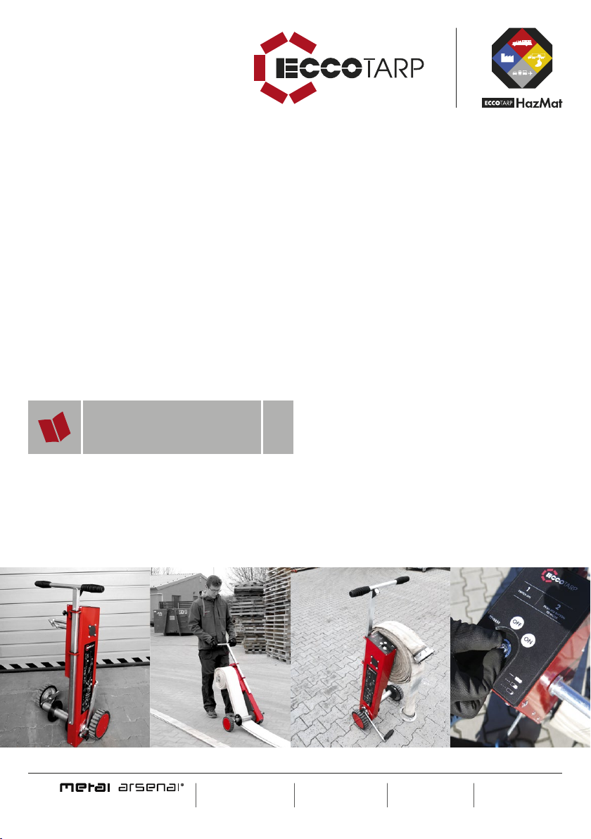
ET-ROLLER 5
Electric roller for fire hoses up to 5"
INSTRUCTIONS FOR USE US
T1 929-272-2336
Fax 212-683-8516
Eoce@eccotarp.com
www.eccotarp.us
Metal Arsenal s.r.o.
Owner of Eccotarp USA
trade mark
ECCOTARP USA, inc.
357 West 36th Street
New York, NY 10018
USA
Development
and
Production
This document„Instructions for use“ (hereinafter manual) is used to get acquainted with the
operation and characteristics of the ET-Roller 5 – Electric roller for re hoses up to 5" (hereinafter
„the roller“ or„the winder“), and describes themannerof its use and possible risks connected
withitsuse.
It contains important information about how to use the device properly so as to avoid injuries
andincrease its reliability and extend its lifetime.
This document must always be available in the place where the winder is used. Keep it together
with the device at all times.
The operator is responsible for using the device safely and in compliance with the instructions
inthis manual, which applies to any third persons as well. If you have any doubts about operating
the winder, please contact the manufacturer or an authorized dealer.
OFF
REVERSE ON
1
SWITCH ON
2
PUSH RED BUTTON
TO WORK
2
1
B
A
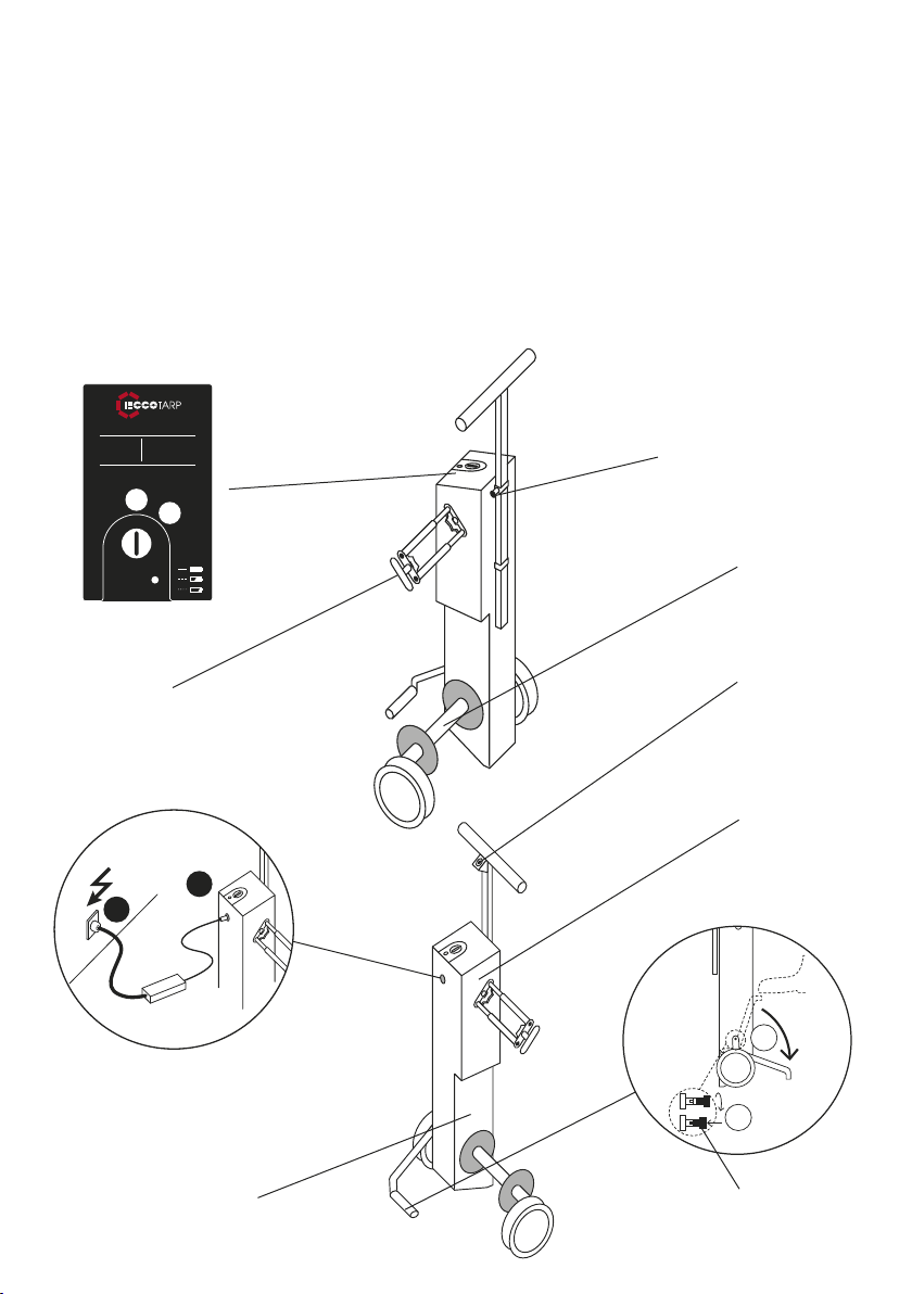
Control panel
Handle position
locking pin
Removable carrier fork
with a handle
Built-in battery
Guiding coil
Charging cable socket
Locking pin to secure the position
of the stabilizing fold-out chassis
Stabilizing fold-out chassis
WORK button
Built-in control unit
and motor

The package includes:
1× ET-Roller 5 – Electric roller for fire
hoses up to 5"
2× Removable carrier fork with
a handle (different sizes)
1× Winder charger 36 V
1× Instructions for use
Technical data
Safety instructions for use
When using the winder, observe these instructions as well as all the safety notices herein.
In the ET-Roller 5 package there are 2 sizes of Removable carrier fork with a handle to ensure the ability to wind different
couplings of fire hose up to 5".
1. The winder is only designed for winding and unwinding
fire hoses and for squeezing remaining water out
of hoses.
2. The winder may only be operated by 1 person (2 persons
in the event of unwinding).
3. The winder must be fully charged by the supplied
charger before it is used for the first time. The battery
reaches full capacity only after several charging cycles.
4. Disconnect the winder from the charger before use.
5. During the winding process, the handle must be held
with both hands and the stabilizing fold-out chassis must
be secured by a leg.
6. Caution! During winding, there is a risk of injury as
a result of clothes or limbs being caught in the carrier.
7. Before the hose is taken away from the carrier, the device
must be turned off.
8. Caution! The device is heavy.
9. Do not disassemble or modify the winder.
10. Never drop the device from a height.
11. Do not expose the device to temperatures over 104 °F for
extended periods of time.
12. Protect the device from direct sunlight.
13. If the winder is excessively hot, allow it to cool down and
only start using it after that.
14. Never throw the device directly into fire.
15. Never immerse the device in water or wash it with water
under pressure, and prevent water and moisture from
entering it directly.
16. Never attempt to charge a damaged winder.
17. In the event of injury resulting from improper use of the
winder take appropriate measures and if necessary seek
medical help.
18. The winder must not be handled or operated by children.
19. The device must not be disposed of with household/
municipal waste. When the device is past its
lifetime, it must be taken to a waste collection
point for environment-friendly disposal or returned
to the manufacturer.
20. The manufacturer confirms the product’s compliance
with EU directives.
Dimensions in use (w × d × h) 19 × 14.2 × 53.5 in
Dimensions of folded roller (w × d × h) 19 × 10.6 × 35.4 in
Height of roller with handle at the maximum 53.5 in
Package dimensions 27 × 13.4 × 36.6 in
Weight without fire hose 50.7 lb (incl. Li-ion battery),
60 lb (incl. VRLA battery)
Types of fire hoses that can be wound up to 5"
Optional accessories Material Dimensions (w × l × h) Weight
Hose protector stainless steel 9 × 14 × 6.3 in 2.4 lb
3
2
1
1. Insert the charger connector into the proper hole on the winder.
2. Insert the charger plug into a 100-240 V/50-60 Hz socket. The LED on the charger
lights up red. The winder is fully charged when the red indicator goes off and the
green indicator comes on.
The winder can wind about 15 092 ft. of wet A 110 type hose (230 times wound 66 ft. hose) when the 36V Li-ion battery is
fully charged.
The winder can wind about 11 483 ft. of wet A 110 type hose (175 times wound 66 ft. hose) when the 36V VRLA battery is
fully charged.
Outside the EU, the winders are delivered without batteries. To put the winder into operation, it is necessary to purchase
and install the recommended type of battery according to the enclosed Battery Replacement Instructions.
Specification of battery types
Battery replacement
Illustrated charging instructions
Accumulator battery Li-Ion VRLA
Operating voltage 36 V DC 36 V (3×12V) DC
Safety instructions for charging
1. The winder is completely discharged when a slow
rhythmical sound signal is heard and the WORK button
goes off.
2. Use only the supplied charger type to charge
the winder.
3. The range of permissible temperatures for charging
is between 32 °F and 104 °F. Outside this temperature
range the winder might be damaged or its lifetime
might be shortened.
4. No metal or other objects must be allowed to enter the
charger socket on the winder.
5. Never charge the winder in a wet
or humid environment.
6. Never charge the winder near sources of heat or on
flammable surface.
7. Make sure that the mains voltage corresponds to the
voltage on the charger’s data plate. Otherwise there is
a risk of electrical injury.
8. The winder and the charger become warmer during the
process. This is normal and it is not regarded as a defect.
9. Never cover the charger or the winder during charging.
10. The winder is fully charged when the red indicator goes
off and the green indicator comes on.
11. If the winder is not charged within 5 hours, interrupt
the charging process. Begin charging again
in 12 hours. If the problem persists, please, contact the
manufacturer’s service department.
12. If an unusual smell, overheating, colour or shape
change or any other abnormalities occur during
winder charging/operation, stop the charging process/
operation immediately.
13. Never use a damaged charger. If it is damaged, please,
send it to the manufacturer for repair or replacement.
14. Never open the charger. If there is a defect, please,
contact the winder manufacturer.
15. Battery replacement – if it is necessary to replace the
battery, it can be replaced with a new one by opening
the lid of the device marked„battery“ – instructions for
battery replacement are included.
16. Safety warning: never open the control unit and motor
cover in the upper part of the winder. By opening the
cover you lose warranty.
4

Preparation for winding:
1. The winder should be fully charged by the supplied charger before it is used.
The winder is designed so that it can be permanently connected to the charger while
stored. Use strictly the charger supplied by the manufacturer.
2. Disconnect the winder from the charger before use. Extend the handle into the optimal
position and transport the winder to the place of operation (winding).
3. Tilt and secure the stabilizing fold-out chassis: release the locking pin and turn it by 90 °.
That prevents the winder position from being automatically re-locked. Tilt the fold-out
LED is off – battery is fully charged
LED blinks in longer intervals – battery is half discharged
LED blinks in short intervals – battery is almost completely
discharged and must be charged
Important! One roller must be included with 3 batteries.
Winder battery charging indicator
Charging station specifications
Recomended baterries
Charging station 36 V
Imput voltage 88-264 VAC
Charging time 5 h
Model Yuasa NPH5-12 12V 5Ah Leaftron LTX12-5.4
(12V 5.4AH)
CSB HR 1227W CSB HRL 1225W CSB HR 1221W
Type VRLA Battery VRLA Baterry VRLA Baterry VRLA Baterry VRLA Baterry
Voltage 12V 12V 12V 12V 12V
Capacity 5Ah 5.4Ah 6.2Ah 5.8Ah 5.1Ah
Weight 3.5 Lbs 3.97 Lbs 4.34 Lbs 4.3 Lbs 3.97 Lbs
OFF
REVERSE ON
1
SWITCHON
2
PUSH RED BUTTON
TOWORK
Instructions for Winder Operation
Please, read the safety instructions and this manual before using the winder.
The winder is designed for winding fire hoses of sizes up to a diameter of 5" and a maximum hose length of 164 ft. Thanks to
its output it can also wind wet hoses (not filled with water). The winder can also be used for squeezing remaining water out of
fire hoses (see“Squeezing remaining water out of a fire hose”).
Hoses can be wound in two basic ways:
Winding with the winder stationary – STATIONARY method or while the operator walks – WALKING method.
Both methods make it possible to wind the hose from the centre to the end (option 1) or, thanks to the versatile carrier, from
the beginning to the end (option 2).
Although the operation is intuitive, recommended procedures for both alternatives are described below.
CLICK ON
PIN 90°
CLICK OFF
+ LOCK
PIN 90°
1 2
PULL OUT/
PUSH ON
1
5
chassis so that it is stabilized and turn the locking pin back by 90 ° and let it
slide into the locking hole.
4. Drain the water out from the hose. If, as a result of uneven surface, the hose is
full of water or contains large rest of water after firefighting intervention, see
“Squeezing remaining water out of a fire hose”on p. 11.
5. Prepare the hose in the appropriate position according to how you want to
wind it for storage – see the instructions below („option 1”or„option 2”).
5.1 Option 1: The hose can be folded in half and pulled by the folded
end towards the winder (see figure X). When folded, both parts
of the stretched hose must be put on each other and aligned
and the metal couplings must be positioned in such a way that
the coupling of the upper half lies over the end of the lower half
of the hose. The rule for the overlap length is 1.6 ft. of overlap
per each 33 ft. of folded hose (e.g. with a 66 ft. hose – 33 ft. after
being folded – the upper coupling will overlap the
lower one by 1.6 ft.).
5.2 Option 2: Make the complete length of the hose
straight. An A or B size hose will be reliably wound if
the coupling is put into the jaws of the carrier fork,
which will hold the protrusions on the flange (see
figure Y). If thinner, C or D size hoses, are
to be wound, simply pass the coupling
through (see figure Z). In the ET-Roller 5
package there are 2 sizes of Removable
carrier fork with a handle to ensure the
ability to wind different couplings of fire
hose up to 5“.
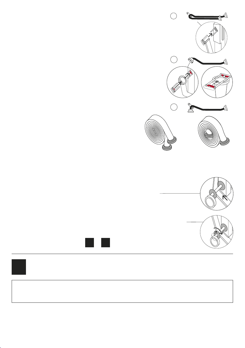
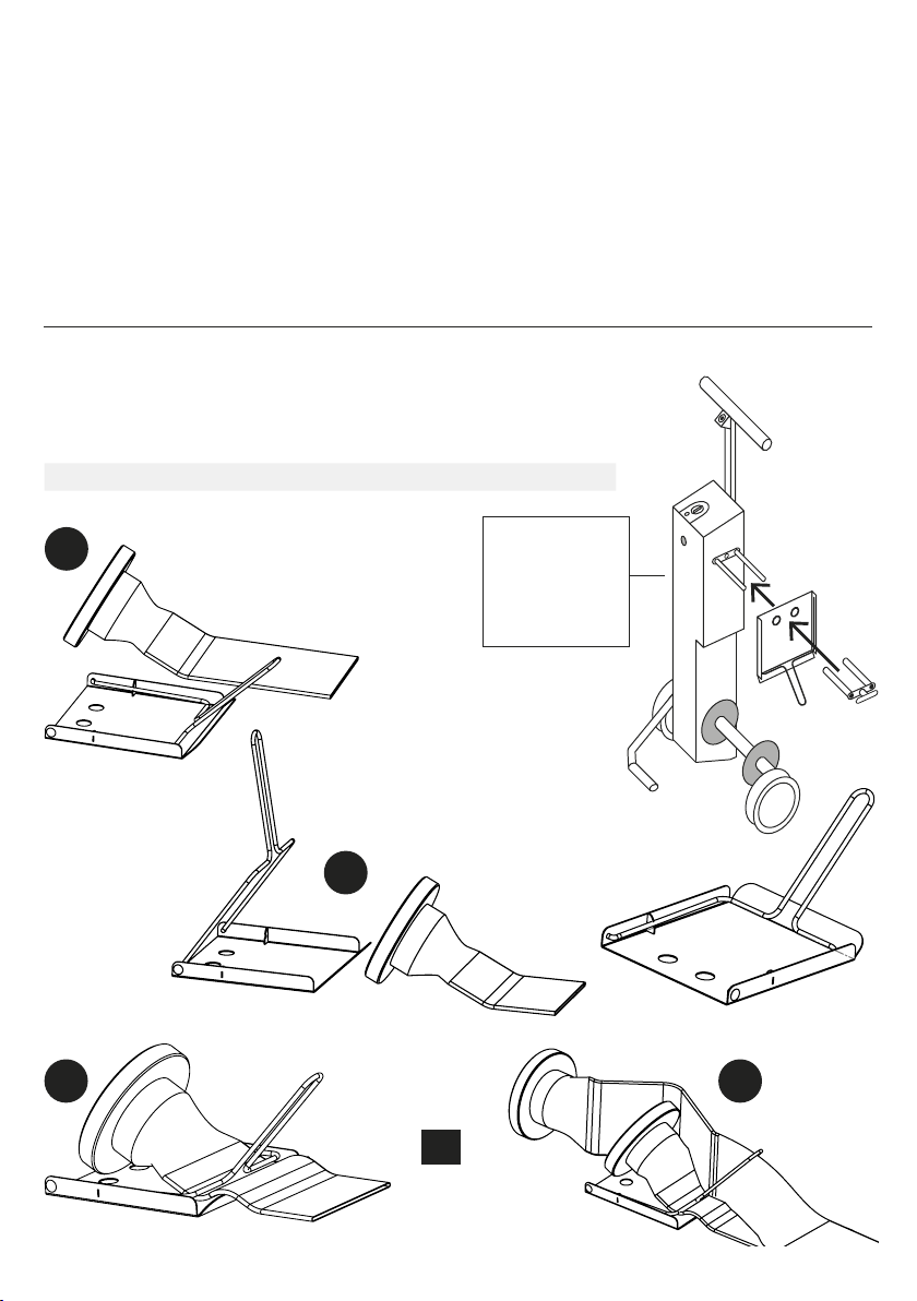
6. Pass the end of the hose or the end of its folded part under the guiding coil.
7. Remove the removable fork from the carrier
and put the end or folded centre of the straightened, aligned hose on it according to one of
the alternatives described in section 5 hereof.
8. Using a black plastic plate, adjust the width of the guiding coil to the width of the hose by
turning it on the core of the coil.
9. Switch the winder to the ON position on the control panel.
10. Then follow one of the ways below ( 2or 3)
2Hose winding STATIONARY METHOD
(winder stands and the hose approaches during winding)
1.
2.
2.1 Use both hands to get hold of the winder handles and press the locked tipping part of the stabilization
chassis to the ground in the lower position with your right foot. Turn the switch on the control panel
clockwise into the ON position. The control features will be illuminated in red and the winder is ready
for operation.
Caution! During this procedure, the end of the hose, close to the coupling, which is moved on the surface, may
become chafen through. That is particularly risky in the case of hard surface, such as concrete, paving, etc. Therefore, we
recommend using a“hose protector“ (see optional accessories on page 12) for the free part of the hose end.
Z
Y
X
Hose wound according
tog.X–seeoption1.
Hose wound according
tog.Y–seeoption2.
ADJUST
ADJUST
6
2.2 Push the WORK button on the winder handle.
2.3 The winder starts winding the hose at a speed that
gradually decreases so that the winding speed is safe
even with increasing diameter of the winding. Towards
the end of the winding process, when the couplings get
close to the lower guiding coil, it is recommended that the
hose should be wound in a controlled manner by pressing
the WORK button intermittently until the couplings
come safely close to the guiding coil. After that the hose
couplings must be manually passed under the guiding coil
(tilting the winder to a side in the case of the largest hoses)
and with extreme care, the rest of the hose can be wound by
pressing the WORK button shortly. If the “hose protector“ is
used during winding, it must be removed from the hose end
before passing the hose under the guiding coil so that the
winder does not get damaged.
2.4 When winding is completed, turn the winder OFF.
2.5 Remove the wound hose with the removable part of the carrier from the winder and put it away for
further handling. Remove the removable part of the carrier from the centre and put it back on the carrier.
The hose is now ready to be stored or used.
2.6 When you have finished working with the winder, connect it to the charger so that it is available with its
battery fully charged at all times. After the battery is completely charged, the charger is automatically
turned into standby mode, which prevents the battery from self-discharge.
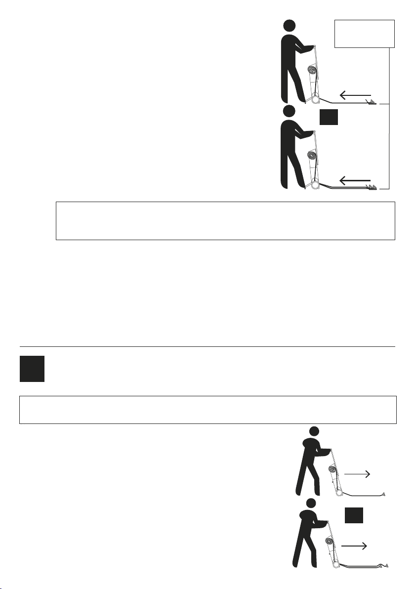
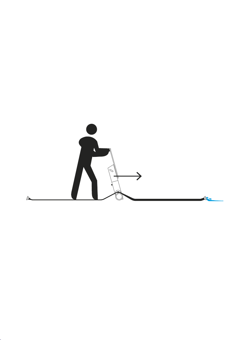
3Hose winding WALKING METHOD
(the user walks forward with the winder and the hose is stationary on the ground
while being wound)
3.
3.1 Tilt and secure the stabilizing fold-out chassis: Release the locking
pin by hand, turn it 90° to prevent it from engaging automatically
again and locking the position. Tilt the chassis into the transport
position and secure it by turning the pin 90° and letting it slide into
the locking hole.
3.2 Turn the switch on the control panel clockwise into the ON position.
The control features will be illuminated in red. Press the illuminated
WORK button in the middle of the handle and start walking with the
winder immediately towards the free end of the hose. Adapt your
walking speed to the winding speed.
3.3 The winder starts winding the hose at a speed that gradually
decreases so that the winding speed is safe even with increasing
Note: The WORK button can be released at any time during operation in order to stop winding. After it is
pushed again, the winder continues working with the lower revs which it had when it was stopped (see
Graph 1).
If you need to protect the hose against damage during winding without using the“hose protector“, it can be wound
when the user is walking forward with the winder and winding the lying hose.
or
or
Hose protector
– see p. 12
7

CLICK ON
PIN 90°
CLICK OFF
+ LOCK
PIN 90°
PULL OUT/
PUSH ON
1 2
A
B
B
A
PULL
OUT
3
A4
B
A
C
ADJUST
5
Y
X
Z
Illustrated instructions for winder operation
diameter of the winding.Towards the end of the winding process, when the couplings get close to the
lower guiding coil, it is recommended that the hose should be wound in a controlled manner by pressing
the WORK button intermittently until the couplings come safely close to the guiding coil. After that the
hose couplings must be manually passed under the guiding coil (tilting the winder to a side in the case
of the largest hoses) and with extreme care, the rest of the hose can be wound by pressing the WORK
button shortly.
If the“hose protector“ is used during winding, it must be removed from the hose end before passing the
hose under the guiding coil so that the winder does not get damaged.
Note: The WORK button can be released at any time during operation in order to stop winding. After it is
pushed again, the winder continues working with the lower revs which it used when it was stopped (see
Graph 1).
3.4 When winding is completed, turn the winder OFF and tilt the stabilizing fold-out chassis so as to secure
the winder while removing the hose from the carrier.
3.5 Remove the wound hose with the removable part of the carrier from the winder and put it away for
further handling. Remove the removable part of the carrier from the centre and put it back on the carrier.
The hose is now ready to be stored or used.
3.6 When you have finished working with the winder, connect it to the charger so that it is available with its
battery fully charged at all times. After the battery is completely charged, the charger is automatically
turned into standby mode, which prevents the battery from self-discharge.
Tilting and securing
the stabilizing fold-out chassis
Placing hose into
hose carrier
Manners of securing
hose in carrier
ADJUST
Z
Y
X
8

SAFETY FUNCTIONS OF THE WINDER
Certain safety features influence some of the winder’s reactions during
the work:
1. Stopping the winding – If the motor becomes overloaded unexpectedly (e.g. as a result of the hose being obstructed
or stepped on), the winding process is interrupted immediately, the WORK button starts blinking and a fast sound signal
is heard. If you only release the winder’s WORK button (without turning the main switch to the SWITCH OFF position),
then, after the cause of motor overloading is removed and WORK is pushed again, the winder continues working with
the revs which it used at the time of being stopped (see Graph 1). However, in this case of forced interruption, the
controlling software needs a few seconds before it can resume the winding process.
2. Motor overheating – The system has a safety feature that prevents overheating. If the motor becomes excessively
hot (e.g. during work under extreme temperatures), the battery is automatically disconnected. The reason is battery
safety. Place the machine out of reach of the heat source (e.g. in shade). The machine can be turned on again after
it cools down.
3. The OFF-ON switch and the WORK button –
The winder is fitted with a smart revs control
feature for your convenience and safety. Every
time the OFF-ON switch is used, the“Winding”
program is activated (see Graph 1 and 2). It
shows the course of the carrier’s revolving
speed. That happens so that the winding revs
are fast with a small spool diameter and the
winding speed remains approximately the
same and safe while the diameter becomes
larger. When winding is stopped – the WORK
button is released – the winding program is
interrupted. When WORK is pressed again, the
winding speed returns to the previous speed in
a few seconds (see Graph 1).
4. Interrupting the winding process by using
the OFF-ON button – It is clear from the
description above that if the winding process
is interrupted and the OFF-ON button is
used, the winding function starts again at the
beginning. That means that if the winding
process is interrupted and the winder is turned
OFF and then ON again, the highest revolution
speed is activated by pressing the WORK
button (see Graph 2). In spite of that it is still
possible to work safely: you can control the
revs by pressing WORK repeatedly.
Winding speed
Graph 1
OFF–ON –
pressing of WORK
Interruption –
pressing of WORK
Time
Winding speed
OFF–ON –
pressing of WORK
Interruption – ON–OFF –
obstacle removed OFF–ON –
pressing of WORK
Time
Graph 2
PUSHSWITCH
ON
A B
6
OFF
ON
7
Winder activation
Removing carrier fork
from wound hose
9
Smart winding
Your winder has a smart motor control which allows you to adjust the fire hose winding speed. The reason is your
convenience and safety as well as battery protection.
1. How does it work? After WORK is pressed, the motor begins winding at zero speed. Then it switches to the
highest revs very quickly and while the hose is gradually being wound, it starts lowering the revs so that with the
increasing diameter of the wound hose, the winding speed for the free end of the hose remains safe.
2. Release WORK before completing the winding process and by pressing it intermittently you will achieve the lowest safe
winding speed (see Graph 1).
3. Overloading – if the hose gets stuck or stepped on, or for other reasons, the winding force may become excessively high.
In such a case, the system automatically disconnects the battery and warns the user by a fast warning sound and by the
WORK button blinking. After the WORK button is released and the obstacle removed, the machine is ready to be used
again in a few seconds.
4. Overheating – the machine has a recommended working temperature range. When the highest safe temperature
(140 °F) is exceeded, the battery is automatically disconnected from the machine. The reason is battery protection
against overheating. After cooling down, the machine is ready to be used again.
5. Battery discharged – if battery capacity decreases under the safety limit, the battery is disconnected from the device,
a slow warning signal is heard and the WORK button’s light indicator goes off. The reason is battery protection against
destruction. After the battery is recharged, the machine is ready to be used again. The machine comes with the original
charger, which can fully recharge the battery in about 5 hours. The machine is designed in such a way that the charger
can be connected to the winder permanently (charging is automatically stopped when the battery is fully charged).
REVERSE function
By turning on the REVERSE function on the control panel and pressing the WORK button, the reverse run of the carrier is
activated. This function is mainly used for controlled unwinding of an already wound fire hose. Two persons are needed for
this function to be used. One person controls the winder (switching on REVERSE and pressing WORK) while the other person
grips the metal couplings of the wound hose and moves away from the winder in accordance with the winder revs. When
this function is used (both with the unwinding interrupted and uninterrupted), the fire hose is unwound at high speed all the
time (see Graph below). Therefore, it is necessary to be extremely careful.
Squeezing remaining water out of a fire hose
Unwinding speed
OFF–REVERSE –
pressing
of WORK button
Interruption –
pressing
of WORK button
Time
10
1. The winder must be turned off – the OFF position on the control panel.
2. Pass one end of the hose over the lower guiding coil so that you can step on this hose end.
3. If the stabilizing fold-out chassis is tilted out, tilt it down so that the winder can stand on it without being supported.
4. Tilt the winder towards yourself and proceed slowly with the discharging (downhill, if possible) so that the hose is rolled
over the coil, which pushes the water in the hose forward, towards the other end, where the water flows out of the hose.
The process of stretching the hose over the coil and of the water flowing out can be intensified by walking on the hose
throughout the process.
5. Make sure that no objects that might prevent the water from flowing out lie on the hose during the process.
6. After the water discharging process is finished, the hose can be placed on the removable carrier fork and wound into
shape for storage as described in the“Instructions for winder operation” chapter.
11
228
220
352,1
160
Instructions for winder charging and storing
1. Store the winder in a dry place.
2. If the winder is not to be used for a long time, it should be stored at room temperature (66–73 °F).
3. The winder system is designed in such a way that the charger can be connected to it permanently and the battery
is safely recharged without any risk of damage. As a result, the charger can be connected during storage as well.
4. When the winder is completely discharged, the system is automatically disconnected from the battery so that the
battery is not completely destroyed. Therefore the battery must be recharged as soon as possible.
5. If stored for a long time without the charger connected to it, the battery must be fully recharged once a year so as
to prevent it from being totally discharged.
Recommended optional accessories
Hose protector Material Dimensions (w × l × h)
for hoses of up to size 5" stainless steel 9 × 13.9 × 6.3 in
We recommend
storing the hose
protector hung
on the winder
carrier fork.
1
2
3 4
or
12

Important contact information
Qualified service:
ECCOTARP USA, inc.
357 West 36th Street
New York, NY 10018
USA
office@eccotarp.com
T: 1 929-272-2336
Repair
Any repair work must always be done by the manufacturer’s qualified personnel. In order to report any faults, spare parts
orders or complaints, please contact only our qualified service department.
Warranty conditions
The warranty period is stated in the warranty certificate, which is delivered with the product. The warranty period is
24 months and begins on the day indicated in the warranty certificate. The warranty does not apply to the normal wear
and tear (e.g. gradual decrease in battery capacity) or to damage caused by improper use or non-compliance with the
information provided in these Instructions for Use.
Disposing of a damaged device or its parts
The device or its parts must not be disposed of with household/municipal waste. At the end of its lifetime, the device must
be taken to a waste collection point for environment-friendly disposal or returned to the manufacturer. A charger, that is past
service, must be taken to an electric waste collection point or returned to the manufacturer.
EU DECLARATION OF CONFORMITY No. 01032020/M
Metal Arsenal s.r.o., Poděbradova 1920, 289 22 Lysá nad Labem, Czech Republic, hereby declares, at its sole liability, that the
following product
ET-ROLLER 5
Electric roller for fire hoses up to 5"
(A winder intended for winding fire hoses with couples of the maximum size of 5" and maximum length of 164 ft. It includes
a 36V DC battery charger.) complies with applicable harmonized standards of the European Union.
The above is verified according to Government regulations no. 118/2016 Sb., which is equivalent to a Council Directive
2014/35/EU Government Regulation no. 117/2016 Sb., which is equivalent to a Council Directive 2014/30/EU, ČSN EN 60335-
1 ed. 2, ČSN EN 61000-6-3 ed. 2, ČSN EN 55014-1 ed. 4.
13

Notes
14

Pictograph meanings
Observe the Instructions for
use for ET-Roller 5.
During the winding process, the
handle must be held with both
hands and the stabilizing fold-out
chassis must be secured by a leg.
Caution! During winding, there is
a risk of serious injury as a result of
clothes or limbs being caught in
the carrier.
Do not wash the
machine with water
under pressure.
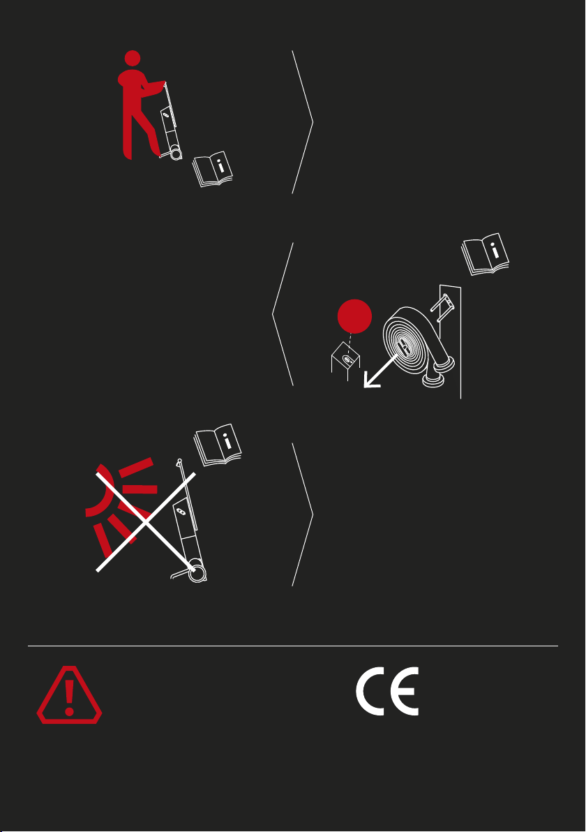
1 person only
1. 2.
OFF
Caution! Indicates imminent
danger. Not observing this
warning may cause death
or serious injury.
Before using the winder, read all the safety warnings in this manual. The illustrations in this manual may not fully correspond
to the supplied product. Their purpose is to help you understand the text better. The content of this manual may be changed
without prior notice.
Confirmation of the
machine’s compliance
with EU regulations.
The winder may only be
operated by 1 person.
Before the hose is taken away
from the carrier, the device
must be turned off.
Protect the device from direct
sunlight and do not expose it to
temperatures higher than 104 °F
for extended periods of time.
Table of contents
