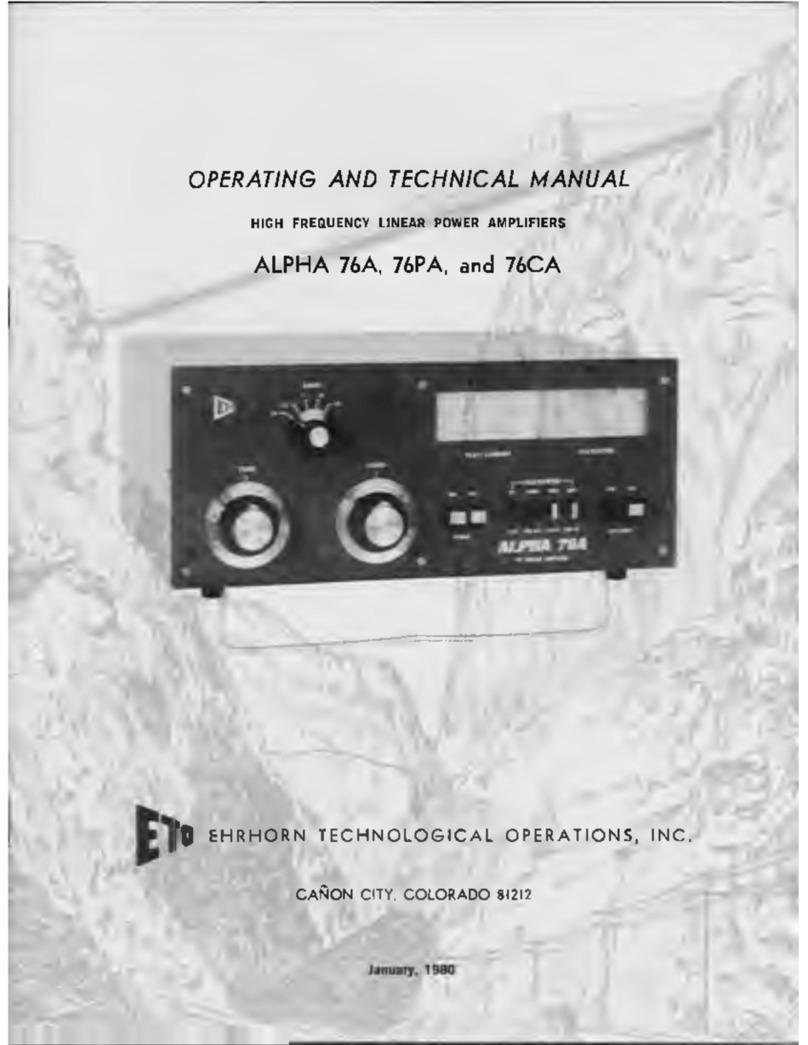
Ehrhorn Technological Operations ALPHA 86 User manual

OPERATING & TECHNICAL
MANUAL
ALPHA 86
HE LINEAR POWER AMPLIFIER
EHRHORN TECHNOLOGICAL OPERATIONS, INC
4975 NORTH 30TH STREET
COLORADO SPRINGS, CO 80919
COPYRIGHT 1990 BY E.T.O., INC.

OPERATING & TECHNICAL
MANUAL
ALPHA 86
HF LINEAR POWER AMPLIFIER
NOTE
The schematic dia rams and text in this manual describe the latest production version of the ALPHA 86
amplifier, includin early units which have been factory-modified.
Minor desi n chan es (which do not affect overall circuit desi n, specifications, capabilities, or operat
in procedures) typically are made on a continuin basis over the life of the product. Thus most ALPHA 86's
will vary to some de ree from details shown herein.
We stron ly recommend that you retain for reference and comparison the schematic dia rams
ori inally provided for your ALPHA 86.
Please contact ETO ALPHA products customer service if you need further information.

CONTENTS
GENERAL Service Assistance 1
Initial Inspection 1
10 and 12 Meter Operation 1
SECTION 1 Introduction 2
General Description 2
Specifications 2
SECTION 2 Preparation for Operation 3
Transformer Installation 3
Shippin Hardware Removal 3
120 Volt Modification 4
Transformer Installation - Pictorial 5
SECTION 3 Transceiver Connection 6
Transceiver Connection - Pictorial 7
SECTION 4 Operation 8
Control Functions 8
Switches 8
Meterin 8
Tune-Up Procedure 8
Hi h and Low Power Tune-Up 10
Reflected Power Protection 11
ALC 11
Initial Control Settin s - Table 1 12
SECTION 5 Operatin Notes 13
Panel Lamp Replacement 14
SECTION 6 Troubleshootin Tips 15
Receive Fuse Replacement 17
SECTION 7 Theory of Operation 18
SECTION 8 Schematics 23
#
t

GENERAL
SERVICE ASSISTANCE
To help you secure technical assistance without wasted lon distance calls, ETO has established a
special SERVICE telephone line which will be answered only when a qualified technician is available to help
you immediately.
The special service number is (719) 599-3861 (599-ETOl). If your call is not answered, it means that no
qualified technician is free to talk with you at the moment. Please wait a few minutes and try a ain. Our
business hours are from 8:30AM to 4:30 PM Mountain Time Monday throu h Friday. If your call does not
relate to service or other technical matters, our business office staff will be happy to help you at our main
office telephone number, (719) 260-1191.
INITIAL INSPECTION OF YOUR ALPHA 86
When you remove the top cover to install the power transformer (see p. 5) make sure the tubes are
firmly seated in their sockets and the tube anode connectors (silver strap rin s) are firmly attached to the tube
plate caps. If the connectors are not attached the tubes may be irreparably dama ed immediately upon
application of RF drive to the amplifier.
The red silicone rubber chimneys installed on the 3CX800A7 tubes are absolutely essential parts of the
coolin system. Make sure the chimneys are strai ht (vertical) and firmly installed. The bottom ed e of each
chimney must be flush a ainst the tube deck, completely coverin the airflow slots. Tube coolin air must exit
throu h the tube anode fins; it must not be allowed to escape around them. Failure to ensure adequate and
proper coolin airflow will result in severe tube dama e not covered under warranty!
TEN METER OPERATION
FCC rules permit appropriately licensed amateurs to modify their own amplifiers for operation on 12
and 10 meters. We stron ly recommend that you contact ETO customer service before attemptin any
modification. If a photocopy of your amateur radio operator's license is sent with the warranty re istration
card, easy-to-follow instructions will be sent to you at no char e. We are not permitted to perform this
modification for you at ETO.
1
»

SECTION 1 - INTRODUCTION
1.1 General Description
The ALPHA 86 is a self-contained, HF linear power amplifier capable of continuous operation at a
power output of 1500 watts PEP, keyed CW, SSTV, RTTY, or AM, with no time limit (rated for continuous
commercial service, "CCS"). Units delivered within the USA and its territories and possessions are manually
tunable over the frequency ran e of 1.8 to 22 MHz. They may be user-modified to extend covera e to 29.7
MHz. Units delivered elsewhere cover 1.8 throu h 30 MHz. Performance is optimized for amateur bands.
The ALPHA 86 is capable of hi h-speed, full break-in CW (QSK) when used with a suitably-desi ned
transceiver. Note: the term "transceiver" includes suitable transmitter-receiver combinations, such as the
Collins S-Line and Drake R4C-T4XC, etc. The ALPHA 86 is fully compatible with CW, AMTOR, or PACKET
modes.
12 Specifications
1.2.1 Frequency Covera e: 1.8-22 MHz (domestic units); 1.8-30 MHz (export units).
1.2.2 Power Output: 1500 watts all modes includin continuous carrier, CCS.
1.2.3 Drive Power: 50 to 70 watts nominal for rated output.
1.2.4 Power Gain: approximately 15 dB, equivalent to a power increase of thirty times.
1.2.5 Input Impedance: 50 ohms nominal, unbalanced VSWR < 2:1; switched pi-networks for each band.
1.2.6 Output Impedance: 50 ohms unbalanced.
1.2.7 Maximum Load VSWR: 2:1 at full rated power output.
1.2.8 VSWR Trip: automatic for reflected power of >200 watts.
1.2.9 Intermodulation Distortion: 35 db below rated output.
1.2.10 Harmonic Output: < -55 dBc amateur bands; < -50 dBc elsewhere.
1.2.11 CW Break-in (QSK): PIN diode T/R switchin , 4 millisecond maximum switchin time.
1.2.12 Tube Complement: two Eimac 3CX800A7 ceramic-metal triodes.
1.2.13 Coolin : full cabinet ducted forced air usin cushion-mounted centrifu al blower.
1.2.14 Automatic Level Control (ALC): ne ative- oin (from zero) DC volta e derived as a function of
rid current. May be used to limit exciter output to prevent amplifier overdrive.
1.2.15 Primary Power: 220-240 volts AC, 60Hz (50-60 Hz export and non-type accepted models), fused
at 20 amperes. May be field-modified for 110-120 volt operation at reduced power (maximum
fuse size 20 amperes).
2

1.2.16 Power Transformer: Tape-wound Hipersil®core, 3.5 kVA CCS.
1.2.17 Protective Devices: primary and step-start fuses, primary AC interlock, hi h volta e crowbar,
plate overcurrent trip, T/R mis-sequence trip, and reflected power trip.
1.2.18 Status Indicators: operate, standby, wait (initial tum-on time delay), overdrive (excessive rid
current), SWR (reflected power tripout), and T/R fault.
1.2.19 Meterin : full-time LED bar raphs display forward and reflected power and rid current; select
able plate volta e, plate current, and tune function.
1.2.20 Size:7.5"H x irW x 15”D (19x 43x 38cm).
1.2.21 Wei ht: 66 lb. (30 K ) net, 70 lb (32 K ) shippin in two cartons.
Note: ETO reserves the ri ht to chan e desi n and/or specifications without notice or obli ation.
SECTION 2 - PREPARATION FOR OPERATION
2.1 Transformer Installation
Remove the top cover. CAUTION: Do not remove the two screws in the center of perforated areas of
cover! Install the power transformer in the amplifier chassis. Note orientation of transformer wires as shown
in drawin s 1 throu h 4, pa e 5. USE CAUTION! The power transformer will dama e wires or components
if allowed to rest on them. Lift the transformer just hi h enou h to clear the ri ht side chassis lip and then
move it sideways into the chassis. The transformer base plate must clear all components and wirin and, in
some units, the two RCA type jacks on the back chassis wall. It must slide underneath these two RCA jacks
and not pinch the chassis wirin . Four tapped bolt holes are provided in the transformer base plate. Mount
in hardware is supplied with the power transformer. This hardware is inserted into the base plate from
underneath the chassis. Mate transformer wirin connectors per Fi ure 1, pa e 5.
22 Inspection - Tubes & Chimneys
While the top cover is removed, make sure the tubes are firmly seated in their sockets and the tube
anode connectors (silver strap "rin s") are ti htly attached to the tube plate caps. If the connectors are not
attached the tubes may be irreparably dama ed immediately upon application of RF drive to the amplifier.
The red silicone rubber chimneys installed on the 3CX800A7 tubes are absolutely essential parts of the
coolin system. Make sure the chimneys are strai ht (vertical) and firmly installed. The bottom ed e of each
chimney must be flush a ainst the tube deck, completely coverin the airflow slots. Tube coolin air must
exit throu h the tube anode fins; it must not be allowed to escape around them. Failure to ensure adequate
and proper coolin airflow will result in severe tube dama e not covered under warranty.
23 Shippin Hardware Removal
The blower motor is secured to the back chassis wall for shipment. The shippin hardware should be
removed for quietest blower operation. Follow the instructions printed on the label directly beneath the
blower bearin cutout (round hole) on the back wall. The hardware should be reinstalled whenever the
amplifier chassis is packed for shipment.
3

2.4 Primary Power -120 Volt Modification
The ALPHA 86 is factory set up for operation from a 220-240 volt source. It is fused at 20 amperes. A
dedicated branch circuit to the amplifier, usin #10 AWG copper wire or equivalent (with a current capacity
of at least 30 amps) is recommended for best results. To reconfi ure the ALPHA 86 for 110-120 volt operation,
locate the six screw terminal block to the ri ht of the center partition on the back chassis wall. As shipped
from the factory lu s 2 and 3 (numbered from the left) are jumpered. Move the strap to jump lu s 1 and 2.
Another strap (supplied with the spare fuse kit) is installed across lu s 3 and 4, and a third across lu s 5 and
6. Note that 120 volt operation from a typical 20 ampere household circuit (with no other loads connected to
it) may limit amplifier power output to around 1000 watts.
2.5 Replacin Cover
Tilt the top cover down sli htly at the front to allow its front ed e to slide underneath the front panel
trim piece. Slide the cover over the chassis and ali n the screw holes. The chassis may warp sli htly after the
power transformer is installed. Do not tighten any of the screws until all are started.
2.6 240 Volt Primary Connections & Amplifier Groundin
The ALPHA 86 chassis is directly connected to the reen power cord conductor. The reen conductor
must be connected to the power plu safety " round" (or neutral) pin. The black and white power cord wires
connect to the two 240V "hot" blades of the AC plu (either wire to either blade is okay).
A separate round lu (with win nut) is provided on the rear of the chassis. Connection at this point
should be made to a ood RF earth round such as a copper water pipe or driven rod, via heavy braid or
strap.
4

FIGURE 1
Transformer Installation
2
r
Lnil Ï
4
V IR E S OMITTED FOR CLARITY
6RED
ORANGE
BLACK
5

SECTION 3 - CONNECTION TO THE TRANSCEIVER
ALPHA 86 interconnections to the station transceiver are shown in fi ures 2 and 3 on pa e 7.
3.1 Coax Types & Connectors
Connect the transceiver RF output to the ALPHA 86 RF input with 50 ohm coaxial cable-type RG-58C/U
or equivalent Coaxial cable used between the ALPHA'S RF output and antenna should be type RG-8A/U,
RG-213/U, or equivalent hi h quality type. Type RG-8X cable is not recommended. Su ested connectors
are Amphenol 83-1SP male UHF type (with reducin fittin type UG-175 for use with RG-58C/U).
32 T/R Switchin
For transmit/receive switchin the ALPHA 86 requires a relay contact closure on transmit across its
RELAY jack (center pin to chassis). This control function is supplied by the transceiver, usually from a
dedicated relay that is normally open in receive and closes in transmit.
The relay contact must close before RF drive is applied. The ALPHA 86 protective circuitry will not
allow the amplifier to "hot switch" with RF drive applied. Attemptin to force a hot switch will cause
protective circuitry to lock out the receive to transmit chan e over. If this happens the "T/R" fault LED will
illuminate. It may be reset by removin drive, unkeyin the transceiver, and switchin the ALPHA from
operate (OPR) to standby (STBY) and back to operate (OPR).
A few (mostly older model) transceivers may enerate an RF transient (spike) when keyed. This spike
may activate the ALPHA 86's excessive rid current protection, in which case modification of the transceiver
will be necessary. For specific instructions contact the ETO customer service department.
Fi ure 2 should be used with late model transceivers such as those listed below, and will allow the full
capabilities of the ALPHA 86 includin break-in (QSK) operation, to be enjoyed. Suitable transceivers
include at least these (as of 9/90):
*
Kenwood TS-9405, TS-950S/D, TS440S, and later production versions of the TS-930S and TS-4305
Icom IC-735, IC-751, IC-751 A, IC-761, IC-765, and IC-781
Yaesu FT-757, FT-767, FT-1, and FT-1000
Fi ure 3 shows a switchin arran ement that may be used to facilitate chan in from conventional SSB/
VOX or PTT to CW break-in operation with older transceivers that have inappropriate T/R sequencin . The
desired mode of operation is selected by the external DPDT switch. QSK-capable transmitters of older desi n
may also require connection per Fi ure 3.
For transceivers or transmitters not mentioned above, try connection per Fi ure 2 first. If T/R faults
occur, try Fi ure 3.
33 ALC
The ALPHA 86 enerates a rid-current-derived, ne ative- oin (from zero) DC control volta e that can
be fed back to most transceivers to avoid overdrive. To take advanta e of ALC, connection must be made to
the ALPHA 86 rear panel ALC jack.
Any rid current excursion above approximately 70 mA will "tri er" the ALC. At about 100 mA, ALC
output is nominally -10 VDC. If the transceiver requires less volta e a 100 kohm potentiometer may be
connected across the center pin of the ALC jack to chassis. The potentiometer wiper will provide an adjust
able "feed" to the transceiver. While drivin the amplifier the potentiometer can be adjusted to limit trans
ceiver output to keep the amplifier rid current less than 100 mA.
6

FIGURES 2 & 3
Connection to the T ransceiver
FIGURE 2. ALPHA 86 Interconnections for Normal
V X, PTT, AND QSK peration,
TD ANT
KEY/AUX o
RF IN ALC
RELAY
PTT
TRANSCEIVER
ALC RF UT RELAY
PHDND PATCH
o
RG-58C/U
o
'PHDND' PATCH CDRD
FIGURE 3, Alternative Method fo r Switching Between
Conventional SSB PTT or VDX and CV Break-in-See text
MIC PTT
KEY/AUX
C
RELAY
C
ALP
P
HA-86
KEY SSB
TRANSCEIVER
KEY
■ o
RELAY
CV
DPDT SWITCH
7

SECTION 4 - OPERATION
4.1 Tune-Up Control Functions
BAND - Selects tunin ran e; scale indicates principal amateur band covered. Frequency ran es in
MHz are displayed on commercial models.
TUNE - Selects operatin frequency. In eneral, hi her frequency bands tune toward the"0" end of the
dial scale, while lower bands tune toward the "50" to "100" end.
LOAD - Sets amplifier plate loadin and determines the power input level at which best efficiency and
linearity are achieved. In eneral, loadin is heavier at reater scale settin s and hi her frequency
bands load toward the "50" to "100"end of the vernier dial scale. Lower bands load toward the "0"end.
42 Switches
POWER ON: Depress momentarily to apply primaiy AC power to the amplifier, or to "reset" power if
the plate overcurrent relay has tripped.
POWER OFF: Depress momentarily to remove primary AC power.
OPR - STBY: Operate (OPR) places the amplifier in line to the antenna. With the amplifier turned off, or
in Standby (STBY) and durin warm up (before the WAIT LED oes out), the amplifier remains
bypassed, with the exciter connected directly throu h to the antenna.
HI - LO: LO selects reduced plate volta e for tunin or low power operation to about 1000 watts output.
HI selects hi h plate volta e for full power operation.
43 Meterin
Separate LED bar raphs provide instantaneous full-time display of peak RF OUTPUT (to 2.3 kW), GRID
CURRENT (to 150 mA), and REFLECTED POWER (to 250 watts).
A fourth, switch-selected LED bar raph monitors these additional functions:
TUNE: Facilitates amplifier tune-up. Tunin is optimized when one of three center LEDs is illumi
nated. ( See subsection 4.)
Ip: Plate current, 1.5 amperes full scale (approximately 75 mA per se ment).
HV: Plate volta e, 3000 VDC (150 V per se ment).
4.4 Tune-up Procedure
4.4.1 Objective
The objective of tune-up is to adjust the amplifier (and the drive applied to it) to obtain maximum
efficiency and linearity at the desired output power (or in rare cases with the maximum available drive
power, if that is the limitin factor).
When the amplifier is adjusted for maximum attainable RF output with a specific fixed level of drive
power, it inherently yields the best combination of efficiency and linearity possible at that particular drive level.
If a reater drive level than that used for tune-up is applied, the result will tend to be flattoppin ,
off-frequency "splatter," and excessive amplifier rid current.
8

4.4.2 Grid Current
Grid current falls off rapidly when drive power is too low and rises abruptly when drive power is too
hi h. GRID CURRENT IS THE SINGLE BEST INDICATOR OF PROPER AMPLIFIER OPERATION, In
the ALPHA 86 rid current should never exceed 70 to 80 mA under normal CW/SSTV/RTTY carrier or SSB
peak conditions. If the rid current reaches 80 mA before the desired value of plate current is obtained, do
not increase drive further! When operatin voice SSB, rid current should peak in the ran e of 30-50 mA.
The threshold of the O'DRV (overdrive) indicator LED is set at 120 mA rid current. If this indicator
flashes at any time reduce transceiver output immediately!
Excessive drive creates excessive rid current. Either reduce drive or increase amplifier loadin to take
advanta e of this excess drive to produce more output power.
4.43 ALC
The ALPHA 86 enerates ALC as a function of rid current rather than RF drive. This provides positive
tube protection a ainst possible dama e, as any excessive rid current excursion will be self-limitin . This
protection will be provided for the tube rids only when an ALC connection is made from the ALPHA 86 to
the transceiver. The ALC volta e enerated by the ALPHA 86 is not applied internally and cannot control the
amplifier itself.
4.4.4 Initial Tune-Up
IMPORTANT: The forward and reflected power LED bar raphs are peak-readin . All other bar raphs
display avera ed readin s.
BEFORE INITIAL TUNE-UP, MAKE SURE A SUITABLE ANTENNA OR DUMMY LOAD IS
CONNECTED TO THE ALPHA 861 Leave the amplifier turned off or in standby, and use exciter power only
for a forward versus reflected power check. If reflected power is less than ten percent of forward power, the
VSWR is lower than 2:1 and it is safe to proceed.
Turnin on the ALPHA 86
1) Select LO plate volta e (HI-LO switch).
2) Place the OPR-STBY switch in STBY (standby).
3) Depress Power ON.
If any of the followin does not occur, depress power OFF switch immediately and investi ate before
proceedin :
1) The blower starts.
2) The multimeter bar raph automatically displays HV; it should indicate 1.6 to 1.9 KV.
3) The STBY and WAIT LEDs come on.
IMPORTANT: EXHAUST AIR MUST BE DETECTABLE FROM THE TOP VENTS: If not, TURN
OFF the amplifier and verify that the 3CX800A7 rubber exhaust chimneys are properly positioned.
S
When the warm up delay is complete (about three minutes), the WAIT indicator will o out. The
ALPHA 86 is now "ready".
9

Tune Up For 1,500 Watts Output
1) All initial control settin s must match those in Table 1, pa e 12. Set BAND, TUNE, and LOAD
controls to their proper positions. The final settin s will vary somewhat with operatin frequency,
antenna characteristics, and drive level.
2) Reduce transceiver carrier output control to ZERO.
3) Depress HI on HI-LO switch
4) Depress OPR on OPR-STBY switch. The OPR LED should li ht.
5) Select TUNE function on multimeter bar raph.
IF AT ANY TIME IN THE FOLLOWING PROCEDURE THE AMPLIFIER FAILS TO RESPOND AS
DESCRIBED, REMOVE DRIVE IMMEDIATELY!
6) Switch transceiver to "tune" or CW "lock-key" and increase its carrier output until the RF OUTPUT
bar raph indicates approximately 500 watts.
7) Adjust TUNE control to deflect TUNE LED maximum left.
8) Adjust LOAD control to center the illuminated LED.
9) Repeat steps 7 and 8 above.
10) Increase transceiver output until ALPHA 86 output is 1,000 watts.
11) Adjust TUNE to deflect TUNE LED maximum left.
12) Adjust LOAD to illuminate center LED.
13) Repeat steps 11 and 12.
14) Increase transceiver output until ALPHA 86 output is 1,500 watts.
15) Touch up TUNE for maximum power output.
NOTE: Illumination of the first red LED on the RF OUTPUT bar raph indicates output has exceeded
1,500 watts.
The ALPHA 86 is now correctly tuned for approximately 1,500 watts output on SSB, CW, FSK, SSTV,
and FM. On AM, decrease exciter carrier output until the ALPHA 86 output drops to 375 watts.
Reduced Power Operation (800-1000 Watt Nominal Output)
1) Set the BANDswitch, TUNE, and LOAD control to initial settin s.
2) Reduce transceiver carrier output to zero.
3) Depress LO on HI-LO switch.
4) Depress OPR on OPR/STBY switch. The OPR LED should li ht.
5) Select TUNE function on multimeter bar raph.
6) Switch transceiver to "tune" or CW "lock-key" and increase its carrier output until the RF OUTPUT
bar raph indicates approximately 500 watts.
7) Adjust TUNE control to deflect TUNE LED maximum left.
8) Adjust LOAD control to illuminate center LED.
9) Increase transceiver output until ALPHA 86 output is 800-1000 watts.
10) Repeat steps 7 and 8.
The ALPHA 86 is now correctly tuned for reduced output.
When operatin at hi h (1,500 watt) or low (800 watt) powers it is normal for the TUNE LED to shift
sli htly left or ri ht of center under voice modulation or keyin .
10

4.4.5 Ref ected Power Protection
While operatin check the reflected power bar raph to ensure that it remains below 150 watts (equal to
a 2:1 VSWR when the amplifier output is 1,500 watts). Variations in reflected power may indicate a problem
in the feedline or the antenna. If reflected power exceeds approximately 200 watts the ALPHA 86 will imme
diately switch to standby. The entire REFLECTED POWER bar raph and SWR LED will illuminate, indicat
in that the VSWR protection circuitry has "tripped". To reset, remove exciter drive and switch OPR-STBY
from OPR to STBY and back to OPR.
4.4.6 ALC
Grid current peaks reater than approximately 70 mA will "tri er" the ALC. At 100 mA ALC volta e
is nominally -10VDC. If the transceiver requires less volta e, a 100k ohm potentiometer may be wired across
the jack so that the control wiper provides an adjustable "feed" to the transceiver. When drivin the ampli
fier the potentiometer can be adjusted to limit transceiver output to keep rid current within safe bounds. A
VOM can be used to measure and "set" the correct peak ALC volta e level to the transceiver. Late model
Kenwood and Yaesu transceivers should work well between -8 and -10 VDC. Icom transceivers require
lower peak ALC volta es, typically -2 to -3 VDC. In place of a potentiometer a fixed resistor volta e divider
can be used.
11

TABLE 1 — INITIAL CONTROL SETTINGS
BAND FREQUENCY TUNE LOAD
160 1.80 81 11
160 1.90 58 32
160 2.00 42 56
80 355 62 53
80 3.75 53 65
80 3.95 43 77
40 7.05 52 47
40 7.20 48 48
30 (band "C") 10.12 19 67
20 14.20 40 78
17 (band "15") 18.10 67 76
15 21.25 31 84
12 (band "10") 24.90 46 82
10 28.10 22 87
10 28.50 19 87
10 29.00 18 88
10 29.60 12 89
Note: The settin s above are a COMPOSITE based on avera e ALPHA 86 performance characteristics.
The settin s you observe may vary — this will not indicate a problem with your amplifier but rather normal
tolerances. All factory testin is done with the amplifier tuned to 1500 watts output and terminated in a 50
ohm dummy load.
12

SECTION 5 - OPERATING AND MAINTENANCE NOTES
5.1 Tubes
The 3CX800A7 tubes used in the ALPHA 86 are very ru ed and normally operate with a lar e mar in
of safety. They enerally deliver outstandin service for many years if not dama ed by misuse — especially
by excessive rid current — or blocka e of the intake or exhaust coolin airflow. Keep the air intake and
exhaust vent areas completely clear. Allow at least twelve inches (31 cm) unobstructed clearance around the
air intake and exhaust ports. "Stackin " equipment is not recommended unless provision is made for ad
equate coolin .
Never allow key-down plate current to exceed 1.2 amperes for more than one or two seconds. Do not
allow rid current ever to exceed 120 mA; normal operation requires only 50 to 80 mA maximum.
On-off AC power cyclin may lead to shorter tube life-time. It is better to leave equipment turned on for
several hours than to cycle it repeatedly, on-off-on-off, over the same period.
52 Interlocks
The ALPHA 86 is equipped with an interlock switch intended to remove primary power from the
amplifier and a crowbar to short-circuit the hi h volta e to chassis whenever the cover is lifted. These
interlocks are desi ned to protect a ainst dan erous electric shock resultin from accidental contact with the
potentially lethal volta es inside the amplifier. However, never depend on the interlock switches alone for
protection.
WARNING!
CONTACT WITH LETHAL VOLTAGES EXISTING INSIDE THE ALPHA 86 MAY
RESULT IN SEVERE PERSONAL INJURY OR DEATH FROM ELECTROCUTION!
ALWAYS DISCONNECT THE AC LINE CORD FROM ITS WALL OUTLET
MOVING THE COVER!
THE AMPLIFIER SHOULD NEVER BE TURNED ON WITH INTERLOCKS
FEATED EXCEPT BY THOROUGHLY KNOWLEDGEABLE SERVICE
PERSONNEL!
53 Fuses
Except in rare instances of component failure, blowin one or both of the primary line fuses indicates
that the maximum safe avera e power capability of the amplifier has been substantially exceeded. USE
ONLY 20 AMP 250 VOLT RATED (ceramic) FUSES.
The slow blow fuses, F3 and F4, located above the primary line fuses, prevent dama e to the step-start
resistors and HV rectifiers in the event of abnormal tum-on conditions or HV faults. NEVER substitute a fuse
of different size or ratin .
13

5.4 Plate Overcurrent Relay
This relay will turn off the amplifier quickly in the event of a fault in the hi h volta e circuitry or
rossly excessive plate current. The relay will not prevent dama e from either short- or lon -term overdrive
or improper tunin . Settin safe tunin and operatin conditions, includin drive level, is the operator's
responsibility. Should the overcurrent relay trip, removin all AC power from the amplifier, it is essential to
determine and correct the cause before turnin the ALPHA 86 on a ain.
5.5 Preventive Maintenance
The amplifier interior, particularly hi h volta e DC areas, should be cleaned frequently enou h (with a
soft bristle brush and vacuum cleaner) to prevent visible accumulation of dust. In extremely dusty conditions
it may be advisable to secure a thin plastic air filter, of the type used for window air conditioners, across the
air intake area on the rear panel. Appropriate filters are available from ETO. The ETO accessory coolin fan
should also be installed to compensate for reduced airflow.
There are no lubrication points within the amplifier. Do not apply oil or rease to any of the components.
® <8>
The exterior of the ALPHA 86 can be cleaned with Fantastik, Formula 409, or similar household liquid
deter ents. Do not use chemical solvents as these may severely dama e the front panel plastic overlay and
the cabinet finish. Never use abrasive cleaners or pads!
5.6 Front Panel Lamp Replacement
Type #85 bulbs provide illumination for the TUNE and LOAD control dials. To replace these bulbs it is
necessary to remove ¿he front panel:
1) Remove the top cover
2) Remove the BANDswitch, TUNE, and LOAD knobs.
3) Five machine screws mount the front panel to the front sub-panel. These screws are
inserted from the rear of the sub-panel and are located in the upper and lower left and
ri ht comers and in the upper center. Remove the five screws.
4) Carefully slide the complete front panel off the control shafts.
5) The bulbs are located directly behind the dial skirts.
Reverse the above steps to replace the front panel.
14

SECTION 6 - TROUBLESHOOTING TIPS
A) Will not turn on: nothin happens when ON switch is depressed.
1) External AC wirin , fuse or circuit breaker open.
2) Amplifier cover not in place; cover safety interlock open.
3) Fuse F1-F4 open or missin .
4) Volta e droppin resistor R8 open.
5) Step-start resistor R6 or R 7 open.
n
Resistors R8, R6 and R7 are mounted vertically on the chassis floor between the HV power supply filter
capacitors and the power transformer.
B) Amplifier turns on but no HV indication on the multimeter bar raph.
1) Possible HV fault.
2) HV multiplier resistor(s) R19, R20, or R21 on HV power supply may be open.
C) Amplifier turns on but no multimeter indications; other bar raphs appear operative.
1) 28 or 5 volt power supply problem.
2) Defective source-select IC on control board.
D) Amplifier turns on but time delay will not complete; WAIT LED does not turn off and STBY LED
does not come on.
1) Timin transistor on display board (Q3).
2) Time constant capacitor on display board (C9).
E) Amplifier turns on, time delay completes, STBY LED comes on, but amplifier will not transmit.
1) Open control line from transceiver to RELAY jack.
F) Amplifier will transmit; rid current is excessive.
1) Amplifier overdriven; reduce transceiver output and/or increase loadin .
2) ALC line to transceiver open or not connected.
3) Load VSWR too hi h and/or plate tunin misadjusted.
G) Amplifier will transmit; rid and plate current low, transceiver does not seem to be able to drive
amplifier to 1500 watt output.
1) Insufficient drive
2)ALC control volta e to transceiver too hi h; add potentiometer at ALC jack (see section 4.4.6, ALC
Provision).
3) Input tunin circuitry dama ed.
4) Bias switch transistor Q5 on control board dama ed or defective.
H) Amplifier appears to transmit, rid current and all other functions normal but no indication of plate
current.
1) Plate current pickup transformer T2 on HV power supply board defective.
15

I) Receive si nals disappear or are severely attenuated when switchin from STBY to OPR
1) RELAY control cable from transceiver is shorted.
2) Transceiver locked in transmit.
3) Receive fuse open (see pa e 17, Receive Fuse Replacement).
4) Dama ed receive PIN diode.
♦
4
J) Plate current indication when amplifier in STBY or receive.
1) 3CX800A7 tube(s) with heater to cathode leaka e or short.
2) Tube bias supply or transistor bias switch Q5 faulty.
K) T/R fault LED comes on whenever transceiver is keyed with amplifier in OPR mode.
1) Transceiver attemptin to hot switch amplifier; see pa e 6. To reset, switch from OPR to STBY and
back to OPR.
L) Distorted SSB output si nal with possible severe television interference (TVI).
1) Excessive RF drive from transceiver and/or insufficient amplifier loadin .
2) Flashover in amplifier RF compartment from component to component or to chassis.
3) Coaxial connector, coax feedline, antenna balun, or antenna trap arcin on voice peaks.
4) RF feedback from antenna into transceiver via the AC power cord, microphone or key line cable, or
other unshielded station patch cables.
5) Poor RF station round.
M) TUNE and/or LOAD dial illumination failed.
1) Illuminatin bulb open; see pa e 14, Front Panel Lamp Replacement.
16

Receive Fuse Replacement
The PIN diode T/R circuit board has a fuse which may blow in the event of a control or circuit fault. If
the fuse opens received si nals will be lost when the OPR (operate) switch is depressed.
WARNING: THE AMPLIFIER MUST BE TURNED OFF AND THE POWER CORD
MOVING THE TOP COVER
AND ATTEMPTING FUSE REPLACEMENT!
The circuit board is mounted on the back wall directly behind the 3CX800A7 tubes. The drawin below
shows the major board parts. The fuse is adjacent to the lar e black finned heatsink.
The fuse unplu s from the board. A continuity check with an ohmmeter will determine if the fuse is
open. If necessary replace the fuse with the supplied spare. Warnin ! Do not substitute a lar er size fuse or
wire jumper. The exact replacement part must be installed or serious equipment dama e not covered under
warranty may occur. REINSTALL THE TOP COVER BEFORE TURNING ON THE AMPLIFIER!
Refer to Fi ure 4 below.
FIGURE 4
Receive Fuse R eplacement
17
Table of contents
Other Ehrhorn Technological Operations Amplifier manuals
