Electrothermal MH6616 User manual

Page 1 of 20 M6627 Issue 7.0
SLIDE DRYING BENCH
MH6616 / X1 / X6
INSTRUCTION BOOK

Page 2 of 20 M6627 Issue 7.0
Please take your time to read this Instruction book in order to understand the safe and
correct use of your new Electrothermal product.
It is recommended the Responsible Body for use of this equipment reads this Instruction
book and ensures the user(s) are suitably trained in its operation.
Section 1.
Introduction.
Page 3
Section 2.
Symbols and using this Instruction book.
Page 4
Section 3.
Safety Information.
Page 5
Section 4.
Unpack and Contents.
Page 7
Section 5.
Installation.
Page 8
Section 6.
Environmental protection.
Page 9
Section 7.
Production Operation.
Page 10
Section 8.
Technical Specifications.
Page 11
Section 9.
Maintenance
Page 12
Section 10.
Parts and Accessories.
Page 15
Section 11.
Customer Support.
Page 17
Section 12.
Notes.
Page 18
Section 13.
EC Declaration of Conformity
Page 20
Appendix ‘A’
Decontamination certificate
Page 16
©The copyright of this instruction book is the property of Electrothermal. This instruction book is supplied by
Electrothermal on the express understanding that it is to be used solely for the purpose for which it is supplied. It may
not be copied, used or disclosed to others in whole or part for any purpose except as authorised in writing by
Electrothermal. Electrothermal reserve the right to alter, change or modify this document with out prior notification.
In the interest of continued development Electrothermal reserve the right to alter or modify the design
and /or assembly process of their products without prior notification.
This product is manufactured in Great Britian by Electrothermal. Part of the Bibby Scientific Group of
companies.
Electrothermal.
Electrothermal House.
Unit12A, Purdeys Way.
Purdeys Industrial Estate.
Rochford,
Essex. SS4 1ND
Great Britain.
Tel +44(0)1702 303350
Fax+44(0)1702 468731
info@electrothermal.com
www.electrothermal.com

Page 3 of 20 M6627 Issue 7.0
1. INTRODUCTION
1.1. This Slide Drying Bench aids the preparation of microscope slides at the
specimen mounting stage. Accepting up to 50 slides, it has the facility for
drying slides in different orientations. The temperature control is provided
by a built-in energy regulator controlling temperature up to 100C. The case
and top are painted aluminium. The various options for mounting slides on
the equipment are summarised in section 7.2.

Page 4 of 20 M6627 Issue 7.0
2. SYMBOLS AND USING THIS INSTRUCTION BOOK.
2.1. Throughout this Instruction book the following symbols are shown
to identify conditions which pose a hazard to the user, or to identify actions that should be
observed. These symbols are also shown on the product, or its packaging. When a symbol is
shown next to a paragraph or statement it is recommended the user takes particular note of
that instruction in order to prevent damage to the equipment or to prevent injury to one’s self or
other people.
The Responsible Body and the Operator should read and be familiar with this Instruction
book in order preserve the protection afforded by the equipment.
To prevent injury or equipment damage it is the manufacturer’s recommendation that all
persons using this equipment are suitably trained before use.
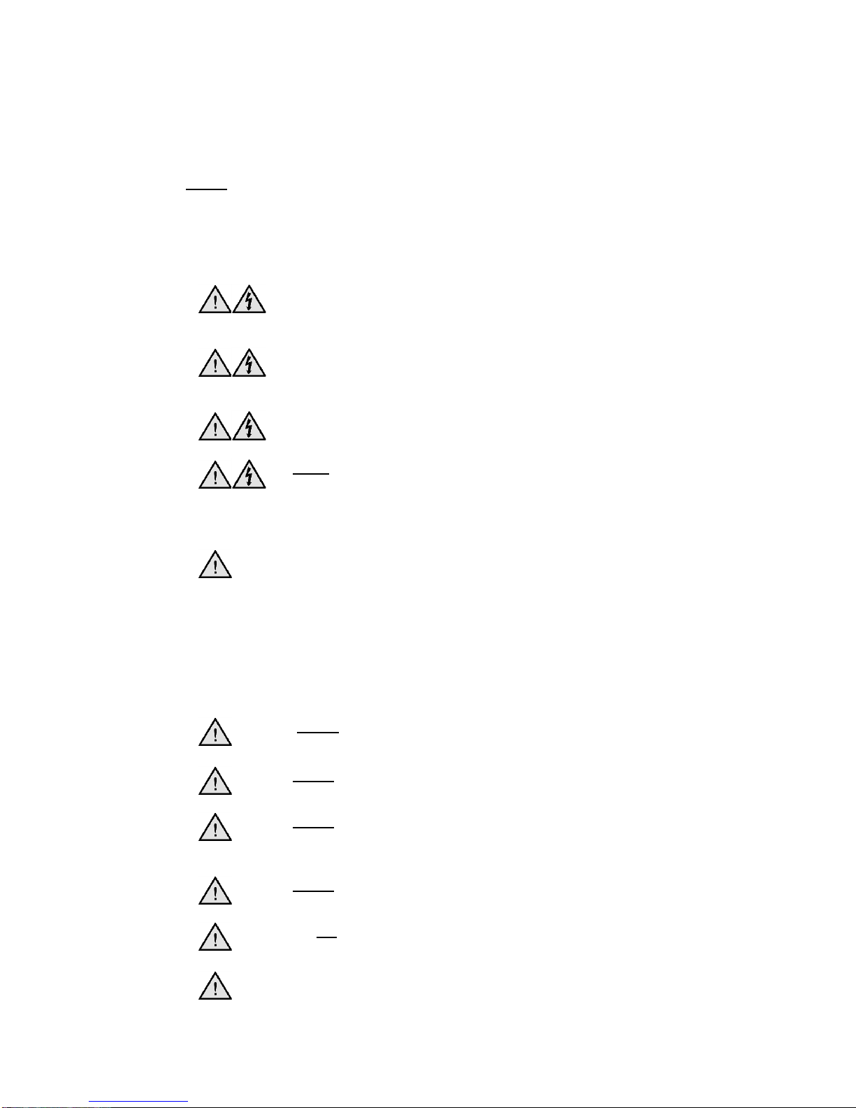
2.2. Symbols defined.
Caution, risk of danger. See note or adjacent
symbol.
Protective conductor terminal to be earthed.
(Do not loosen or disconnect).
Caution / risk of electric shock
Recyclable Packing Material
Do not dispose of product in normal domestic
waste.
Caution. Hot surface.
Refer to Instruction book
Bio Chemical Hazard. Caution required. Will
require decontamination.
Page 5 of 20 M6627 Issue 7.0
3. SAFETY INFORMATION.
This product has been designed for safe operation when used as detailed in accordance with
the Manufacture’s instructions.
NOTE: Failure to use this equipment in accordance with the manufacture’s operating instruction
may compromise your basic safety protection afforded by the equipment and may invalidate the
warranty / guarantee. The warranty / guarantee does not cover damaged caused by faulty
installation or misuse of the equipment.
3.1. Prevention of Fire and Electric Shock.
To prevent a risk of fire or electric shock, DO NOT open your
product case without authorisation. Only qualified Service
personnel should attempt to repair this product
Replace fuses only with the type as listed in section, Parts and
Accessories and Technical Specifications. (See fuse type and
rating)
Ensure the Mains Power Supply conforms to rating found on the
data plate located on the back of this Product.
Never Operate this equipment with out connection to earth /
ground. Ensure the mains supply voltage is correctly earthed /
grounded in accordance with current area legislation.
3.2. General Safe Operating Practice.
Always follow good laboratory practice when using this
equipment. Give due recognition to your company’s safety and
legislative health & safety procedures and all associated
legislation applicable to your areas of operation. Check
laboratory procedures for substances being heated and ensure
all hazards (e.g. explosion, implosion or the release of toxic or
flammable gases) that might arise have been suitably
addressed before proceeding. When heating certain
substances the liberation of hazardous gases may require the
use of a fume cupboard or other means of extraction.
Do not position the product so that it is difficult to disconnect
from the mains supply.
Do not immerse unit in water or fluids.
Do not spill substances onto this unit. If spillage does occur,
disconnect unit from mains supply and follow instructionas
detailed in Section ‘Maintenance’.
Do not cover this unit whilst in use.
It is not recommended to leave any heating apparatus
unattended during operation.
Only use Original Equipment manufacture’s spares and
accessories. Ref Section 10.

Page 6 of 20 M6627 Issue 7.0
The equipment is not spark, flame or explosion proof and has
not been designed for use in hazardous areas in terms of BSEN
60079-14:1997. Keep flammable, low flash point substances
away from the apparatus.
Do not operate or handle any part of this product with wet
hands.
Do not touch the heating surface whilst in use.
Do not lean or stretch over equipment.
Keep the Mains Plug and Lead set cable away from the heating
surface.
Page 7 of 20 M6627 Issue 7.0
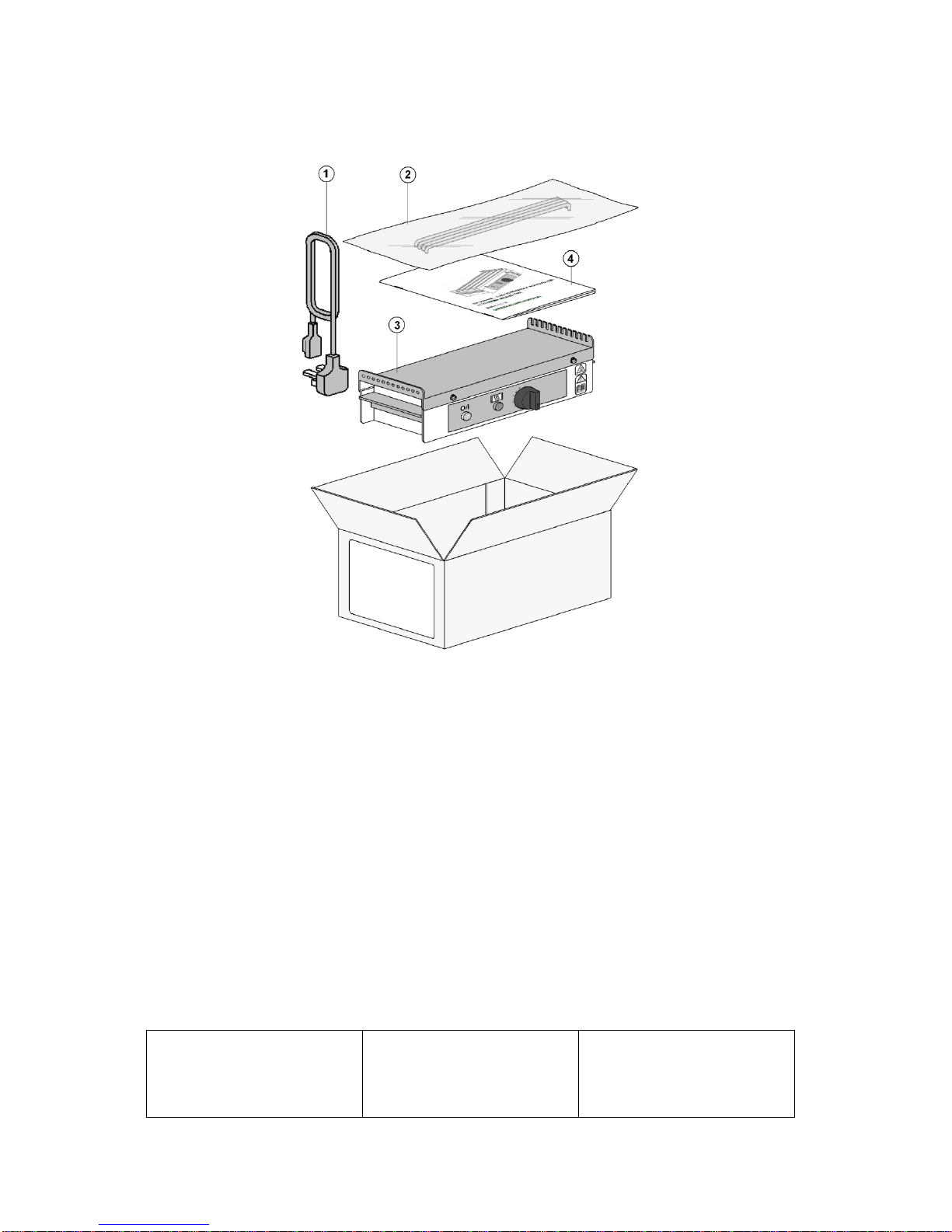
4. UNPACKING AND CONTENTS.
Please check the contents of this carton against the diagram.
For your future reference
please record your products
Serial and Model numbers.
Unit Serial Number
Unit Model/Cat Number.

Page 8 of 20 M6627 Issue 7.0
5. INSTALLATION.
5.1. Electrical safety and installation.
5.1.1. This equipment is designed to safe under the following conditions:-
Indoor use.
Altitude up to 2000 meters.
Temperatures between 5C and 40C.
Maximum relative humidity 80% for temperatures up to 31C decreasing linearly to 50%
relative humidity at 40C.
Mains supply voltage fluctuations up to 10% of the nominal voltage.
Transient over voltages typically present on the mains supply.
Applicable rated pollution degree 2.
5.1.2. This equipment must be earthed / grounded to a fixed earth / grounded mains
socket outlet. The mains supply is to be earthed / grounded in accordance with current
legislation.
5.1.3. Ensure only the correct rated mains input fuses are fitted. (Where applicable ensure the
correct mains cable fuse if fitted). See Technical Information Section 8 of the Instruction
book.
5.1.4. Check the voltage on the product data label of this unit. Ensure the rating conforms to
your local supply.
5.1.5. It is recommended this unit be connected to a mains supply source which incorporates
an RCD or GFCI device.
5.1.6. The unit is supplied with a moulded plug and mains lead set wired as follows.
Green / Yellow
or
Green
=
Earth / Ground
Blue
or
White
=
Neutral
Brown
or
Black
=
Live / line hot.
5.2. Install equipment is used on a clean, dry, non-combustible, solid work surface with at
least 300mm suitable clearance all around from other equipment / objects.

Page 9 of 20 M6627 Issue 7.0
6. ENVIRONMENTAL PROTECTION.
6.1. Electrothermal has given due consideration to environmental issues within the
design and manufacturing process without compromising end product
performance and value.
6.2. Packaging materials have been selected such that they may be sorted for
recycling.
6.3. At the end of your product and accessories life, it must not be discarded as
domestic waste. Ref: EU Directive 2002/96/EC on Waste Electrical and Electronic
Equipment Directive (WEEE). Please contact your distributor / supplier for further
information. For end users outside of the EU consult applicable regulations.
6.4. This product should only be dismantled for recycling by an authorised recycling
company.
This product and accessories must be accompanied by a completed
Decontamination Certificate prior to any disposal. Copies of the Certificate are available
from your distributor of Electrothermal products, or you may copy and enlarge from
‘Appendix A’ of the instruction book.
Electrothermal is registered as Electrothermal Engineering Limited with the Environment Agency as a producer of
WEEE through an authorised compliance scheme.

Page 10 of 20 M6627 Issue 7.0
7. PRODUCT OPERATION
This unit has been designed for safe operation when used as described in
accordance with the manufactures instructions.
Note: failure to use this equipment in accordance with the manufactures ‘Instruction book’ may
compromise your basic safety protection afforded by this equipment and may invalidate the
terms of the Warranty / Guarantee.
7.1. Overview.
Your Slide Drying Bench has been designed for easy operation. The illustrations
show a detailed layout of your Slide Drying Bench.
Item No
Description
1
Support Bars
2
Drying surface
3
Hot surface warning
4
Earth test point
5
Carrying handles
6
Power On indicator
7
Heater On indicator
8
Temperature control regulator knob and On/Off switch.
9
Mains input IEC socket.
10
Data plate label.
7.2. Place the slides to be dried on the bench surface. The slides can be arranged on
the bench in a number of ways as illustrated.
7.3. Connect the unit to the mains power ensuring the correct voltage is being applied.
The White ‘Power on’ Neon will illuminate.
7.4. Set the temperature control regulator knob to position 10. The Amber ‘Heater on’
neon will illuminate.
7.5. When the required bench temperature has been reached (this can be monitored
using a suitable Surface temperature Probe) turn the regulator down to just
maintain required temperature setting.
The maximum temperature obtainable at setting 10 is 100C nominal.
7.6. When slides are dry, switch off the unit at the regulator knob and disconnect from
the mains electrical supply. Allow slides to cool before further handling.
Page 11 of 20 M6627 Issue 7.0
8. TECHNICAL SPECIFICATION.
8.1. Specification.
Maximum power consumption.
150 Watts
Fuse rating (115V).
2.5 Amps (5 x 20mm dia Glass
Quickblow)
Fuse rating (230V).
1.25 Amps (5 x 20mm dia Glass
Quickblow)
Operational climatic conditions.
Temperature range 5C to 40C.
Humidity not to exceed 80%.
Heating Element
Silicone Rubber Mat Heater.
Case Construction
Painted Aluminium.
Thermal Insulation
Ceramic Fibre sheet.
Capacity.
Maximum 50 slides at 76 x 25mm
(3” x 1”).
Mains Supply Power.
230V-AC or 115/100V-AC @
50/60Hz
Mains Power Lead set (UK) 13A BS1362
3 core earthed / ground. 2 meters
long
Moulded IEC plug and Lead set –
supply cord H05 V V-F- Replace
only with equivalent cable.
Mains Power Lead set (Europe)
3 core earthed / ground. 2 meters
long
Moulded IEC plug and Lead set –
supply cord H05 V V-F- Replace
only with equivalent cable.
Mains Power Lead set (USA)
3 core earthed / ground. 2 meters
long
Moulded IEC plug and Lead set –
supply cord SJT VW 1- Replace
only with equivalent cable.
Lead set plug fuse (UK –only)
13A
8.2. The Ingress Protection rating for this product is classified as IPX1
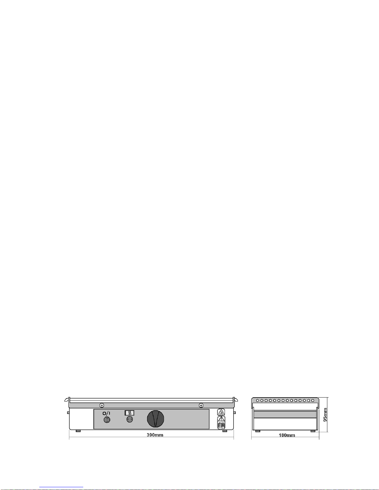
8.3. Dimensions & Weight (unpacked).
Weight 1.8 Kg (4lb).

Page 12 of 20 M6627 Issue 7.0
9. MAINTENANCE
9.1. General Information
Unplug the unit from the mains input voltage supply and allow it to cool before
undertaking any maintenance tasks.
Maintenance should only be carried out under the direction of the Responsible Body, by a
competent electrician. Failure to do so may result in damage to the product and in extreme
cases be a danger to the end user.
With proper care in operation this equipment has been designed to give many years of reliable
service. Contamination or general misuse will reduce the effective life of this product and may
cause a hazard.
Maintenance for the unit should include:
Periodic electrical safety testing (an annual test is recommended as the minimum
requirement).
Regular inspection for damage with particular attention to the mains lead and plug set.
Routine cleaning of the equipment should be undertaken using a clean cloth.
DO NOT USE SOLVENTS FOR CLEANING ANY PART OF THIS EQUIPMENT.
9.2. Fuse Replacement.
The mains fuse holder is located at rear your product. Refer to Technical Specification, ‘Fuse
Rating’ for correct fuse type and rating. Turn your product off and remove it from the mains
supply. Open fuse draw and remove fuses. Fit replacement fuses and close the draw.
9.3. Replacing the Heater Mat.
WARNING: The Insulation Pressure Plate contains insulation made from Refractory Ceramic
Fibres (RCF) classified as a category 2 carcinogen under EU Directive 67/548/EC. Follow the
guidelines for working with RCF as laid down in the ECFIA Code of Practise.
In the event of a heater element becoming open circuit the following procedure
should be adopted for its replacement.
9.3.1. Unplug and disconnect the unit from the power source.

Page 13 of 20 M6627 Issue 7.0
9.3.2. Unscrew and remove the screws retaining the top plate. Lift the top plate
clear.
9.3.3. Hinge back the heater mat and insulation pressure plate, the insulation
should be carefully removed and placed on the top plate. This will reduce the
risk of damage to the insulation.
9.3.4. Remove any wire ties, now disconnect the heater leads from the amber
neon.
9.3.5. Connect the replacement mat.
9.3.6. Replace wire ties and insulation and hinge the heater into position over the
insulation.
9.3.7. Place Top plate in position and refit all the fixing screws.
9.3.8. The Responsible Body shall check the electrical safety of the unit before
further use.

Page 14 of 20 M6627 Issue 7.0
9.4. Spillage and Decontamination.
In the event of spillage switch off and unplug this product from the mains electrical supply. Wipe
off all excess liquid from the reaction block and surrounding area using an absorbent soft cloth.
Allow sufficient time for any ingressed liquid to evaporate before commencing with use.
If in doubt please consult Customer Support. Refer to section 10.
If the equipment has been exposed to contamination, the Responsible Body is
responsible for carrying out appropriate decontamination. If hazardous material has
been spilt on or inside the equipment, decontamination should only be undertaken
under the control of the Responsible Body with due recognition of possible hazards.
Before using any cleaning or decontamination method, the Responsible Body should
check with the manufacturer the proposed method will not damage the equipment.
Prior to further use, the Responsible Body shall check the electrical safety of the unit.
Only if all safety requirements are met can the unit be used again. The above procedure
is intended as a guide. Should spillage occur with a toxic or hazardous fluid then special
precautions may be necessary.
Decontamination Certificate.
Note: In the event of this equipment or any part of the unit becoming damaged, or requiring
service, the item(s) should be returned to the manufacturer for repair accompanied by a
decontamination certificate. Copies of the Certificate are available from
Distributor/Manufacturer. Appendix A of this instructions book may be copied and
enlarged.
At the end of life, this product must be accompanied by a Decontamination Certificate.
See section 6.3 and 6.4

Page 15 of 20 M6627 Issue 7.0
10. PARTS & ACCESSORIES.
230V
115V
Heater Mat
AZ9136
AZ9137
Insulating Pressure Plate
AZ9138
AZ9138
Slide Support Rod Qty 4
AZ9139
AZ9139
Rubber Feet Qty 4
AZ9140
AZ9140
Neon Clear
AZ9141
AZ9142
Neon Amber
AZ9143
AZ9144
Handles Qty 2
AZ9145
AZ9145
Energy Regulator
AZ9127
AZ9128
Control Knob
AZ9133
AZ9133
Fuse
AZ9039 (F1.25A)
AZ9040
(F2.5A)
Plug and lead set (UK)
M6902
-
Plug and lead set (Europe)
M6332
-
Plug and lead set (USA)
-
M6288

Page 16 of 20 M6627 Issue 7.0
APPENDIX ‘A’. DECONTAMINATION CERTIFICATE.
Electrothermal. Electrothermal House. Unit12A, Purdeys Way. Purdeys Industrial Estate. Rochford. Essex. SS4
1ND. Great Britain
DECONTAMINATION CLEARANCE CERTIFICATE
For the Inspection, Repair or Return of Medical, Laboratory or Industrial Equipment.
Prior to a Service Engineer working on equipment that has been in an environment where substances hazardous to health
may have been used, you are requested to provide the following information:
CUSTOMER DETAILS
Company:-
Address:-
Department:-
Contact Name:-
Tel No:-
Fax No:-
Post Code:-
Product Description
Model No:-
Serial No:-
Has the equipment been exposed to any of the following, Please answer all questions by deleting YES/NO as applicable and byproviding
details in section 2 below.
A. Blood, body fluids, Pathological
specimens
YES/NO
Provide details if YES
B. Biodegradable material that could
become a hazard
YES/NO
Provide details if YES
C. Other biohazard
YES/NO
Provide details if YES
D. Chemical or substances hazardous to
health
YES/NO
Provide details if YES
E. Radioactive substances State name(s)
and quantities of isotopes and checks
made for residual activity
YES/NO
Provide details if YES
F. Other hazards
YES/NO
Provide details if YES
2. Please provide details of any hazard present as indicated above. Include details of names and quantities of
agents as appropriate:-
3. Your method of decontamination (please describe):-
4. Are there likely to be any areas of residual contamination (please specify)
I declare that the above information is true and complete to the best of my knowledge and
belief.
Authorised signature:-
Name (please print):-
Title/Position:-
For and behalf of:-
Date:-

Page 17 of 20 M6627 Issue 7.0
11. CUSTOMER SUPPORT.
For help and support in using this product, please contact at the following address.
Electrothermal.
Electrothermal House.
Unit12A, Purdeys Way.
Purdeys Industrial Estate.
Rochford,
Essex. SS4 1ND
Great Britain.
Tel +44(0)1702 303350
Fax+44(0)1702 468731
E-Mail: info@electrothermal.com

Page 18 of 20 M6627 Issue 7.0
12. NOTES

Page 19 of 20 M6627 Issue 7.0

Page 20 of 20 M6627 Issue 7.0
13. EC DECLARATION OF CONFORMITY.
CE marked products and associated accessories covered by this Instruction book conform to the
essential requirements of the following directives:
EMC Directive.
Low Voltage Directive.
A full copy of the EC Declaration / Conformity document can be obtained from the manufacture at the
email address info@electrothermal.com
Electrothermal.
Electrothermal House.
Unit12A, Purdeys Way.
Purdeys Industrial Estate.
Rochford,
Essex. SS4 1ND
Great Britain.
Tel +44(0)1702 303350
Fax+44(0)1702 468731
Email: info@electrothermal.com
Http www.electrothermal.com
For the America’s and Canada, contact:
Techne Incorporated, 3 Terri Lane,
Suite 10 Burlington, NJ 08016 USA.
Toll free:800-225-9243Tel: 609-589-2560
Fax: 609-589-2571
Email: [email protected]
Http www.techneusa.com
2011 Electrothermal. All rights reserved.
Printed in Great Britain
This manual suits for next models
2
Table of contents


