ELK Golf GT LITHIUM V1 Instruction manual

GTLITHIUMV1Workshopmanual 1
©2013ElkingtonGolfPtyLtd
GTLITHIUMV1
Workshopmanual
ForApprovedE•L•KGolfServiceCentres

GTLITHIUMV1Workshopmanual 2
©2013ElkingtonGolfPtyLtd
GTLITHIUMV1Workshopmanual
TABLEOFCONTENTS
1/REMOVINGTHETOPHANDLE………………………………………………………………….Page3
2/REPLACINGTHESPEEDCONTROLSWITCH……………………………………………….Page3–11
3/REPLACINGTHEPCBBOARD/DISPLAYINTHETOPHANDLE……………………Page11
4/REFITTINGTHETOPHANDLE……………………………………………………………………Page12
5/REPLACINGOFTHEMOTORCONTROLLER……………………………………………….Page13–16
6/REPLACINGTHEMOTOR…………………………………………………………………………..Page16–18
7/REPLACINGTHEAXLEDRIVEPINS…………………………………………………………….Page19
8/REPLACINGTHESTEMCABLE……………………………………………………………………Page20–26
9/REPLACINGTHEAXLEBEARINGS……………………………………………………………….Page26–28
10/REPLACING/REMOVALOFTHEBATTERYTRAY……………………………………….Page28–29
11/REPLACING/REMOVALOFTHEDRIVEAXLE……………………………………………Page29–33
12/REPLACINGTHEGEARBOX……………………………………………………………………….Page33–35
13/REPLACINGTHEUPPERBAGSUPPORT…………………………………………………….Page36–37
14/REPLACINGTHELOWERBAGSUPPORT……………………………………………………Page37–38
15/REPLACINGTHEFRONTWHEEL&HOUSINGASSEMBLY…………………………..Page39
16/ADJUSTINGFRONTWHEELTRACKING………………………………………………………Page39–40
GTLITHIUMV1Workshopmanual 3
©2013ElkingtonGolfPtyLtd
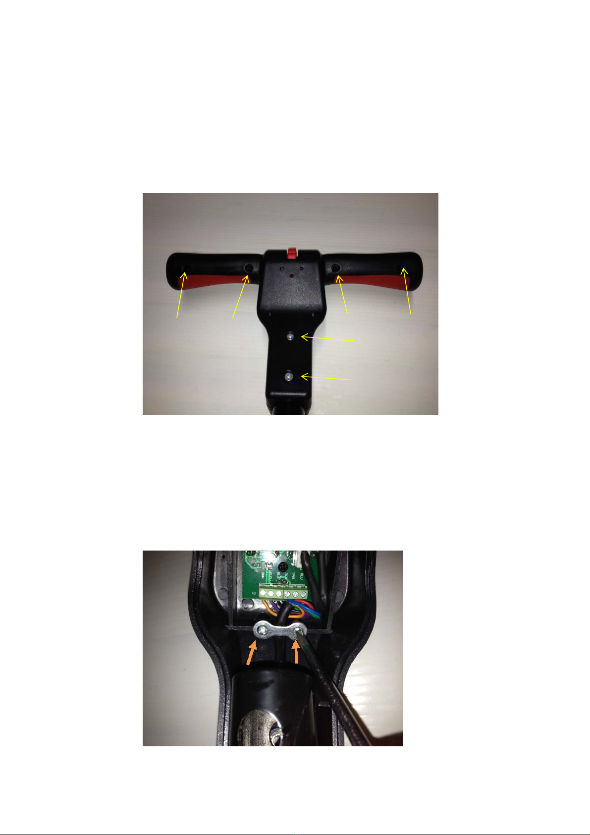
1/REMOVINGTHETOPHANDLEASSEMBLY
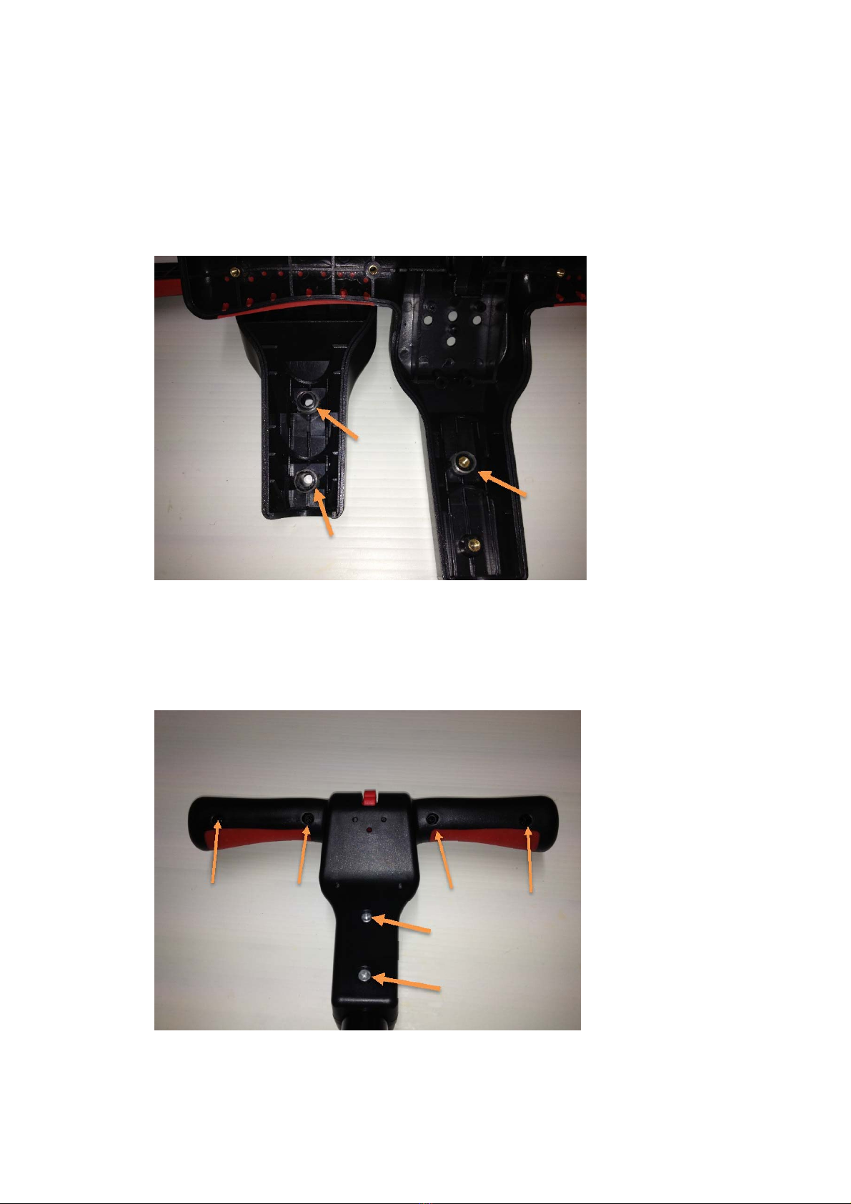
Thereare6screwswhichsecuretheTopHandleassemblytotheMainFrameUpperTubeasshown
bythearrowsinfigure‐No1PLEASENOTE–Thereare3sleeves/busheswhichsitbetweenboth
sectionsofthehandleandUppermainframetube.Ensuretheyareinplacebeforerefittingthe
handle.RefertoFigureNo15A.
FigureNo1
2/REPLACINGTHESPEEDCONTROLSWITCH
Withthetophandleassemblyremovedfromthemaintube,itwillnowseparateintotwohalves.
WhilesupportingtheuppersectionoftheTopHandleAssemblyastoavoiddamagingthestem
cablewiring,removethetwoPhillipsscrewsindicatedbyarrows,securingthecablesupportbracket
aspicturedinFigureNo2.
FigureNo2
GTLITHIUMV1Workshopmanual 4
©2013ElkingtonGolfPtyLtd
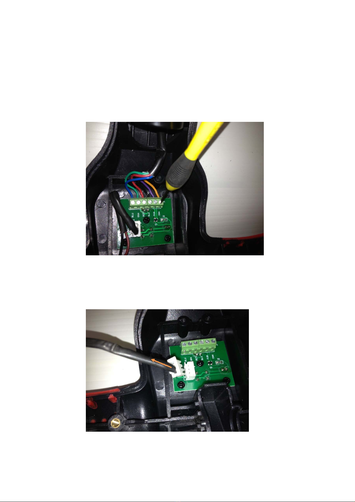
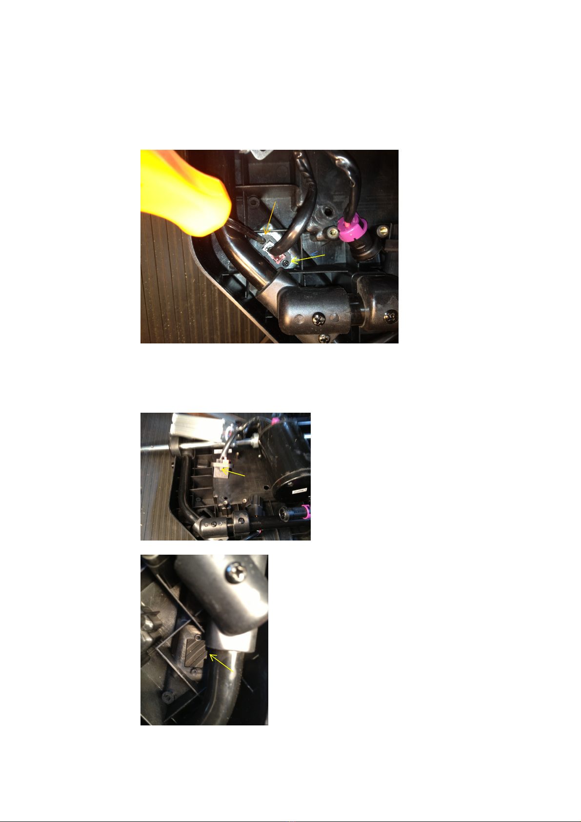
LoosenthescrewswhichsecuretheStemCableWiringtotheTerminalBlockandremovetheStem
CableWiringfromtheTerminalBlockaspicturedinFigureNo3.
PLEASENOTE–TheStemCableWiringiscolourcodedandthecolourofeachwiremustcorrespond
withthecoloursprintedontheTerminalBlockaspicturedinFigureNo3.
FigureNo3
Unplug/DisconnecttheSpeedSwitchWiring,fromthePCBBoardaspicturedinFigureNo4.
FigureNo4

GTLITHIUMV1Workshopmanual 5
©2013ElkingtonGolfPtyLtd
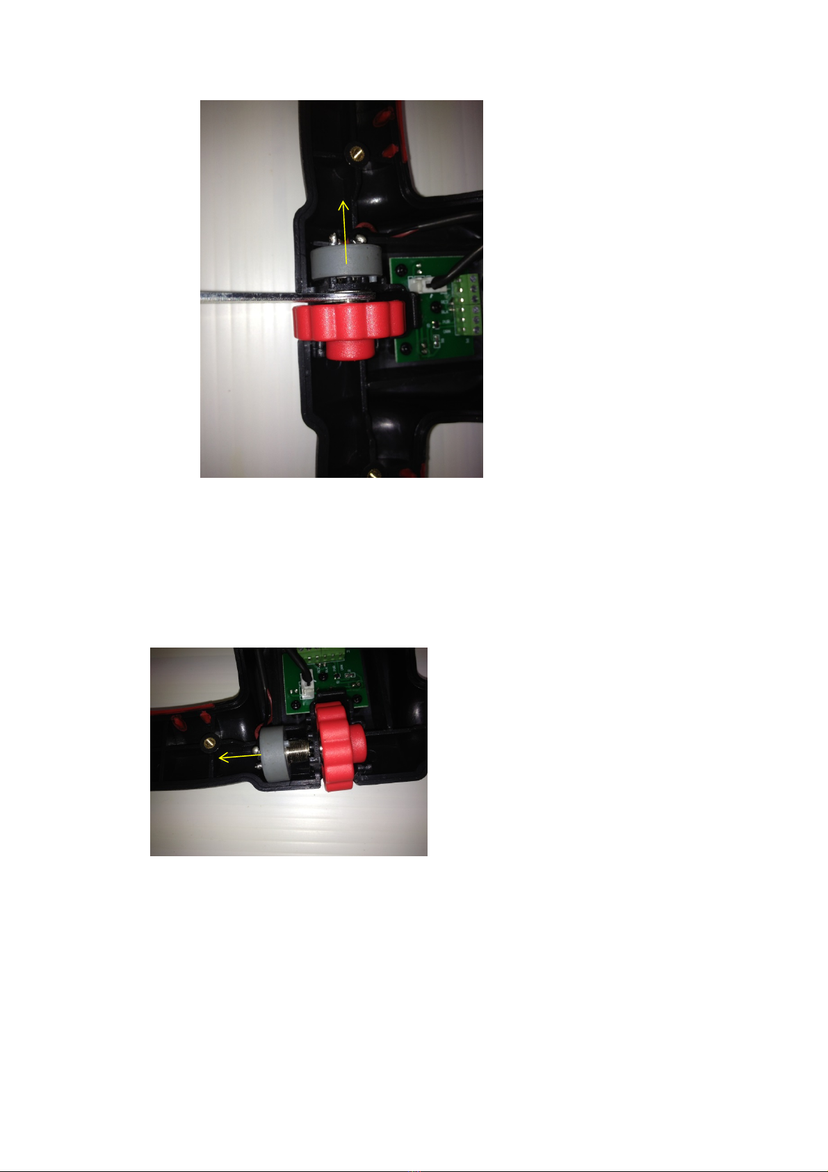
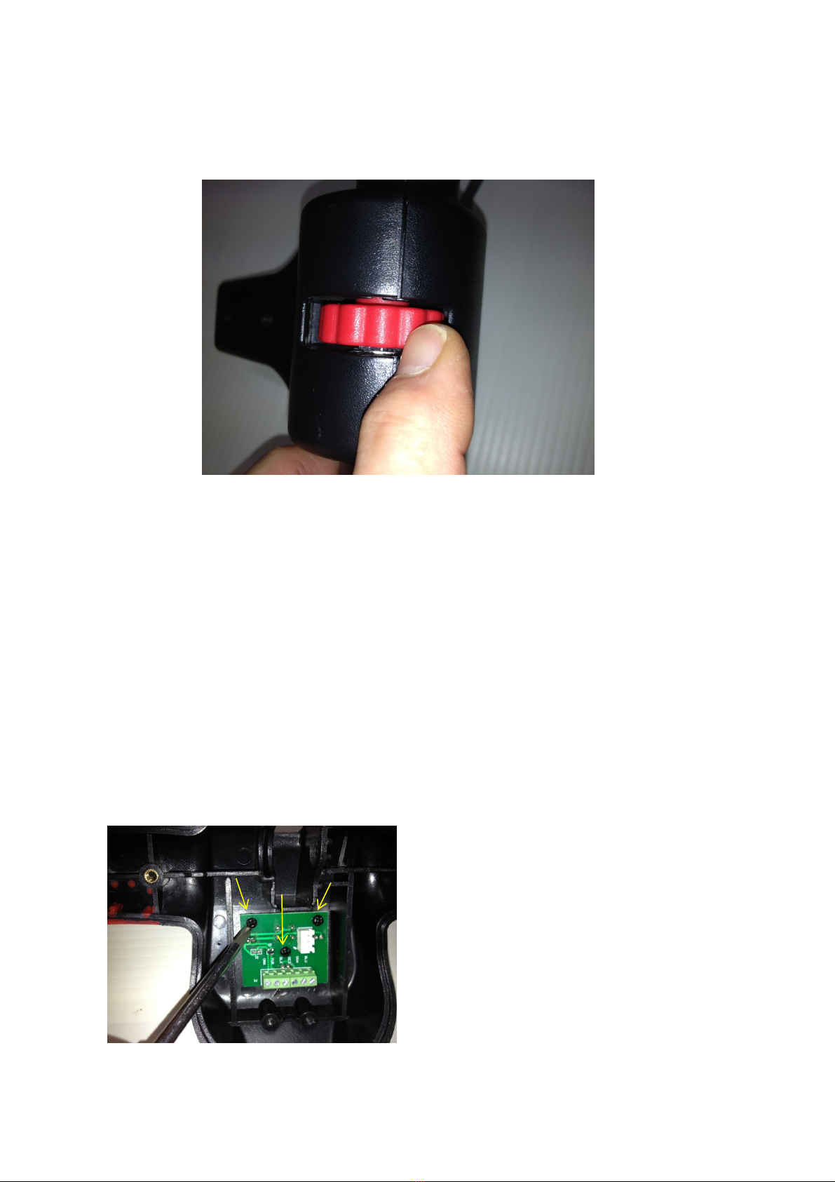
BeforeyoucanloosentheretainingnutwhichsecurestheSpeedSwitchtotheUpperHandle,you
mustfirstslidetheRedSpeedDialasfaraspossibletotheright,whichwillallowyoutoaccesstothe
securingnut.Tocarryoutthisprocess‐placeascrewdriverinthepositionaspicturedinFigureNo5
andgentlyshiftthespeeddialinthedirectionofthearrowsshown,asfarasyoucantotherightby
rotatingthescrewdriver.
PLEASENOTE–Beextremelycarefulwhilecarryingoutthispartoftheprocedure,astoavoid
damagingtheTopHandleAssembly.
FigureNo5
OnceyouhavecarriedouttheprocedureaspicturedinFigureNo5,youwillbeabletoseeandhave
accesstotheSpeedSwitchsecuringnut,aspicturedinFigureNo6andindicatedbythearrow.

GTLITHIUMV1Workshopmanual 6
©2013ElkingtonGolfPtyLtd
FigureNo6
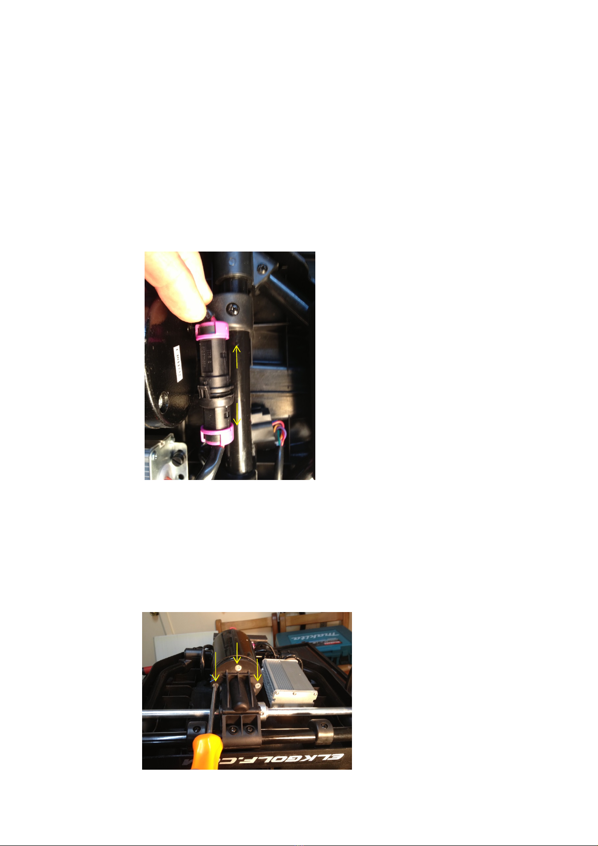
LoosentheSpeedSwitchsecuringnutbyusingthespeciallysuppliedSpannerwhichwassuppliedto
you,withyourServiceCentreStartUpKitaspicturedinFigureNo7.
PLEASENOTE–Whilelooseningthesecuringnut,youwillneedtoslidetheSpeedSwitchinthe
directionofthearrowinFigureNo7&7Aatthesametime,whichwillallowcompleteremovalof
theSpeedSwitch.
GTLITHIUMV1Workshopmanual 7
©2013ElkingtonGolfPtyLtd
FigureNo7
OncetheSpeedSwitchsecuringnuthasbeencompletelyloosened,keepslidingtheSpeedSwitch,in
thedirectionofthearrowaspicturedinFigureNo7A,untilitiscompletelyfreefromtheTopHandle
AssemblyaspicturedinFigureNo8
FigureNo7A

GTLITHIUMV1Workshopmanual 8
©2013ElkingtonGolfPtyLtd
FigureNo8
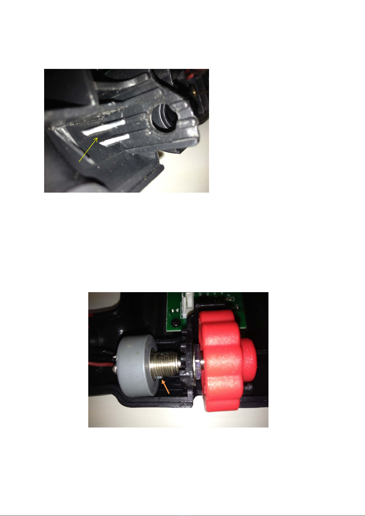
BeforebeginningtofitthenewSpeedSwitch,itisimportanttonote‐ThattheshaftontheSpeed
Switch,hasa“flat”sectiontoallowtheSpeedDialtolocateontheshaftandalocating“lug”onthe
housingoftheswitchaspicturedinFigureNo9.Thelocating“lug”ontheswitchneedstobe
positionedcorrectlyintotheTopHandleAssemblyaspicturedanddefinedinthesectionoftheTop
HandleassemblyasindicatedbythearrowonFigureNo10.TofitthenewSpeedSwitch,beginby
slidingtheSpeedSwitchthroughthemountingholeintheTopHandleAssemblyandplacingthe
washerandnutontotheshaftaspicturedinFigureNo9.
FigureNo9
GTLITHIUMV1Workshopmanual 9
©2013ElkingtonGolfPtyLtd
FigureNo10belowshowsthepositionthatthelocating“lug”ontheSpeedSwitchmustlocateinto
ontheTopHandleassemblydefinedbyanarrow.
FigureNo10
OncetheSpeedSwitchisplacedintothetophandleaspreviouslyshowninFigureNo9,theSpeed
DialmustbeplacedontotheshaftoftheSpeedSwitch,aligningtheflatsectionontheSpeedSwitch
shaftwiththeflatsectionontheSpeedDialandthelocatingluginthecorrectpositionaspicturedin
FigureNo11.
FigureNo11
.

GTLITHIUMV1Workshopmanual 10
©2013ElkingtonGolfPtyLtd
BeforeyoucantightenthesecuringnutontheSpeedSwitch,youwillhavetostartthenutonthe
threadoftheSpeedSwitchbyusingasmallscrewdrivertoturnthenutaspicturedinFigureNo12.
Thispartoftheprocesscanbealittletrickyandrequiresasteadyhandandalittlepatience.Be
verycarefulnottotryandforcethenutonwithaspannerandcrossthreadthenut.
PLEASENOTE–ItisextremelyimportanttoensuretheLocatingLugontheSpeedSwitchislocated
correctlyintotheslotontheTopHandleassembly.
FigureNo12
OnceyouaresurethatthenuthasstartedcorrectlyonthethreadoftheSpeedSwitch,youarenow
abletotightenthesecuringnutwiththespecialspannerprovidedaspicturedinFigureNo13.Once
thenutistight,youwillneedtopushtheSpeedDialfurtherontotheshaftuntilitiscorrectly
centredintotheopeningoftheTopHandleassembly.
FigureNo13
GTLITHIUMV1Workshopmanual 11
©2013ElkingtonGolfPtyLtd
BeforeyourefittheTopHandleassemblybackontothebuggy,itisadvisabletoplacethetwohalves
ofthehandletogetherandensurethattheSpeedDialinnotbindingontheTopHandleassembleas
picturedinFigureNo14
FigureNo14
OnceyouarecertainthattheSpeedDialisturningcorrectlywithoutinterference,thenreconnect
theSpeedSwitchwiringtothePCBboardandreconnectthestemcablewiring,ensuringthateach
colouredwirecorrespondswiththecolourprintedontheterminalblock.FittheStemCablesecuring
bracketandrefitthehandletothebuggybyreferringtoparagraphNo4.Testtheoperationofthe
speedswitchandensurethatitisfunctioningcorrectlyandtheSpeedDialisnotfoulingontheTop
Handleassembly.
3/REPLACINGTHEPCBBOARD/DISPLAYINTHETOPHANDLE
Tocarryoutthisprocess,followthestepsasperFigures1to4thenremovethe3screwsindicated
byarrows,whichsecurethePCBboardasperFigureNo15andreplacethePCBboard.
Tocompletethisprocedure,reversethestepsofFigures1to4andtestthatthePCBboardis
operatingcorrectlyandallthreedistancesettingsarefunctioningcorrectlyalso.
FigureNo15
GTLITHIUMV1Workshopmanual 12
©2013ElkingtonGolfPtyLtd
4/REFITTINGTHETOPHANDLE
Beforerefittingthetophandle,pleaseensurethatthe3bushes/sleevesareinplace(onsome
modelsonly,asindicatedbyarrowsonFigureNo15A
Pleasebecarefulnottodropthesebushesintothemainupperframetubewhenrefittingthe
handle.
FigureNo15A
RefitandtightenthescrewsasindicatedbyarrowsonfigureNo15B
FigureNo15B
GTLITHIUMV1Workshopmanual 13
©2013ElkingtonGolfPtyLtd
5/REPLACINGOFTHEMOTORCONTROLLER
ToreplacetheMotorController,firstlyturnthebuggyupsidedown.
AftermanyyearsofextensiveresearchintofailedMotorControllers,itwasdiscoveredthatoneof
themaincausesforfailureisrepeatedshock.Forthisreason,theGTLithiumMotorControlleris
rubbermountedandtherubbermountingsthatarepositionedonthemountingscrewsofthe
MotorController,MUSTbeputbackinplacewhenreplacingtheunit.
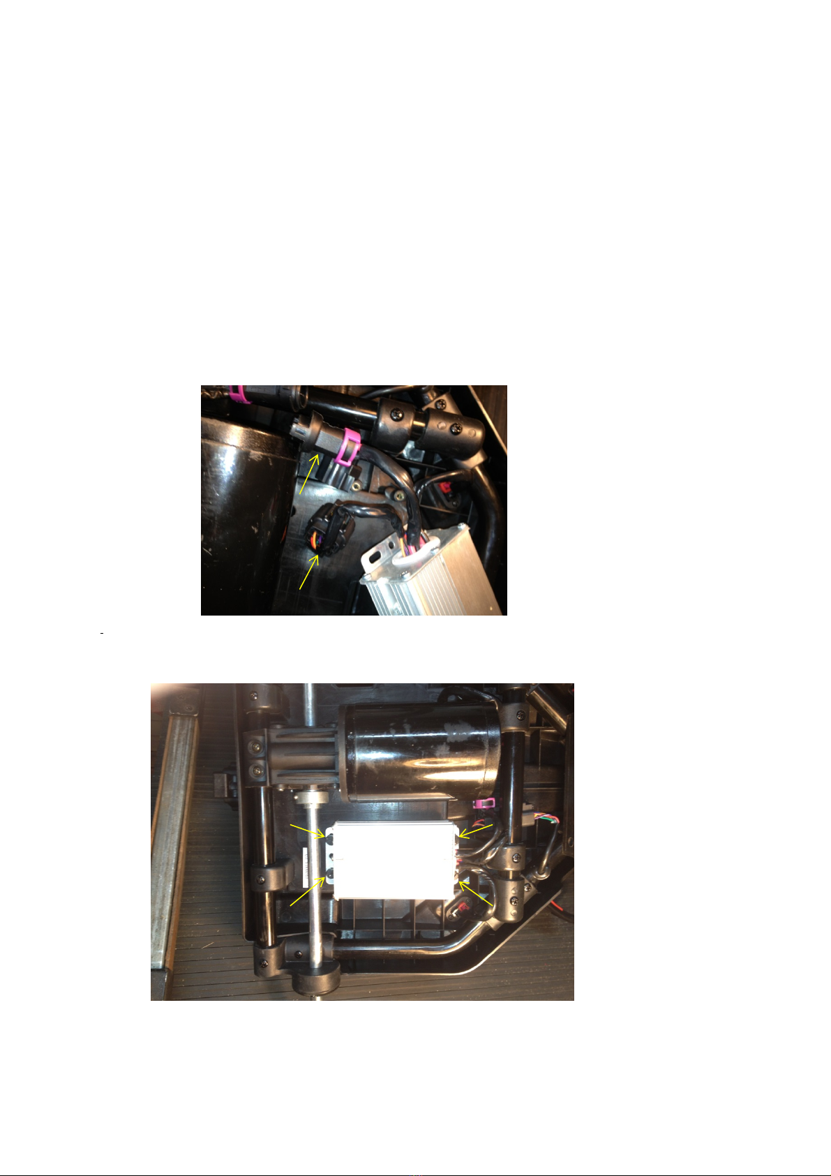
ToremovethemotorController,firstlyyoumustremovethecableties,securingthewiringtothe
undersideoftheBatteryTrayanddisconnectthewiringfromtheMotorandStemCableindicatedby
arrowsaspicturedonFigureNo16Below.
Fffffffff
Loosenthe4screwsthatsecuretheMotorControllerasindicatedinFigureNo17
FigureNo17
GTLITHIUMV1Workshopmanual 14
©2013ElkingtonGolfPtyLtd
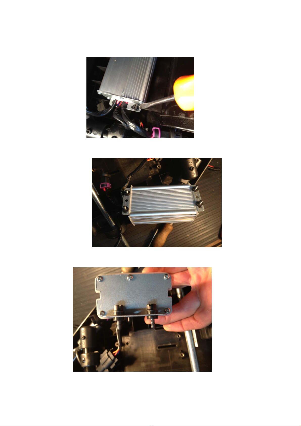
LoosenScrewsenoughtofreeMotorControllerformthebatterytray,butdonotremovethescrews
completelyastherubberbusheswillfallofftheretainingscrews.RefertoFiguresNo18,19&20
FigureNo18
FigureNo19
FigureNo20
GTLITHIUMV1Workshopmanual 15
©2013ElkingtonGolfPtyLtd
NowdiconnecttheBatteryconnectionwiringwhichhousesthe2AndersonConnectors,byremoving
the2retaingscrews,indicatedbyarrowsonFigureno21.
TheMotorControllerisnowfreetoberemoved.Makesurethatyoudonotlooseanyrubber
bushesintheprocess.
FigureNo21
TofitthenewMotorController,startbyrefitingtheBatteryConnectionwiring.Pleaseensurethat
locatinglugonthehousingofthisplugcorrespondswiththecutoutintheBatteryTrayasindicated
byarrowsonFiguresNo22&23.
FigureNo22
FigureNo23
GTLITHIUMV1Workshopmanual 16
©2013ElkingtonGolfPtyLtd
Fitthe2screwswhichsecurethisplugandensurethatthesescrewsarenotovertigtened,causing
damagetotheBatteryTray.
Pleaseensurethattherubberbushesareplacedon4screwsasperFigureNo20,beforeattempting
torefittheControllerandmakesurethatall4screwsarestartedcorrectlyandnotcrossthreaded
beforetighteningcompletely.Onceall4srewsaretight,reconnecttheStemCableWiringand
Motorwiring,thenfit3newcabletiesandsecurethewiring.
6/REPLACINGTHEMOTOR.
BeginbyremovingthecabletiessecuringtheMotorwiringtotheframe,thenunplugingtheMotor
Wiring,fromtheMotorControlleraspicturedinFigureNo24
FigureNo24
Removethe3ScrewswhichsecuretheMotortotheGearBoxasindicatedbyarrows
onFigureNo25
FigureNo25
GTLITHIUMV1Workshopmanual 17
©2013ElkingtonGolfPtyLtd
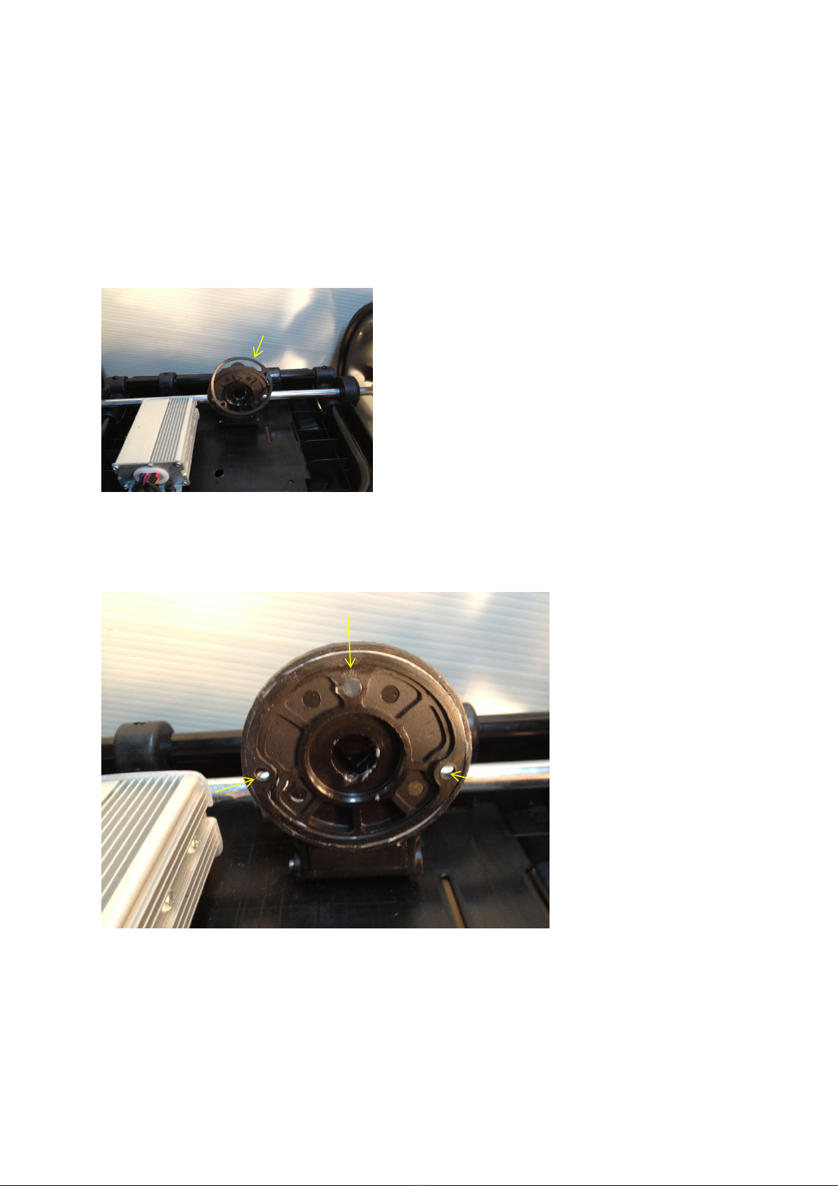
TheMotorcannowbeseperatedfromtheGearbox.Becarefulnottoloosetherubbersealthatsits
betweentheMotorandtheGearboxaspicturedinFigureNo26.Beawarethatthissealmaystay
stucktotheMotorwhentheMotorisremoved.
FigureNo26
BeforefittingthenewMotor,ensurethatthesealiscorrectlypositionedontheflangeofthe
Gearbox.Itisadviseabletouse,eithersiliconeorgreasetohelpkeepthissealinplacepriorto
fittingthenewMotorasperFigureNo27.
FigureNo27
Ensurethatthe3holesintherubberseal,lineupwihthe3holesintheGearboxflangeasindicated
byarrowsinFigureNo27
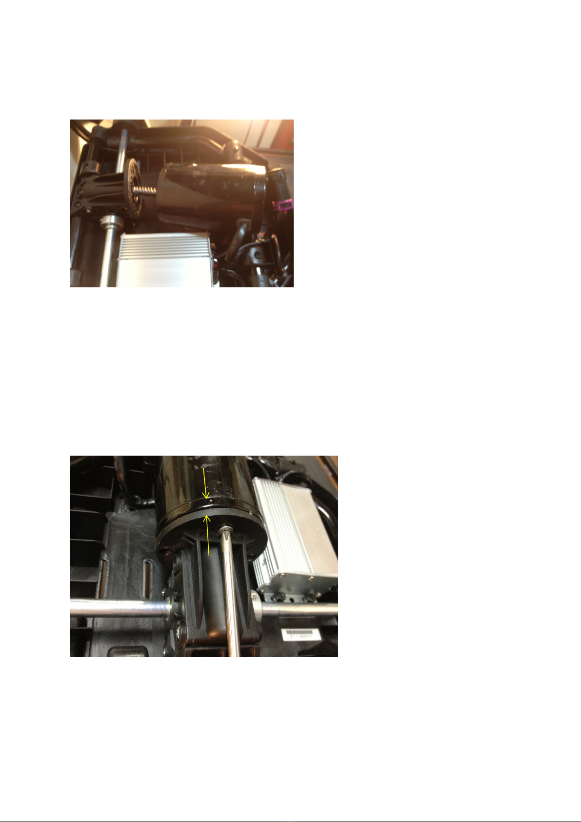
YoucannowbegintoinserttheMotorintothegearbox.Youmayneedtoturntheaxleslightly,to
allowthewormdrivegearstomatchcorrectlyandtheMotorbodytomatchupcorrectlywiththe
GearboxFlangeasperFigureNos28&29.
GTLITHIUMV1Workshopmanual 18
©2013ElkingtonGolfPtyLtd
FigureNo28
Fitthe3MotorretaingscrewsandensurethattheMotoriscorrectlyseatedagainsttheGearbox
flangebyholdinginwardpressureontheMotorandthentightenthe3screwsevenly.Referto
FigureNo29.
FigureNo29
ReconnecttheMotorwiringasperFigureNo24andrefitcableties,tosecurewiringtotheframe.

GTLITHIUMV1Workshopmanual 19
©2013ElkingtonGolfPtyLtd
7/REPLACINGTHEAXLEDRIVEPINS
Thisisaverysimpleprocessandallyouwillrequireisasmallhammeranda4mmpinpunch.Begin
byremovingthewheelbydepressingtheRedwheelreleasetabonthewheelasperfigureNo30.
ToremovetheoldDrivepinusea4mmpunchaspicturedinFigureNo31.ToinstallnewDrivepin,
useasmallhammerandgentlytapthepinintotheaxle,beingverycarefulnottobendtheaxle
duringthisprocessaspicturedonFigureNo32.Itisrecommendedthatyouusealittleloctiteon
theDrivePinwheninstalling.
FigureNo30
FigureNo31
FigureNo32

GTLITHIUMV1Workshopmanual 20
©2013ElkingtonGolfPtyLtd
8/REPLACINGTHESTEMCABLE
ToBeginthisprocess,firstlybeginbyremovingtheTopHandleassemblyasperFigureNos1to4.
OncetheTopHandlehasbeenremovedfromthebuggy,folddowntheframeandbegintopullout
theStemCableinthedirectionofthearrow,whichishousedwithinaflexibleprotectivetubeas
showninFigureNo33.
FigureNo33
Keeppullingoutwardontheflexibletubeinthedirectionofthearrow,untiltheStemCableis
releasedfromtheuppersectionoftheMainFrame,asperFigureNo34.
FigureNo34
OncetheStemcablehasbeenfullyreleasedfromtheUpperMainFrametube,slidetheflexible
protectivecoverfullyofftheStemCable,buttakespecialnotewhichwayyouhaveremovedthis
cover,asitwillneedtoberefittedthesamewayitwasoriginally,referFigureNo35.
Table of contents
Popular Offroad Vehicle manuals by other brands


Gravely
Gravely Atlas JSV 3000 EFI Owner's/operator's manual

Arctic Cat
Arctic Cat TRV 2015 Operator's manual

Arctic Cat
Arctic Cat 2010 700 Diesel SD Operator's manual

Yamaha
Yamaha Big Bear YFM400R owner's manual

Polaris
Polaris Trail Boss 330 Quadricycle Specification sheet

Polaris
Polaris 600 IQ Racer owner's manual

Polaris
Polaris Sportsman Touring 570 2022 owner's manual

Polaris
Polaris SNOWMOBILE 2001 Owner's safety and maintenance manual
Tracker Off-Road
Tracker Off-Road 800SX Service manual

Arctic Cat
Arctic Cat DVX 250 2007 Service manual

Polaris
Polaris RZR Trail S 2022 owner's manual

Ontario Drive & Gear
Ontario Drive & Gear Centaur V2001G Operator's manual